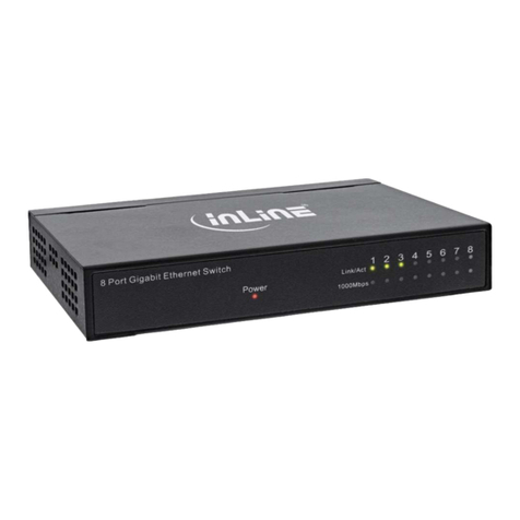
Inline 32305Q User manual

BEDIENUNGSANLEITUNG
USER MANUAL
ARTIKEL-NR. / ITEM NUMBER: 32305Q
POE+ GIGABIT NETZWERK SWITCH
5-PORT (4X POE+)
POE+ GIGABIT NETWORK SWITCH 5 PORT
(4X POE+)
USER MANUAL

www.inline-info.com
2
1. ALLGEMEINES
GÜLTIGKEIT:
Diese Bedienungsanleitung gilt für folgendes Produkt: 32305Q InLine®
PoE+ Gigabit Netzwerk Switch 5 Port (4x PoE+), 1GBit/s, Desktop, Metall,
lüfterlos
HERSTELLER:
INTOS ELECTRONIC AG
Siemensstraße 11
D-35394 Gießen
DATUM:
Mai 2021
2. LIEFERUMFANG
• 1x InLine® PoE+ Gigabit Netzwerk Switch
• 2x Bedienungsanleitung (deutsch/englisch)
• 1x Netzkabel
• 4x Gummifüße
Prüfen Sie den Lieferumfang auf Vollständigkeit. Sollten einzelne Bestandteile
fehlen, kontaktieren Sie bitte Ihren Fachhändler.
3. ERKLÄRUNG VON WARNSYMBOLEN UND
HINWEISEN
4. TECHNISCHE EIGENSCHAFTEN
• Standards: IEEE 802.3 10Base-T, IEEE 802.3u 100Base-TX, IEEE 802.3ab
1000Base-T, IEEE 802.3x Flusskontrolle, IEEE 802.3af Power over
Ethernet, IEEE 802.3at Power over Ethernet Plus
• Ports: 4x 10/100/1000Base-T RJ45, Auto-MDI/MDI-X, PoE+ Unterstützung
1x 10/100/1000Base-T RJ45, Auto-MDI/MDI-X
• PoE Art der Stromversorgung: Endspan
• PoE-Ausgangsspannung: Pro Port 48~56V DC
• PoE-Ausgangsleistung: Pro Port max. 30 Watt
• Anschlussbelegung Pins: 1/2(+), 3/6(-)
• Gesamtleistung: 60 Watt
• LED-Anzeigen: Power / Uplink / Link / PoE (1-4)
• Abmessungen (B x T x H): 160x122x43mm
• Gewicht: ca. 776 g
• Spannungsaufnahme: 100-240V AC, 50/60 Hz
• Umgebungsbedingungen: Betriebstemperatur 0-40°C, Lagertemperatur
-20-70°C, Luftfeuchtigkeit 20-95% nicht kondensierend
5. BESTIMMUNGSGEMÄSSE VERWENDUNG
Der InLine® Gigabit Netzwerk Switch 5 Port (4x PoE+) bietet eine schnelle
Netzwerkverbindung sowie PoE+-Unterstützung an 4 der 5 Ports. Die 5x
10/100/1000Mb/s Auto-Negotiation RJ45-Ports unterstützen alle Auto MDI/
MDIX. Der Switch ist eine einfach zu bedienende und leistungsstarke Lösung,
um Ihr altes Netzwerk zu einem Gigabit Netzwerk zu verbessern und um
PoE-fähige Geräte wie IP-Kameras, IP-Telefone, Access Points, etc. über das
angeschlossene Patchkabel mit Strom zu versorgen.
Allgemeine Warnhinweise:
• Setzen Sie den InLine® PoE+ Gigabit Netzwerk Switch im Betrieb keiner
großen Hitze aus
• Vor Staub und Feuchtigkeit schützen
6. NICHT BESTIMMUNGSGEMÄSSE VERWENDUNG
Als nicht bestimmungsgemäße Verwendung im Sinne einer vorhersehbaren
Fehlanwendung gilt:
• Bauen Sie den InLine® PoE+ Gigabit Netzwerk Switch nicht auseinander
7. ANWENDUNG / INBETRIEBNAHME
Hardware-Installation
1. Stecken Sie das mitgelieferte Netzkabel in die Eingangsbuchse auf der
Rückseite des Geräts und das andere Ende in eine Steckdose. Die LED
„PWR“ leuchtet.
2. Verbinden Sie ein RJ45-Kabel mit einem der Ethernet-Port des Switches.
3. Verbinden Sie die andere Seite des RJ45-Kabels mit einem nicht PoE-fä-
higen oder einem nach IEEE 802.3af/at PoE-fähigen Endgerät, um Daten
oder Daten + Strom über diesen Port bereitzustellen. Bei Stromübertra-
gung leuchtet zur Bestätigung die LED-Anzeige „PoE“.
4. Stellen Sie sicher, dass das verbundene Endgerät eingeschaltet ist.
Sollte es trotzdem nicht funktionieren, vergewissern Sie sich, dass alle
Ethernet-Kabel ordnungsgemäß angeschlossen wurden.
INHALT
1. Allgemeines.....................................................................................................................................................................................................................2
2. Lieferumfang...................................................................................................................................................................................................................2
3. Erklärung von Warnsymbolen und Hinweisen...............................................................................................................................................................2
4. Technische Eigenschaften .............................................................................................................................................................................................2
5. Bestimmungsgemässe Verwendung.............................................................................................................................................................................2
6. Nicht bestimmungsgemässe Verwendung....................................................................................................................................................................2
7. Anwendung / Inbetriebnahme....................................................................................................................................................................................2-3
8. Wartung und Reinigung..................................................................................................................................................................................................3
9. Zubehör...........................................................................................................................................................................................................................3
10. Entsorgung......................................................................................................................................................................................................................3
11. Disclaimer .......................................................................................................................................................................................................................3
HINWEIS!
Dieses Symbol kennzeichnet Informationen, die zum bes-
seren Verständnis beitragen.
Die Ports 1-4 auf der Geräterückseite unterstützen PoE,
der Port an der Vorderseite nicht. Wenn Sie ein Endgerät an
einen der PoE-Ports anschließen, das kein PoE unterstützt,
wird der Switch dieses Endgerät nicht mit Strom versorgen,
allerdings weiterhin mit Datenpaketen. Diese Funktion er-
laubt es Ihnen, bedenkenlos PoE-kompatible und nicht PoE-kompatible Ge-
räte in Ihrem Netzwerk zu mischen.
Platzierung des Switches
1. Befestigen Sie bei Bedarf die mitgelieferten Gummifüße an der Untersei-
te des Switches, um rutschfesten Halt zu erzielen.
2. Achten Sie darauf, dass um den Switch herum mindestens 30 cm Platz
sind, damit Wärme ordnungsgemäß abgeführt werden kann.
LED-Anzeigen
8. WARTUNG UND REINIGUNG
Reinigen Sie den Switch mit einem trockenen, weichen Tuch. Verwenden Sie
kein Wasser oder sonstige Reinigungsflüssigkeiten, die die Elektronik schä-
digen können.
9. ZUBEHÖR
769*** InLine® Patchkabel, S/FTP (PiMf), Cat.6, 250MHz, halogen-
frei, Kupfer, verschiedene Farben und Längen
764*** InLine® Patchkabel, S/FTP (PiMf), Cat.6, 250MHz, PVC,
Kupfer, verschiedene Farben und Längen
768*** InLine® Patchkabel, S/FTP (PiMf), Cat.6A, 500MHz, halo-
genfrei, Kupfer, verschiedene Farben und Längen
788*** InLine® Patchkabel, S/FTP (PiMf), Cat.8.1, 2000MHz,
halogenfrei, Kupfer, verschiedene Farben und Längen
10. ENTSORGUNG
Elektrische und elektronische Geräte sowie Batterien dürfen nicht mit dem
Hausmüll entsorgt werden. Der Verbraucher ist gesetzlich verpflichtet,
elektrische und elektronische Geräte sowie Batterien am Ende ihrer Lebens-
dauer an den dafür eingerichteten, öffentlichen Sammelstellen oder an die
Verkaufsstelle zurückzugeben.
11. DISCLAIMER
1. Ausgabe Deutsch 19/2021
Dokumentation © 2021 INTOS ELECTRONIC AG
Alle Rechte vorbehalten. Ohne schriftliche Zustimmung des Herausgebers
darf dieses Handbuch auch nicht auszugsweise in irgendeiner Form re-
produziert werden oder unter Verwendung elektronischer, mechanischer
oder chemischer Verfahren vervielfältigt oder verarbeitet werden. Es ist
möglich, dass das vorliegende Handbuch noch drucktechnische Mängel
oder Druckfehler aufweist. Die Angaben in diesem Handbuch werden je-
doch regelmäßig überprüft und Korrekturen in der nächsten Ausgabe
vorgenommen. Für Fehler technischer oder drucktechnischer Art und ihre
Folgen übernehmen wir keine Haftung. Alle Warenzeichen und Schutzrech-
te werden anerkannt. Änderungen im Sinne des technischen Fortschritts
können ohne Vorankündigung vorgenommen werden. Unsere Produkte,
einschließlich der Verpackung, sind kein Spielzeug, sie könnten kleine Teile
und scharfe Objekte enthalten. Bitte von Kindern fernhalten.
InLine ist eine Marke der:
INTOS ELECTRONIC AG
Siemensstrasse 11, D-35394 Giessen
www.intos.de
info@inline-info.com 3
Frontansicht
Rückansicht
LED-
Anzeige Farbe Status Funktion
Power Grün leuchtet Switch wird ordnungsgemäß mit Strom
versorgt
UPLINK Grün leuchtet Port ist mit 1000 Mb/s an Gerät ange-
schlossen
Gelb leuchtet Port ist mit 10/100 Mb/s an Gerät ange-
schlossen
Grün
oder
Gelb
blinkt Port ist aktiv für das Senden / Empfan-
gen von Daten
LINK Grün leuchtet Port ist mit 1000 Mb/s an Gerät ange-
schlossen
Gelb leuchtet Port ist mit 10/100 Mb/s an Gerät ange-
schlossen
Grün
oder
Gelb
blinkt Port ist aktiv für das Senden / Empfan-
gen von Daten
PoE Grün leuchtet PoE-Funktion ist aktiv
n/a aus PoE-Funktion ist deaktiviert - Funktion
eines reinen LAN-Ports
Anwendungsdiagramm
Keine Gegenstände auf dem Switch platzieren!

www.inline-info.com
4
1. GENERAL INFORMATION
VALIDITY:
This user manual applies to the following product: 32305Q InLine® PoE+
Gigabit Network Switch 5 Port (4x PoE+), 1Gbps, desktop, metal, without
fan
MANUFACTURER:
INTOS ELECTRONIC AG
Siemensstraße 11
D-35394 Gießen
DATE:
May 2021
2. CONTENT OF DELIVERY
• 1x InLine® PoE+ Gigabit Network Switch
• 2x User manual (German/English)
• 1x Power cord
• 4x Rubber feet
Please check the content of delivery for completeness. If individual compo-
nents are missing, please contact your dealer.
3. EXPLANATION OF WARNING SYMBOLS AND
NOTES
4. TECHNICAL CHARACTERISTICS
• Standards: IEEE 802.3 10Base-T, IEEE 802.3u 100Base-TX, IEEE 802.3ab
1000Base-T, IEEE 802.3x Flow Control, IEEE 802.3af Power over Ethernet,
IEEE 802.3at Power over Ethernet Plus
• Ports: 4x 10/100/1000Base-T RJ45, Auto-MDI/MDI-X, PoE+ support
1x 10/100/1000Base-T RJ45, Auto-MDI/MDI-X
• PoE type of power supply: End-span
• PoE output voltage: Per port 48~56V DC
• PoE output power: Per port max. 30 watts
• Power pin assignment: 1/2(+), 3/6(-)
• Total power: 60 watts
• LED indicators: POWER / UPLINK / LINK / PoE (1-4)
• Dimensions (W x D x H): 160x122x43mm
• Weight: appr. 776 g
• Power requirement: 100-240V AC, 50/60 Hz
• Operating environment: Operating temperature 0-40°C, storage tempera-
ture -20-70°C, humidity 20-95% non-condensing
5. INTENDED USE
The InLine® Gigabit Network Switch 5 Port (4x PoE+) offers a fast net-
work connection as well as PoE+ support on 4 of the 5 ports. The 5x
10/100/1000Mb/s auto-negotiation RJ45 ports all support Auto MDI/MDIX.
The switch is an easy-to-use and powerful solution to upgrade your old net-
work to a Gigabit network and to power PoE-enabled devices such as IP ca-
meras, IP phones, access points, etc. via the attached patch cable.
General warnings:
• Do not expose the InLine® PoE+ Gigabit Network Switch to extreme
heat
• Protect from dust and moisture
6. IMPROPER USE
The following shall be deemed to be improper use within the meaning of a
foreseeable misuse:
• Do not disassemble the InLine® PoE+ Gigabit Network Switch
7. APPLICATION / COMMISSIONING
Hardware installation
1. Plug the supplied power cord into the input jack on the back of the unit
and the other end into a power outlet. The „PWR“ LED lights up.
2. Connect an RJ45 cable to one of the Ethernet ports of the switch.
3. Connect the other side of the RJ45 cable to a non-PoE capable or IEEE
802.3af/at PoE capable end device to provide data or data + power
through this port. When power is transmitted, the „PoE“ LED indicator
lights up to confirm.
4. Make sure the connected device is turned on. If it still does not work,
make sure all Ethernet cables are properly connected.
CONTENT
1. General information........................................................................................................................................................................................................4
2. Content of delivery .........................................................................................................................................................................................................4
3. Explanation of warning symbols and notes...................................................................................................................................................................4
4. Technical characteristics................................................................................................................................................................................................4
5. Intended use ...................................................................................................................................................................................................................4
6. Improper use...................................................................................................................................................................................................................4
7. Application / commissioning......................................................................................................................................................................................4-5
8. Maintenance and cleaning .............................................................................................................................................................................................5
9. Accessories ....................................................................................................................................................................................................................5
10. Disposal ..........................................................................................................................................................................................................................5
11. Disclaimer .......................................................................................................................................................................................................................5
NOTE!
This symbol indicates information that contributes to a bet-
ter understanding.
Ports 1-4 on the back of the device support PoE, but the
port on the front does not. If you connect a terminal device
to one of the PoE ports that does not support PoE, the switch
will not provide power to that terminal device, but will cont-
inue to provide data packets. This feature allows you to mix
PoE-compatible and non-PoE-compatible devices on your network without
worry.

Placement of the switch
1. If necessary, attach the supplied rubber feet to the bottom of the switch
for a non-slip grip.
2. Make sure that there is at least 30 cm of space around the switch so that
heat can be properly dissipated.
LED indication
8. MAINTENANCE AND CLEANING
Clean the switch with a dry, velvety cloth. Do not use water or other cleaning
fluids that may damage the electronics.
9. ACCESSORIES
769*** InLine® Patch Cable S/FTP PiMF Cat.6 250MHz copper
halogen free, various colors and lengths
764*** InLine® Patch Cable S/FTP PiMF Cat.6 250MHz PVC
copper grey 10m, various colors and lengths
768*** InLine® Patch Cable S/FTP PiMF Cat.6A halogen free
500MHz, various colors and lengths
788*** InLine® Patch Cable S/FTP PiMF Cat.8.1 halogen free
2000MHz, various colors and lengths
10. DISPOSAL
Electrical and electronic equipment and batteries must not be disposed of
with household waste. The consumer is obliged by law to return electrical
and electronic equipment and batteries at the end of their service life to the
designated public collection points or to the point of sale.
11. DISCLAIMER
1. Edition English 19/2021
Documentation © 2021 INTOS ELECTRONIC AG
All rights reserved. No part of this manual may be reproduced in any form
or duplicated or processed using electronic, mechanical or chemical pro-
cesses without the publisher´s written consent. It is possible that this ma-
nual may still contain typographical defects or printing errors. However,
the information in this manual is reviewed regularly and corrections will be
made in the next edition. We accept no liability for technical or typographi-
cal errors and their consequences. All trademarks and industrial property
rights are acknowledged. Changes in the sense of technical progress can
be made without prior notice. Our products, including packaging, are not
toys; they may contain small parts and sharp objects. Keep away from chil-
dren, please.
InLine is a brand of:
INTOS ELECTRONIC AG
Siemensstrasse 11, D-35394 Giessen
www.inline-info.com
info@inline-info.com 5
Front view
Rear view
LED
Indicator Color Status Function
Power Green ON Switch is on and correctly powered
UPLINK Green ON Port is connected to device at 1000Mbps
Yellow ON Port is connected to device at 10/100Mbps
Green
or
Yellow
Flashing Port is active for data sending/reveiving
LINK Green ON Port is connected to device at 1000Mbps
Yellow ON Port is connected to device at 10/100Mbps
Green
or
Yellow
Flashing Port is active for data sending/reveiving
PoE Green ON PoE function is enabled
n/a OFF PoE function is disabled
It acts as a regular LAN port
Application diagram
Do not place any objects on the switch!

www.inline-info.com
FRAGEN ZU PRODUKTEN ODER ZUR TECHNIK
ANY QUESTIONS?
Wir helfen das passende Produkt für Ihren Bedarf zu fin-
den, sind bei der Bezugsquellensuche behilflich, beant-
worten technische Fragen und unterstützen Sie bei der Installati-
on Ihrer InLine Produkte, z. B. mit den aktuellsten Treibern.
MO. - FR.: 09:00 - 17:00 UHR
DE
live.inline-info.com
We will help you to find suitable products for
your needs, we provide support in finding
supply sources, answer technical questions and glad-
ly help you to install your InLine products e.g. by provi-
ding up-to-date drivers.
MO. - FR.: 9AM TO 5PM
EN
Table of contents
Languages:
Other Inline Switch manuals

Inline
Inline 33051H User manual

Inline
Inline 32316P User manual

Inline
Inline 32308M User manual

Inline
Inline 33293H User manual

Inline
Inline 62652I User manual

Inline
Inline 33271O User manual

Inline
Inline SWP123 User manual

Inline
Inline 63652I User manual

Inline
Inline IN3564HR User manual

Inline
Inline IN3554 User manual

Inline
Inline IN3546R User manual

Inline
Inline IN3606 User manual

Inline
Inline IN3526vi User manual

Inline
Inline 60603I User manual

Inline
Inline A3H User manual

Inline
Inline 33271N User manual

Inline
Inline 62642I User manual

Inline
Inline 62602I User manual

Inline
Inline IN3526 User manual

Inline
Inline IN3552R User manual