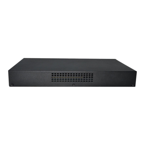
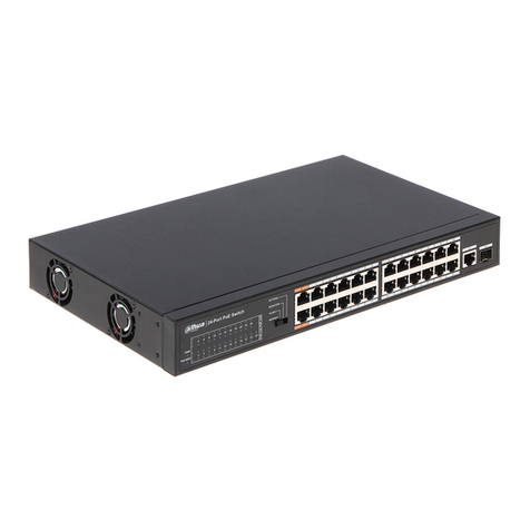
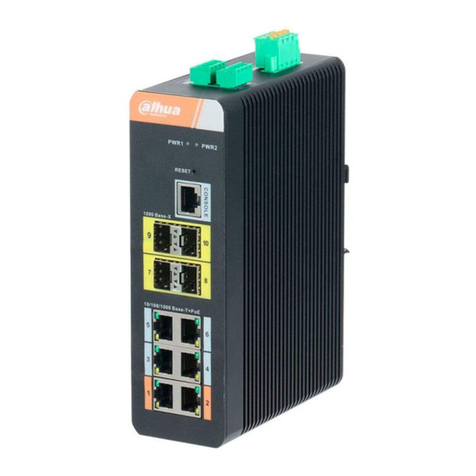
Dahua Technology DH-PFS5936-24GF8GT4XF User manual

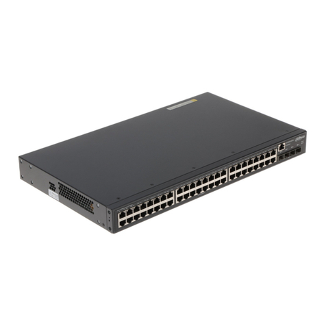
Dahua 36-Port Managed Gigabit L3 Switch
Quick Start Guide
V1.0.0
ZHEJIANG DAHUA VISION TECHNOLOGY CO., LTD.

Foreword I
Foreword
General
This manual introduces the functions and operations of 36-port managed Gigabit L3 switch
(hereinafter referred to as "the Device").
Model
DH-PFS5936-24GF8GT4XF
Safety Instructions
The following categorized signal words with defined meaning might appear in the Guide.
Signal Words
Meaning
DANGER
Indicates a high potential hazard which, if not avoided, will result
in death or serious injury.
WARNING
Indicates a medium or low potential hazard which, if not avoided,
could result in slight or moderate injury.
CAUTION
Indicates a potential risk which, if not avoided, could result in
property damage, data loss, lower performance, or unpredictable
result.
TIPS
Indicates dangerous high voltage.
Take care to avoid coming into contact with electricity.
NOTE
Indicates a laser radiation hazard.
Take care to avoid exposure to a laser beam.
Revision History
Version
Revision Content
Release Time
V1.0.0
First release.
June 2019
Privacy Protection Notice
As the device user or data controller, you might collect personal data of others such as face,
fingerprints, car plate number, Email address, phone number, GPS and so on. You need to be
in compliance with the local privacy protection laws and regulations to protect the legitimate
rights and interests of other people by implementing measures include but not limited to:
providing clear and visible identification to inform data subject the existence of surveillance
area and providing related contact.

Foreword II
About the Manual
The manual is for reference only. If there is inconsistency between the manual and the
actual product, the actual product shall prevail.
We are not liable for any loss caused by the operations that do not comply with the manual.
The manual would be updated according to the latest laws and regulations of related
regions. For detailed information, see the paper manual, CD-ROM, QR code or our official
website. If there is inconsistency between paper manual and the electronic version, the
electronic version shall prevail.
All the designs and software are subject to change without prior written notice. The product
updates might cause some differences between the actual product and the manual. Please
contact the customer service for the latest program and supplementary documentation.
There still might be deviation in technical data, functions and operations description, or
errors in print. If there is any doubt or dispute, please refer to our final explanation.
Upgrade the reader software or try other mainstream reader software if the manual (in PDF
format) cannot be opened.
All trademarks, registered trademarks and the company names in the manual are the
properties of their respective owners.
Please visit our website, contact the supplier or customer service if there is any problem
occurred when using the device.
If there is any uncertainty or controversy, please refer to our final explanation.

Table of Contents III
Table of Contents
Foreword.................................................................................................................................................... I
1 Overview................................................................................................................................................. 1
Product Introduction...................................................................................................................... 11.1 Front Panel.................................................................................................................................... 11.2 Rear Panel.................................................................................................................................... 11.3 Indicator Description..................................................................................................................... 21.4
2 Installing the Device.............................................................................................................................. 3
Installing the Switch...................................................................................................................... 32.1 2.1.1 Installing the Switch on the 19-inch Standard Rack........................................................... 3
2.1.2 Installing the Switch on the Working Desk......................................................................... 4
Connecting the Cables.................................................................................................................. 42.2 2.2.1 Connecting the Configuration Cable .................................................................................. 4
2.2.2 Connecting the GND Cable................................................................................................ 5
2.2.3 Connecting the Power Cable.............................................................................................. 5
2.2.4 Installing SFP Module and Connecting the Optical Fiber .................................................. 6
3 Logging in the Device........................................................................................................................... 7
VLAN Configuration...................................................................................................................... 73.1 Cybersecurity Recommendations ..................................................................................... 9Appendix 1

Overview 1
1 Overview
Product Introduction1.1
The 36-Port Managed Gigabit L3 Switch has the following model:
Table 1-1 Model
Name
Model
36-Port Managed Gigabit L3
Switch with 24×100/1000Mbps
SFP Ports, 8×Gigabit Ports and
4×1G/10G SFP+
DH-PFS5936-24GF8GT4XF
Front Panel1.2
See Figure 1-1 for the front panel of the switch.
Front panelFigure 1-1
Table 1-2 Front panel description
No.
Description
1
100/1000 M Base-X SFP
2
10/100/1000 M Base-T RJ–45 port
3
1/10 G Base-X SFP+
4
Console port
5
SYS
6
PWR (power indicator)
7
RESET
8
ALR
Rear Panel1.3
See Figure 1-2 for the rear panel of the switch.

Overview 2
Rear panelFigure 1-2
Table 1-3 Rear panel description
No.
Description
1
GND screw
2
AC power port
Indicator Description1.4
Table 1-4 Indicator description
Indicator
Status
Description
PWR
ON (green light)
The switch is powered on and the power
module is working properly.
OFF
The switch is not powered on or the
power module is not working properly.
SYS
Flashing (green light)
The system is working properly.
OFF
The system is not working properly.
ALR
ON (red light)
There is abnormal alarm.
OFF
There is no abnormal alarm.
RJ-45 port
Link/Act
ON (green light)
The RJ-45 port is working at the rate of
10/100/1000 Mbps and the port is
connected to the opposite device
properly.
Flashing (yellow light)
The RJ-45 port is working at the rate of
10/100/1000 Mbps and the port is
sending and receiving data.
OFF
The RJ-45 port is not connected to the
opposite device or connection failed.
SFP port
module
ON (green light)
The SFP port is working at the rate of
1/10 Gbps and the port is connected to
the opposite device properly.
Flashing (green light)
The SFP port is working at the rate of
1/10 Gbps and the port is sending and
receiving data.
OFF
The SFP port is not connected to the
opposite device or connection failed.

Installing the Device 3
2 Installing the Device
The switch can be installed on the 19-inch standard rack, and it can also be directly placed on
the working desk.
To avoid damage to the device or human, follow the attentions:
Do not place the switch near water and keep away from humid environment to avoid water
and moisture getting into the device.
Make sure the working environment of switch is clean, because the dust might cause
electrostatic adsorption, which not only affects the switch working life, but also causes
communication failure easily.
Make sure the air vent is not blocked, and do not pile up the switch.
Make sure the switch is working at the proper and stable voltage.
Make sure the grounding is normal with the grounding terminal at the rear panel of the
switch before using the switch.
Unplug the power before cleaning the switch. Do not wipe the switch with wet cloth, and do
not clean the switch with liquid.
Do not disassemble the switch enclosure when the switch is working, and do not optionally
disassemble the switch enclosure even if the switch is not powered on.
The switch is the class A product, and it might cause radio disturbance in the environment. You
could take practical measures to avoid radio disturbance.
Installing the Switch2.1
2.1.1 Installing the Switch on the 19-inch Standard Rack
To install the switch on the 19-inch standard rack, do the following:
Check the grounding of the rack, and make sure the rack is stable.Step 1 Fix the rackmount hangers on both sides of the switch front panel with the screws.Step 2 Tightening the rackmount hangersFigure 2-1
Place the switch on the carrier on the rack, and push the switch along the guide slot toStep 3 a proper position.
Fix the rackmount hangers on the guide slot of the rack with the screws to make sureStep 4 the switch is secured.
Installing the Device 4
Installing the switchFigure 2-2
The rackmount hangers are not for sustaining the weight of the switch, and they
are for fixing the switch. The carrier is necessary for sustaining the switch.
2.1.2 Installing the Switch on the Working Desk
You can place the switch on the clean, stable, and grounded working desk.
To install the switch on the working desk, do the following:
Place the switch upside down carefully, and clean the groove on the switch baseboardStep 1 with the soft cloth. Make sure there is no oil or dust.
Tear off the sticker on the surface of the supplied foot pad, and paste the foot pad on
Step 2 the groove on the switch baseboard.
Turn the switch over, and place the switch on the working desk right side up.Step 3
Connecting the Cables2.2
2.2.1 Connecting the Configuration Cable
Connecting the configuration cableFigure 2-3

Installing the Device 5
To connect the configuration cable, do the following:
Connect the DB-9 plug of the configuration cable to the serial port of the PC.Step 1 Connect the RJ-45 port of the configuration cable to the Console port of the switch.
Step 2
2.2.2 Connecting the GND Cable
The GND cable is not supplied, and you need to purchase it by yourself.
Connecting the GND cable well is the important safeguard for lightning protection and
anti-electromagnetic interference.
To connect the GND cable, do the following:
Remove the GND screw on the switch GND point with the cross screwdriver, andStep 1 thread the GND screw through the hole on the OT terminal of the GND cable. Rotate
the GND screw clockwise with the cross screwdriver, and fix the OT terminal of the
GND cable with the switch GND point.
Wind the other side of the GND cable into the circle with the nipper pliers.Step 2 Connect the other side of the GND cable with the grounding bar, and rotate the hex nutStep 3 clockwise with the wrench to fix the other side of the GND cable on the grounding pole.
Connecting the GND cableFigure 2-4
2.2.3 Connecting the Power Cable
Make sure the switch is well grounded before you connect the power cable.
To connect the power cable, do the following:
Insert one side of the supplied power cable into theAC power supply hub of the switch.Step 1 Connect the other side of the power cable to the externalAC power socket.Step 2 Connecting the power cable
Figure 2-5
12 3

Installing the Device 6
2.2.4 Installing SFP Module and Connecting the Optical Fiber
WARNING
Do not touch the golden finger of the SFP module when installing the SFP module.
Do not pull out the dustproof plug of the SFP module before connecting the optical fiber.
Do not directly insert the SFP module connected with the optical fiber into the SFP slot.
Pull out the optical fiber first before inserting the SFP module.
To install the SFP module and connect the optical fiber, do the following:
Wear the antistatic wrist, and make sure the antistatic wrist and your skin are in goodStep 1 contact and well grouned.
Lift the handle of SFP module upward vertically. Hold the SFP module by both sides,Step 2 and push it gently into the SFP slot till the SFP module is firmly connected to the slot
Installing the SFP moduleFigure 2-6
Remove the dust cap on the LC connector of the optical fiber and the dustproof plug ofStep 3 the SFP module.
Connect the LC connector of the optical fiber with the SFP module.Step 4 Connecting the optical fiberFigure 2-7

Logging in the Device 7
3 Logging in the Device
The default IP address of the switch is 192.168.1.110. You can only log in the device by
Console port for first time login. The user name and the password are both “admin”, and the
baud rate of the serial port is 115200. You can view the actual IP address through show ip
interface command line.
Login by console port is the most basic way to log in the local interface, and it is also the
method to configure other ways to log in the device. You can see the command line manual for
details.
VLAN Configuration
3.1
Virtual Local Area Network (VLAN) is frequently and widely applied. It is the basic to divide the
network. VLAN is the network that multiple devices are logically organized as one network,
regardless of the physical location of the devices. Every VLAN is a logical network with all
functions and attributes of traditional physical network. Every VLAN is a broadcast domain, and
the broadcast packet can only be forwarded within one VLAN. The broadcast packet cannot be
forwarded across different VLANs.
Port-based VLAN
Port-based VLAN is that one switch can divide the logical working groups by controlling
interoperability between two and several ports. Dividing the port VLAN reasonably can enhance
network security, improve bandwidth availability, and reduce the probability of broadcast storm.
This series of products support 4094 VLANs. When you create the VLAN, you need to select a
VLAN ID which ranges from 2 through 4094. By default, VLAN 1 is cerated, and it cannot be
deleted.
Application Example
Networking Requirement
There are two users, user 1 and user 2. They need to be in different VLANs because the
network function and environment they use are different. User 1 belongs to VLAN 2,
connected to the switch port G1/1 (GigabitEthernet 1/1). User 2 belongs to VLAN 3, connected
to switch port G1/2 (GigabitEthernet 1/2).

Logging in the Device 8
VLAN networkingFigure 3-1
Configuration Procedure
To configure the switch, do the following:
Create the VLAN.Step 1
SWITCH #configure terminal
SWITCH (config)#vlan 2
SWITCH (config-vlan)# exit
SWITCH (config)#vlan 3
SWITCH (config-vlan)# exit
Allocate the ports into the VLAN.Step 2
SWITCH(config)# interface GigabitEthernet 1/1
SWITCH (config-if)# switchport access vlan 2
SWITCH (config-if)# exit
SWITCH (config)# interface GigabitEthernet 1/2
SWITCH (config-if)# switchport access vlan 3
SWITCH (config-if)# exit
Configure the VLAN IP address.Step 3
SWITCH #configure terminal
SWITCH (config)# interface vlan 2
SWITCH (config-if-vlan)# ip address 192.168.2.1 255.255.255.0
SWITCH (config-if-vlan)#exit
SWITCH (config)#interface vlan 3
SWITCH (config-if-vlan)# ip address 192.168.3.1 255.255.255.0
SWITCH (config-if-vlan)#exit

Cybersecurity Recommendations 9
Cybersecurity RecommendationsAppendix 1
Cybersecurity is more than just a buzzword: it’s something that pertains to every device that is
connected to the internet. IP video surveillance is not immune to cyber risks, but taking basic
steps toward protecting and strengthening networks and networked appliances will make them
less susceptible to attacks. Below are some tips and recommendations on how to create a
more secured security system.
Mandatory actions to be taken for basic equipment network security:
1. Use Strong Passwords
Please refer to the following suggestions to set passwords:
The length should not be less than 8 characters;
Include at least two types of characters; character types include upper and lower case
letters, numbers and symbols;
Do not contain the account name or the account name in reverse order;
Do not use continuous characters, such as 123, abc, etc.;
Do not use overlapped characters, such as 111, aaa, etc.;
2. Update Firmware and Client Software in Time
According to the standard procedure in Tech-industry, we recommend to keep your
equipment (such as NVR, DVR, IP camera, etc.) firmware up-to-date to ensure the
system is equipped with the latest security patches and fixes. When the equipment is
connected to the public network, it is recommended to enable the “auto-check for
updates” function to obtain timely information of firmware updates released by the
manufacturer.
We suggest that you download and use the latest version of client software.
“Nice to have” recommendations to improve your equipment network security:
1. Physical Protection
We suggest that you perform physical protection to equipment, especially storage devices.
For example, place the equipment in a special computer room and cabinet, and implement
well-done access control permission and key management to prevent unauthorized
personnel from carrying out physical contacts such as damaging hardware, unauthorized
connection of removable equipment (such as USB flash disk, serial port), etc.
2. Change Passwords Regularly
We suggest that you change passwords regularly to reduce the risk of being guessed or
cracked.
3. Set and Update Passwords Reset Information Timely
The equipment supports password reset function. Please set up related information for
password reset in time, including the end user’s mailbox and password protection
questions. If the information changes, please modify it in time. When setting password
protection questions, it is suggested not to use those that can be easily guessed.
4. Enable Account Lock
The account lock feature is enabled by default, and we recommend you to keep it on to
guarantee the account security. If an attacker attempts to log in with the wrong password
several times, the corresponding account and the source IP address will be locked.

Cybersecurity Recommendations 10
5. Change Default HTTP and Other Service Ports
We suggest you to change default HTTP and other service ports into any set of numbers
between 1024~65535, reducing the risk of outsiders being able to guess which ports you
are using.
6. Enable HTTPS
We suggest you to enable HTTPS, so that you visit Web service through a secure
communication channel.
7. Enable Whitelist
We suggest you to enable whitelist function to prevent everyone, except those with
specified IP addresses, from accessing the system. Therefore, please be sure to add your
computer’s IP address and the accompanying equipment’s IP address to the whitelist.
8. MAC Address Binding
We recommend you to bind the IP and MAC address of the gateway to the equipment,
thus reducing the risk ofARP spoofing.
9. Assign Accounts and Privileges Reasonably
According to business and management requirements, reasonably add users and assign a
minimum set of permissions to them.
10. Disable Unnecessary Services and Choose Secure Modes
If not needed, it is recommended to turn off some services such as SNMP, SMTP, UPnP,
etc., to reduce risks.
If necessary, it is highly recommended that you use safe modes, including but not limited to
the following services:
SNMP: Choose SNMP v3, and set up strong encryption passwords and authentication
passwords.
SMTP: Choose TLS to access mailbox server.
FTP: Choose SFTP, and set up strong passwords.
AP hotspot: Choose WPA2-PSK encryption mode, and set up strong passwords.
11. Audio and Video Encrypted Transmission
If your audio and video data contents are very important or sensitive, we recommend that
you use encrypted transmission function, to reduce the risk of audio and video data being
stolen during transmission.
Reminder: encrypted transmission will cause some loss in transmission efficiency.
12. Secure Auditing
Check online users: we suggest that you check online users regularly to see if the
device is logged in without authorization.
Check equipment log: By viewing the logs, you can know the IP addresses that were
used to log in to your devices and their key operations.
13. Network Log
Due to the limited storage capacity of the equipment, the stored log is limited. If you need
to save the log for a long time, it is recommended that you enable the network log function
to ensure that the critical logs are synchronized to the network log server for tracing.
14. Construct a Safe Network Environment
In order to better ensure the safety of equipment and reduce potential cyber risks, we
recommend:
Disable the port mapping function of the router to avoid direct access to the intranet
devices from external network.

Cybersecurity Recommendations 11
The network should be partitioned and isolated according to the actual network needs.
If there are no communication requirements between two sub networks, it is
suggested to use VLAN, network GAP and other technologies to partition the network,
so as to achieve the network isolation effect.
Establish the 802.1x access authentication system to reduce the risk of unauthorized
access to private networks.

ZHEJIANG DAHUA VISION TECHNOLOGY CO., LTD.
Address: No.1199, Bin'an Road, Binjiang District, Hangzhou, P.R. China
Postcode: 310053
Tel: +86-571-87688883
Fax: +86-571-87688815
Email: overseas@dahuatech.com
Website: www.dahuasecurity.com
Table of contents
Other Dahua Technology Switch manuals

Dahua Technology
Dahua Technology DH-PFL2210-8ET-120 User manual

Dahua Technology
Dahua Technology DH-PFS4428-24GT-370 User manual

Dahua Technology
Dahua Technology DH-PFS5452-48GT4XF-400 User manual

Dahua Technology
Dahua Technology DH-PFS3006-4ET-36 User manual

Dahua Technology
Dahua Technology DH-PFS3005-4ET-36 User manual

Dahua Technology
Dahua Technology DH-PFS4210-8GT-150 User manual

Dahua Technology
Dahua Technology DH-PFS3103-1GT1ET-60 User manual

Dahua Technology
Dahua Technology DH-PFS4210-8GT-150 User manual

Dahua Technology
Dahua Technology DH-PFS4210-8GT-DP User manual

Dahua Technology
Dahua Technology DH-PFS3125-24ET-190 User manual