SPECS Nanonis SC5 User manual

Signal Conversion
SC5
User Manual
November 2016 (R6860)


SC5 Signal Conversion Index
•
iii
Contents
Conventions 6
Safety information 7
About this Manual 9
Introduction 10
Instrument Overview 11
Block diagram.................................................................................................................... 11
Front panel ......................................................................................................................... 12
Rear panel .......................................................................................................................... 13
Installation Guide 14
Content of delivery ............................................................................................................ 14
Setup .................................................................................................................................. 15
Connection to RC5............................................................................................................. 15
Electrical ground................................................................................................................ 17
Powering ............................................................................................................................ 18
Analog Inputs 19
Analog inputs connection................................................................................................... 19
Analog inputs schematic .................................................................................................... 23
Inputs calibration procedure............................................................................................... 23
Specifications (inputs) ....................................................................................................... 24
Analog Outputs 25
Analog outputs connection................................................................................................. 25
Analog outputs schematic .................................................................................................. 28
Bipolar and unipolar operation .......................................................................................... 28
hrDAC™............................................................................................................................ 31
Introduction ......................................................................................................... 31
Calibration procedure .......................................................................................... 32
Specifications (outputs) ..................................................................................................... 33
Fast Analog Output 34
Fast analog output connection............................................................................................ 34
Fast analog output schematic ............................................................................................. 34
Specifications (fast output) ................................................................................................ 35
Auxiliary Power Supply 36
Connection ......................................................................................................................... 36
Connection using Y-splitter ............................................................................................... 37
Schematic and connector pin layout .................................................................................. 37
Specifications (auxiliary power supply)............................................................................. 38
Troubleshooting 39
Instrument doesn’t power up correctly .............................................................................. 39
Auxiliary power supply doesn’t work correctly................................................................. 39

Specifications 40
General............................................................................................................................... 40
Analog inputs specifications .............................................................................................. 40
Analog outputs specifications ............................................................................................ 41
Fast analog output specifications ....................................................................................... 42
Auxiliary power supply specifications............................................................................... 42
Operating conditions .......................................................................................................... 43
Storage and transportation conditions................................................................................ 43
Performance Measurements 44
Analog inputs noise performance measurements............................................................... 44
Spectral noise....................................................................................................... 44
Noise and oversampling ...................................................................................... 45
Analog inputs DC performance measurements.................................................................. 47
DNL and INL....................................................................................................... 47
Offset and gain error............................................................................................ 48
Accuracy.............................................................................................................. 49
Input stability and temperature dependence ........................................................ 49
Temperature coefficient....................................................................................... 50
Analog inputs AC performance measurements.................................................................. 51
Frequency response ............................................................................................. 51
Linearity .............................................................................................................. 51
Harmonic distortion ............................................................................................. 52
Crosstalk .............................................................................................................. 53
Analog outputs noise performance measurements............................................................. 54
Spectral noise....................................................................................................... 54
Noise 0.1 Hz – 10 Hz........................................................................................... 55
Noise 10 Hz – 300 kHz........................................................................................ 56
Analog outputs DC performance measurements................................................................ 58
DNL and INL....................................................................................................... 58
Offset and gain error............................................................................................ 59
Accuracy.............................................................................................................. 60
Resolution............................................................................................................ 60
Output stability and temperature dependence...................................................... 61
Analog outputs AC performance measurements................................................................ 63
Frequency response ............................................................................................. 63
Output to input transfer function ......................................................................... 63
Linearity .............................................................................................................. 64
Lock-in linearity .................................................................................................. 65
Harmonic distortion ............................................................................................. 65
Crosstalk .............................................................................................................. 67
Fast analog output performance measurements ................................................................. 68
Spectral noise....................................................................................................... 68
Noise 0.1 Hz – 10 Hz........................................................................................... 69
Noise 10 Hz – 300 kHz........................................................................................ 69
Offset and gain error............................................................................................ 70
Frequency response ............................................................................................. 71
Legal Information 73
Warranty ............................................................................................................................ 73
Copyright ........................................................................................................................... 73
Trademarks ........................................................................................................................ 73
Declaration of Conformity ................................................................................................. 75
Index 77

SC5 Signal Conversion Conventions
•
5

SC5 Signal Conversion Conventions
•
6
Conventions
The following signal words and symbols appear in this manual:
Danger:Indicates a hazardous situation which, if not avoided, will result
in death or major
injury.
Warning: Indicates a hazardous situation which, if not avoided, could result in death or major
injury.
Caution:Indicates a hazardous situation which, if not avoided, could result in minor or moderate
injury.
High voltage: Risk of electric shock. Lethal voltages present.
Hot surface: Indicates that the surface of the instrument might become hot. Avoid coming into
contact with the hot surface.
Static sensitive devices: Observe precautions for handling electrostatic sensitive devices.
Note: Indicates a situation which, if not avoided, could result in damage or a malfunction of the
instrument.
Refer to instruction manual: The instruction manual mentioned in the text must be read before
operating the instrument.
Disconnect mains plug from electrical outlet: The mains plug must be disconnected from the
electrical outlet before proceeding.
Italic Commands, programs, menu items, functions, field names and product names are shown in italic
characters.
SC5 Signal Conversion Safety information
•
7
Safety information
•Carefully read this manual and all related documents before installing and using the instrument.
•The safety notes and warnings have to be obeyed at all times.
•The SC5 may only be installed and used by authorized and instructed personnel who have read this manual.
•The SC5 is designed for indoors dry laboratory use only.
•The SC5 may only be used as specified in this manual, otherwise it may not fulfill safety requirements.
•Do not install substitute parts or perform modifications to this instrument. No user serviceable parts inside.
•Do not operate the SC5 if it is damaged or not functioning properly. Never use damaged accessories.
•Do not operate the instrument during electrical storms, in order to avoid damaging the instrument.
•Never use corrosive or abrasive cleaning agents or polishes. If necessary, clean the instrument with a soft and
dry cloth, and make sure that it is completely dry and free from contaminants before returning it to service.
Warning: Lethal voltages are present inside the instrument. Disconnect the mains plug from the
electrical outlet before opening the instrument


SC5 Signal Conversion About this Manual
•
9
About this Manual
This manual is intended as a reference tool for users of the Nanonis SC5 signal conversion interface. It covers the
functionality of the instrument and explains its installation and operation.
This manual is not a service manual for the SC5.
Revision history
November 2016 (R6860) Updated release of the SC5 manual:
-Updated conformity declaration
August 2016 (R6641) Updated release of the SC5 manual
-Added smaller corrections
May 2013 (R3800) Initial release of the SC5 manual
The SPECS order number for this manual is: 2078000362

SC5 Signal Conversion Introduction
•
10
Introduction
The Nanonis Signal Conversion interface (SC5) is a high-performance analog frontend designed for applications
requiring high resolution, high precision, low noise, low drift, the highest DC and AC performance, and multiple-
channel functionality within a single enclosure. With up to 22-bit resolution, 1-ppm precision, and an output
bandwidth of 40 kHz, the SC5 is the ideal frontend for scanning probe microscopy (SPM), transport, and device
characterization experiments.
The SC5 features eight differential analog inputs with ±10 V input range and 100 kHz bandwidth with custom
designed low noise and low drift input stages. Each input signal is converted into the digital domain by a state-of-
the-art 18-bit, 1 MS/s ADC offering high resolution and oversampling reserves for additional resolution
enhancement.
The SC5 features eight single-ended outputs with ±10 V signal range and 40 kHz bandwidth, and an additional
output with 1 MHz bandwidth on the rear panel. Digital to analog conversion is achieved by using high-performance
20-bit, 1 MS/s R2R DACs, allowing for 1 ppm precision and ultra-low noise. The resolution can be enhanced further
to 22-bit using the patented hrDAC™ technology. All outputs are short-circuit proof, and clamped to GND when the
instrument is switched off.
For optimal temperature stability, the SC5 uses a custom temperature-stabilized, and thermally and mechanically
isolated precision voltage reference. Each function group has its own low-noise voltage regulators, and crosstalk is
minimized further by separately shielding the inputs, outputs, voltage reference, and digital processing circuits from
each other and from the power supply.
The instrument is powered by an internal linear power supply with automatic line voltage detection and
overtemperature protection. No switching power supplies or DC-DC converters are used. A separate winding of the
power transformer is used for the auxiliary ±15 V power supply, which can feed external instruments (e.g.
preamplifiers) with a current load of up to 300 mA.
The SC5 allows for a flexible electrical ground concept, which minimizes sources of noise and hum without
sacrificing safety of operation. The user can choose whether the reference ground of the analog electronics should be
connected to the experiment or to protection earth (PE). Protection earth is provided over the supply voltage
connector and is connected to the metallic enclosure of the SC5.
Computer control of the SC5 is achieved using the Nanonis RC5 real-time controller, to which the SC5 is connected
with a dedicated digital cable. Up to three SC5s can be connected to one RC5, therefore allowing data acquisition
systems with 24 input and 27 output channels. The SC5 should be connected only to the Nanonis RC5, and
throughout this manual it will be assumed that this is the case. For more details about the Nanonis RC5, please refer
to the RC5 User Manual.
SC5 Signal Conversion Instrument Overview
•
11
Instrument Overview
Block diagram
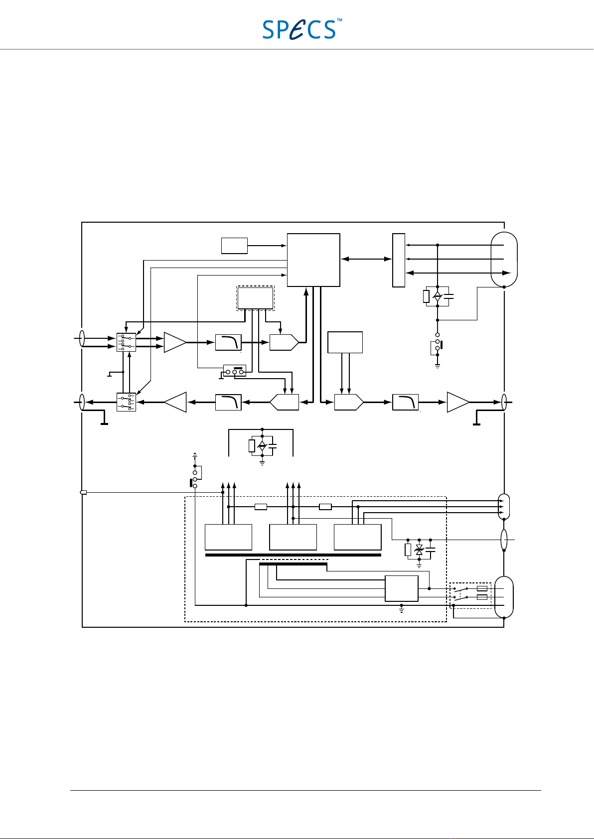
The block diagram of the SC5 is shown in the picture below.
Figure 1: Block diagram of the SC5. Only one analog input and one analog output are shown for clarity.
The SC5 can be divided into the following functional blocks: Analog inputs, analog outputs, fast analog output,
logic, and power supply.
Each analog input (AI) uses an instrumentation amplifier frontend, followed by a 5th order low-pass filter with a
corner frequency of 100 kHz (-3 dB), and then by an 18-bit 1 MS/s ADC. The ADC circuit uses the same
temperature-stabilized voltage reference as the analog outputs. For calibration purposes, the input signal can be
switched to GND, to the reference voltage, or to the corresponding analog output (AO1 to AI1, AO2 to AI2, …,
AO8 to AI8) for all inputs simultaneously. The electronic switch is controlled by software.
AI 1-8
AO 1-8 FAST AO
Fuses
AC input
PE
PE
Line filter
Power
switch
+5V
DGND
-5V
+15V
AGND
-15V
+15V
AUX GND
-15V
Line
voltage
detection
GND BNC
connector
AUX PS
connector
DEVICE SC 01/02/03
connector
±15V auxiliary
power supply
±15V
power supply
±5V
power supply
Power LED
Linear power supply
100Ω100Ω
LPF
LPFLPF
ADC
DAC
AGND AGND
DAC
CPLD
Isolation
1kΩ100n
FPGA DGND
FPGA +5V
Serial communication
PE
PE
PE
10kΩ100n
Temp.
sensor
FAST AO
Vref
Stabilized
Vref
AGND
AGND
U B
AGND
10kΩ1n

SC5 Signal Conversion Instrument Overview
•
12
The eight analog outputs (AO) on the front panel consist of a 20-bit 1 MS/s DAC, followed by a 5th order low-pass
filter with a corner frequency of 40 kHz (-3 dB). Bipolar (-10 V to +10 V output range) or unipolar (0 V to +10 V
output range) can be set individually for each channel by adjusting a jumper placed close to the DAC. The jumper
setting is detected by software. The reference voltage for all DACs is provided by a single precision, temperature
stabilized voltage reference. When the SC5 is switched off, all outputs are clamped to AGND. The output stage is
disconnected from the outputs with software-controlled relays during calibration and start-up. The shield of the
output BNC connectors is connected to AGND.
The fast analog output uses the same DAC as the other analog outputs, with the difference being a separate voltage
reference, and an output stage with a 1st order low-pass filter with a corner frequency of 1 MHz (-3 dB).
The logic section consists of a complex programmable logic device (CPLD) which takes care of preparing and
transferring digital data between the ADCs and DACs in the SC5 and the FPGA in the Nanonis RC5. It also controls
the input selector switches and the output relays, monitors the status of the bipolar/unipolar jumpers of the outputs,
and the temperature inside the instrument. A clock-cleaning circuit provides a clean, low-jitter reference clock for
the digital section and the AD/DA converters.
The SC5 linear power supply generates three preregulated voltages: ±5 V for the digital circuits (and for the power
LED (3) on the front panel), ±15 V for the analog circuits, and ±15 V for the auxiliary power supply. Each supply
branch uses separate secondary windings of the power transformer. The first two power supplies are connected to
protection earth (PE = chassis of the instrument) by two 10 kΩresistors in parallel. The GND of the auxiliary power
supply is connected to AGND over a 100 Ωresistor. DGND, AGND and AUX GND are connected to each other
with 100 Ω resistors. The line voltage is selected automatically.
Front panel
Figure 2: SC5 front panel.
1. Analog inputs: The eight BNC plugs AI1 to AI8 are the analog inputs of the SC5. All inputs can accept
voltages up to ±10 V and are differential. The analog bandwidth is 100 kHz (-3 dB). Please refer to the Analog
Inputs section for more details about the input stage.
2. Analog Outputs: The eight BNC plugs AO1 to AO8 are the analog outputs of the SC5. All outputs can deliver
voltages up to ±10 V and currents up to ±20 mA. The shields of the output BNCs are connected to AGND. The
analog bandwidth is 40 kHz (-3 dB). Please refer to the Analog Outputs section for more details about the output
stage.
3. Power LED (blue): Indicates that the instrument is powered up.
1 2 3
SC5 Signal Conversion Instrument Overview
•
13
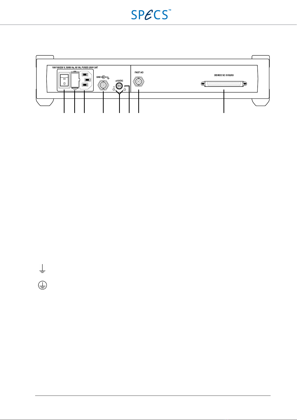
Rear panel
Figure 3: SC5 rear panel.
4. Power switch: Turns the SC5 on and off.
5. Fuse holder: Contains two identical slow blowing fuses, each one connected to line and neutral of the power
supply transformer. Slow blowing 2A fuses (2AT, rated 250 VAC, 5×20 mm) should be used regardless of the
line voltage.
6. IEC power socket.
7. GND BNC connector: The shield of this connector is connected to protection earth (PE), and therefore also to
the SC5 chassis. The inner conductor is connected to the GND reference of the analog electronics (AGND). See
the Electrical ground section for details.
8. Status LEDs (green): Indicate that the positive and negative rails of the auxiliary power supply are providing
the correct voltages (+15 V and -15 V respectively), and are not overloaded. If the external device connected to
the auxiliary power supply connector (9) is drawing too much current (more than 300 mA per rail), the LED of
the overloaded rail will start flashing with a frequency of 5-10 Hz. See the Auxiliary Power Supply section for
details.
9. Auxiliary power supply connector: This connector supplies ±15 V with a maximum current of 300 mA per
rail. It can be used to power external devices like preamplifiers. See the Auxiliary Power Supplysection for
details.
10. FAST AO: This BNC plug provides an additional analog output with a bandwidth of 1 MHz (-3dB). It can
deliver voltages up to ±10 V and currents up to ±20 mA. The shield of the BNC connector is connected to
AGND. For more details, please refer to the Fast Analog Output section.
11. DEVICE SC 01/02/03: This connector is used for the communication between the SC5 and the Nanonis RC5.
The cable for the connection between the two instruments is provided with the SC5.
Symbols:
Earth
Protection Earth
GND
Analog Ground
4 5 6 7 8 9 10 11

SC5 Signal Conversion Installation Guide
•
14
Installation Guide
This installation guide shows how to prepare and power-up the SC5. Following these instructions ensures that the
instrument is working correctly, and that it can be connected to the experiment. Further steps will be explained in
detail in the chapters following this guide.
It will be assumed that the SC5 is controlled using a Nanonis RC5. Please read the RC5 manual carefully before
proceeding.
Content of delivery
When first unpacking the SC5, please check for the following items:
1. Nanonis SC5
2. BNC grounding plug
3. DEVICE RDIO cable
4. Power cord
5. Test protocol
6. User manual
These items are shown in the picture below. Note that the power cord appearance will depend on the country where
the SC5 is used (type J power cord shown).
Figure 4: These items are delivered with the SC5.
1
3
2
4
SC5 Signal Conversion Installation Guide
•
15
Setup
To properly set up the instrument, a square space of at least 40 cm × 50 cm × 10 cm (W × D × H) is required. The
Nanonis RC5 needs an additional height of 25 cm. The SC5 weighs approximately 4.2 kg, and stability of its
supporting table must be guaranteed. It must be possible to access the hardware from the front and the rear in order
to connect all necessary cables. The space has to be dry and kept within the specified temperature range.
Note:Make sure that the power cord is accessible at all times. It must be possible to disconnect the
power cord immediately in case of emergency.
The SC5 requires one power socket (35 VA typical, 60 VA max at 100/120/230 V ±10%, 50/60 Hz ±5%) with
proper grounding. The SC5 is powered by a linear power supply with automatic line voltage selection.
Note:The power cord must be connected to a properly wired and earthed socket.
Note:
Use only the provided power cord or power cords conforming to IEC60227 with a connector
conforming to IEC60320.
Connection to RC5
Only one single cable, supplied with the SC5, is needed as a connection between the SC5 and the real-time controller
RC5. The DEVICE RDIO cable is labelled as SHC68 – 68 – RDIO. Place the SC5 and RC5 at the desired location,
and make sure that the space requirements listed in the previous section are fullfilled.
Note:Please carefully read the RC5 user manual delivered with the Nanonis RC5 before proceeding!
Note:Do not connect the SC5 to a Nanonis RC4. Although no damage to the instruments will occur,
the SC5 will not function.
Note:Only use the supplied DEVICE RDIO cable for the connection between the SC5 and RC5. Do
not use cables labelled as SHC68 – 68 – RMIO or the SC5 will not function.
Make sure that both the SC5 and the RC5 are switched off, but connected to the mains. Connect the DEVICE RDIO
cable to the DEVICE SC 01/02/03 port (11) of the SC5 first, then to the SC 01 port of the RC5, as shown in the
figure below. Always tighten the screws at either side of the connectors.

SC5 Signal Conversion Installation Guide
•
16
Figure 5: Connection of the SC5 to the RC5, when only one SC5 has to be connected. The power cords of both intsruments
have to be connected to the mains first.
Note:
Connect both the SC5 and the RC5 to the mains using the supplied power cords, before
connecting the instruments together!
Note:Make sure that the screws of the DEVICE RDIO cable connectors are tightened, otherwise the
connectors might be damaged. Do not overtighten the screws!
Note:If a single SC5 is connected to the RC5, it must be connected to the SC 01 port at the back of the
RC5. Do not connect it to the SC 02 or SC 03 ports.
Multiple SC5 connection
Up to three SC5s can be connected to a single Nanonis RC5. Follow the instructions given in the previous section for
the connection of the additional SC5 units.
Since the different SC5s are addressed by their port number in the Nanonis software, make sure to label the
instruments on the front panel in order to recognize which instrument is connected to which port.

SC5 Signal Conversion Installation Guide
•
17
Note:If two SC5s are connected to the RC5, they must be connected to the SC 01 and SC 02 ports at
the back of the RC5. Do not connect the second SC5 to the SC 03 port.
Note:The SC5 must be able to dissipate a large amount of heat. It is not recommended to stack three
SC5s on top of the RC5 unless an external source of forced cooling provides a stream of air towards
the SC5 enclosures. It is recommended to use a mixed arrangement with SC5s placed below and above
the RC5.
Caution:Avoid touching the instrument and the BNC connectors if multiple SC5s are stacked on top
of each other since the surface of the instruments and the connectors may become very hot. Switch off
the instrument and let it cool down before touching it.
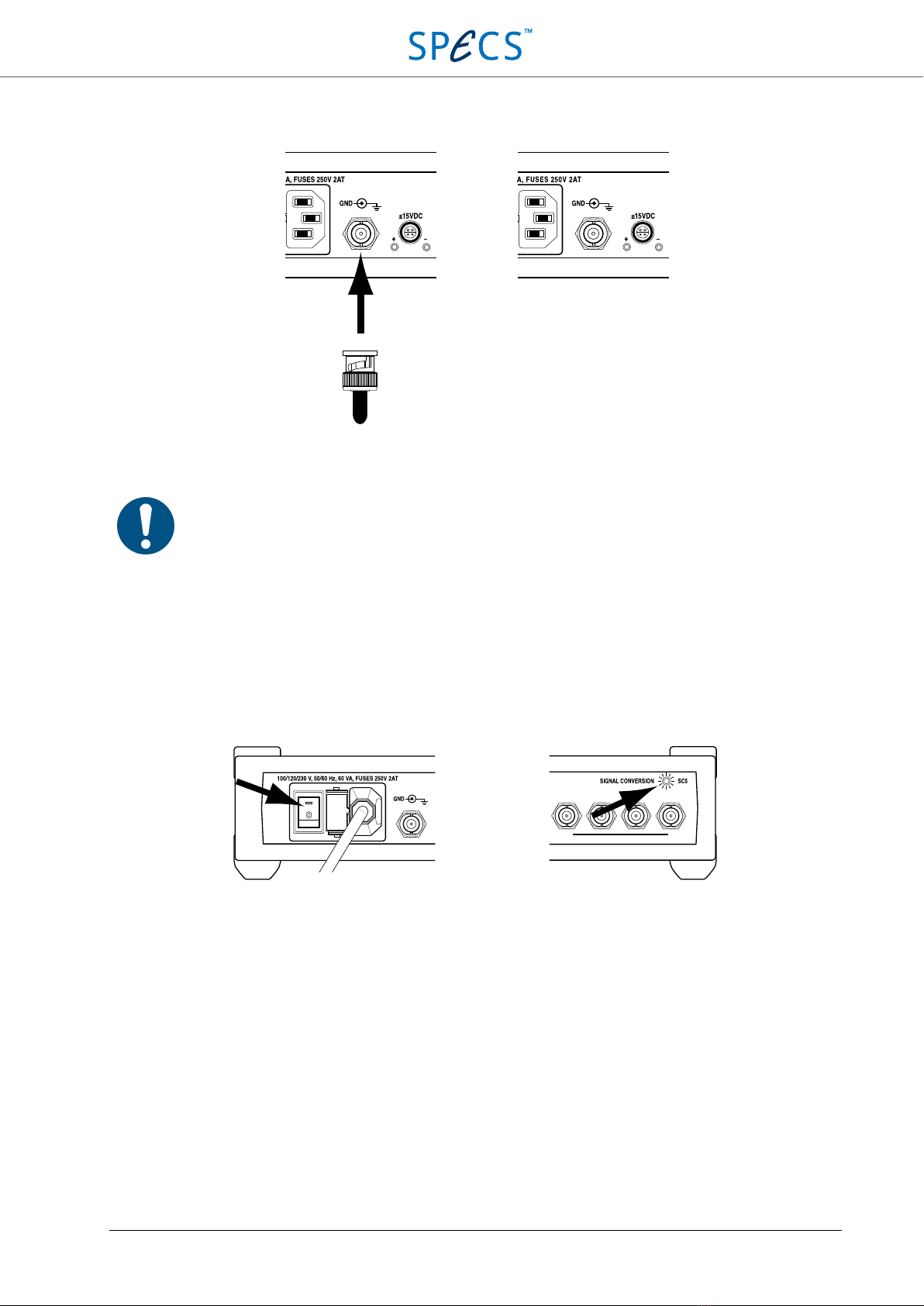
Electrical ground
The SC5 allows for different configurations of the electrical ground. The enclosure of the SC5 is connected to the
protection earth (PE) provided by the AC power line. The ground reference for the analog electronics (AGND) is not
directly connected to PE, but separated by two 10 kΩresistors in parallel. If necessary, AGND can be shorted to PE
by connecting a BNC short plug to the GND BNC connector (7) on the rear panel. By shorting AGND and PE, all
shields of the analog output connectors AO1-AO8 (2) are also connected to PE. Note that all analog outputs are
referenced to the same electrical ground (AGND) and are not floated with respect to each other.
If the experimental setup requires AGND and PE to not be connected together, the GND BNC connector (7) on the
rear panel of the SC5 should be left open. AGND and PE are then separated by two 10 kΩresistors in parallel. In
this case a GND reference for the SC5 electronics must be provided from the experiment over the shield of the
coaxial cables connected between AO1-AO8 (2) and the experiment. The maximum voltage difference between
AGND and PE should never exceed 5 V. The two configurations for the GND BNC connector (7) are shown in the
picture below.
Note that the analog inputs are differential, therefore the shield of the analog input connectors AI1-AI8 (1) is
connected neither to AGND nor to PE. It is not possible to provide a GND reference for the SC5 analog electronics
over the shield of coaxial cables connected to the analog inputs.
The reference ground of the digital electronics (DGND) and AGND are connected together only at the GND star
point. The reference GND of the Auxiliary Power supply is separated from AGND by a 100 Ω resistor. This resistor
cannot be bridged.
The digital GND of the RC5 is completely separated from the GND of the SC5. It is connected to PE of the RC5 by
a 1 k Ω resistor, but PE of the two instruments is connected together only over the power cord, not over the DEVICE
RDIO cable.
The best electrical ground setup depends on the characteristics of the experimental setup, and has to be determined
experimentally. However, a good starting point is to keep the BNC short plug connected at the back of the SC5.
SC5 Signal Conversion Installation Guide
•
18
Figure 6: Electrical GND options for the SC5 depending on the GND BNC connector (7) on the rear panel of the
instrument. Left: BNC short plug connected, AGND and therefore the shields of the analog outputs AO1-AO8 (2) are
connected to PE. Right: No BNC short plug connected, AGND and PE are separated by two 10 kΩresistors in parallel.
Note: The GND BNC connector
should not be used for applying offset voltages to AGND. The
maximum potential difference between AGND and PE should never exceed 5 V, or the power supply
of the SC5 will be damaged.
Powering
Make sure that the SC5 is connected to the Nanonis RC5 as described in the previous section. Turn on the SC5 with
the mains switch (4) located at the back of the unit (see picture below). The power LED (3) will turn on.
Figure 7: Powering of the SC5. Left side: Location of the power switch at the back of the SC5. Right side: LED which will
turn on after powering the unit.
The SC5 is now ready for use. Should the SC5 not turn on as described above, please refer to the Troubleshooting
section before proceeding. If a solution to the unexpected behavior is not listed there, please contact SPECS before
taking any further action.
How to proceed
•Make sure that the SC5 is connected to the Nanonis RC5 as explained in the Connection to RC5 section.
Otherwise switch off the SC5, connect it to the RC5, then switch it on again.
•Turn on the Nanonis RC5
•Start the Nanonis software and make sure that all output voltages are set to 0 V
•Connect the analog inputs of the SC5 as described in the Analog Inputs section
•Connect the analog outputs of the SC5 as described in the Analog Outputs section
•Connect the fast analog output as described in the Fast Analog Output section
AGND and PE
connected at SC5
AGND and PE
disconnected

SC5 Signal Conversion Analog Inputs
•
19
Analog Inputs
This chapter explains how to connect the SC5 analog inputs AI1 – AI8 (1) to other equipment, and explains in more
detail the input stages of the instrument.
Analog inputs connection
The analog inputs of the SC5 can be connected using BNC cables to the signal source of interest, as shown in the
picture below.
Figure 8: Connection of the analog input BNC cables.
Note:The input voltage range of the SC5 analog inputs is ±10 V. Although the inputs are protected
against electrostatic discharge, the absolute maximum applied voltage with respect to AGND must
never exceed ±13 V or damage to the instrument will occur. The limit is valid for both center pin and
shield of the BNC connectors.
There are no external controls for the analog inputs. The gain is set to 1 for all inputs, and input signal selection (see
the Analog inputs schematic section for details) is controlled by software during the calibration procedure.
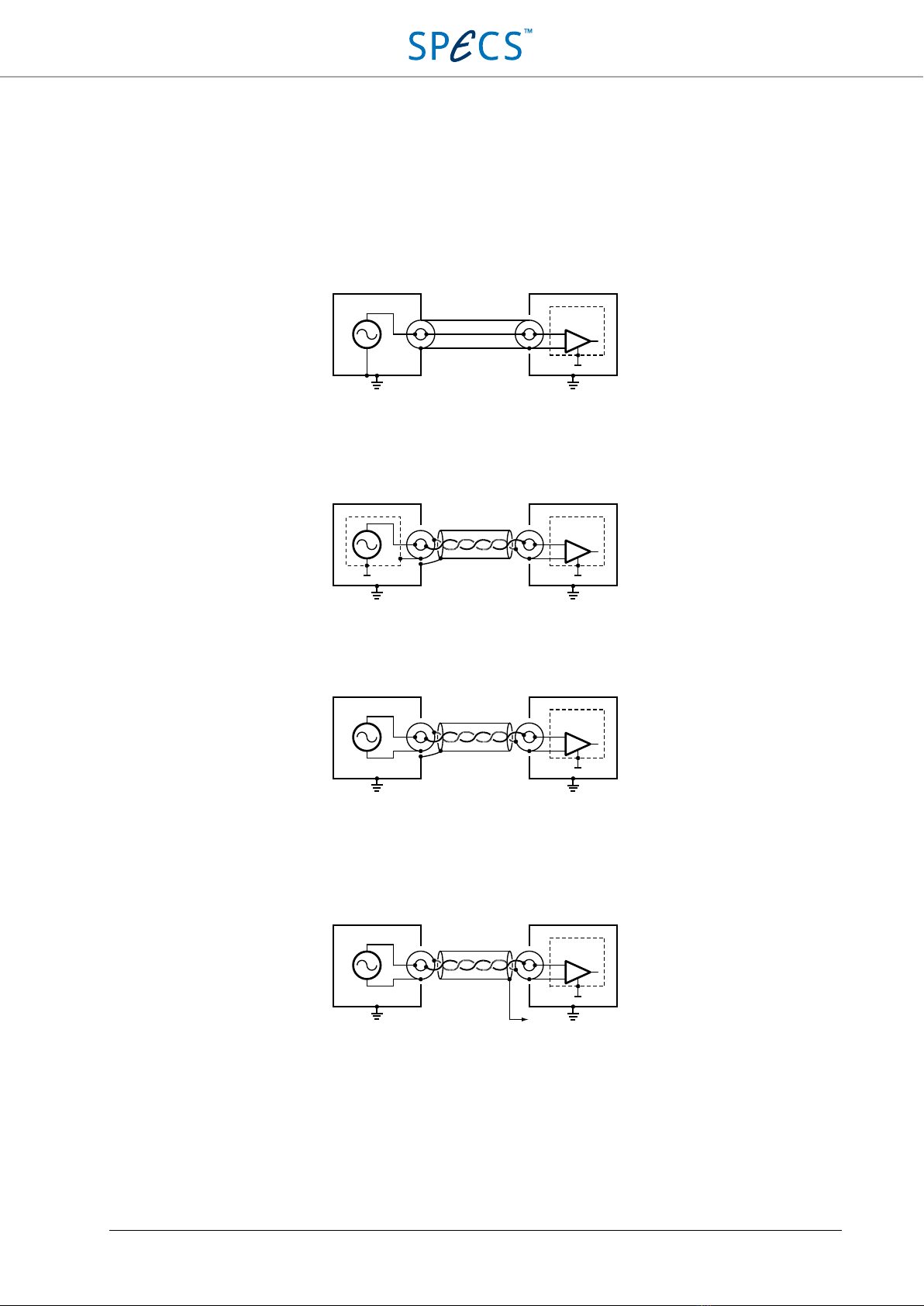
Specific connection options
Connection using shielded twisted-pair cables:The use of coaxial BNC cables as a standard connection is dictated
by their widespread use and general availability in research laboratories. Coaxial cables are, however, not the ideal
solution for low-frequency signals in the frequency range that the SC5 operates. Shielded twisted-pair cables would
SC5 Signal Conversion Analog Inputs
•
20
be the best solution, followed by triaxial cables, but both require dedicated connectors, which would not be
compatible with standard BNC connectors, and also more expensive cabling.
Depending on the signal source, the weaknesses inherent in the use of coaxial cables can possibly be reduced by
preparing shielded twisted-pair cables according to the general rules discussed below. These are suggestions;
improvements will depend on the measurement set-up, and have to be determined experimentally.
Shielded twisted-pair cables should not be used if the signal source is single-ended and referenced to PE, or a BNC
connector with the shield connected to PE is used at the experiment. The situation is depicted below:
Shielded twisted-pair cables can be used if the signal source is single-ended, but is referenced to a different GND
than PE. The GND can be on the shield of the connector (which must then be isolated from PE), or on a separate pin
inside the connector. The situation is depicted below:
Shielded twisted-pair cables should be used if the signal source provides a differential signal. The situation is
depicted below:
When preparing shielded twisted-pair cables, always make sure that the shield is connected to PE only on one side of
the cable. If possible, this should be the experiment side, as shown in the pictures above. If not possible, the cable
shield can be connected to the shield of the GND BNC connector (7) at the back of the SC5. This case is depicted
below:
The connection to the GND BNC connector at the back of the SC5 is shown below:
Experiment SC5
PE
AGND
PE
Experiment SC5
PE
AGNDMeas. GND
PE
Experiment SC5
PE
AGND
PE
Experiment SC5
PE
AGND
PE
To rear
panel
Table of contents


