Storm Audio ISP User manual

ISP
Immersive Sound Processor
Owner’s Manual
Firmware version 3.5r1 onward

The lightning flash with arrowhead symbol within an equilateral triangle, is intended to alert the user to the presence of uninsulated“dangerous voltage“
within the product’s enclosure that may be of sufficient magnitude to constitute a risk of electric shock to persons.
The exclamation point within an equilateral triangle is intended to alert the user to the presence of important operating and maintenance (servicing)
instructions in the literature accompanying the product.
WARNING: TO REDUCE THE RISK OF FIRE OR ELECTRIC SHOCK, DO NOT EXPOSE THIS APPARATUS TO RAIN OR MOISTURE.
DO NOT EXPOSETHIS EQUIPMENT TO DRIPPING OR SPLASHING AND ENSURE THAT NO OBJECTS FILLED WITH LIQUIDS, SUCH AS VASES, ARE PLACED ON THE EQUIPMENT.
TO COMPLETELY DISCONNECT THIS EQUIPMENT FROM THE AC MAINS, DISCONNECT THE POWER SUPPLY CORD PLUG FROM THE AC RECEPTACLE.
THE MAINS PLUG OF THE POWER SUPPLY CORD SHALL REMAIN READILY OPERABLE.
STORMAUDIO LIMITED WARRANTY
StormAudio digital products are warranted to be free from manufacturing defects for two years from the original date of manufacture. The warranty includes parts and labour.
StormAudio will remedy the problem by repair or replacement, as we deem necessary, to restore the product to full performance. StormAudio will pay return shipping only for the
full length of the specific product's warranty.
In the event of a defect or malfunction, contact StormAudio’s repair centers for return authorization. Products must be returned using original packaging material only. Packing
material may be purchased from StormAudio if necessary. This warranty is considered void if the defect, malfunction or failure of the product or any component part was caused
by damage (not resulting from a defect or malfunction) or abuse while in the possession of the customer. Tampering by persons other than factory authorized service personnel or
failure to fully comply with StormAudio operating instructions voids the warranty. This warranty gives you specific legal rights and you may also have other rights which may vary
from province to province and country to country.
StormAudio will only warranty StormAudio products purchased through authorized StormAudio dealers. StormAudio products must be accompanied by a copy of the bill-of-sale
from a StormAudio authorized dealer to qualify for warranty service. The warranty is transferable from the original owner to a subsequent owner as long as a copy of the bill-of-
sale from the original authorized StormAudio dealer accompanies the re-sale. The copy of the bill of sale to any subsequent owner need ONLY include the Name of the StormAudio
Authorized Dealer and the Model and Serial number of the StormAudio product. The warranty will only be honored in the country of the original purchase unless otherwise pre-au-
thorized by StormAudio.
Important Safety Instructions
1. Read these instructions.
2. Keep these instructions.
3. Heed all warnings.
4. Follow all instructions.
5. Do not use this apparatus near water.
6. Clean only with dry cloth.
7. Do not block any ventilation openings. Install in accordance with the manufac-
turer’s instructions.
8. Do not install near any heat sources such as radiators, heat registers, stoves, or
other apparatus (including amplifiers) that produce heat.
9. Do not defeat the safety purpose of the polarized or grounding-type plug. A
polarized plug has two blades with one wider than the other. A grounding type
plug has two blades and a third grounding prong. The wide blade or the third
prong are provided for your safety. If the provided plug does not fit into your
outlet, consult an electrician for replacement of the obsolete outlet.
10. Protect the power cord from being walked on or pinched particularly at plugs,
convenience receptacles, and the point where they exit from the apparatus.
11. Only use attachments/accessories specified by the manufacturer.
12. Use only with the cart, stand, tripod, bracket, or table specified by
the manufacturer, or sold with the apparatus. When a cart is used
use caution when moving the cart/apparatus combination to avoid
injury from tip-over.
13. Unplug this apparatus during lightning storms or when unused for long periods
of time.
14. Refer all servicing to qualified service personnel. Servicing is required when the
apparatus has been damaged in any way, such as power-supply cord or plug is
damaged, liquid has been spilled or objects have fallen into the apparatus, the
apparatus has been exposed to rain or moisture, does not operate normally, or
has been dropped.
15. Do not open. NO USER SERVICEABLE PARTS INSIDE. REFER SERVICING TO
QUALIFIED SERVICE PERSONNEL.
16. For safety and electrical shock reasons, it is recommended to use this device in
a non-tropical environment with temperature not exceeding 45°C and altitude
not exceeding 2000m.
Postal address: George Meyer AV
4844 W. Jefferson Blvd
Los Angeles, CA 90016
PHONE: (310) 820-1113
FAX: (310) 826-9769
E-mail: service@georgemeyer-av.com
E-mail: support.asia@stormaudio.com
STORMAUDIO REPAIR SERVICE in USA
STORMAUDIO SUPPORT in ASIA:
contact your local distributor or
CHECK OUR WEB SITE: www.stormaudio.com
PHONE STORMAUDIO DIRECTLY: +33 249 623 043
Postal address: StormAudio France
15 rue Olympe de Gouges
44800 Saint-Herblain
France
STORMAUDIO SUPPORT & REPAIR SERVICES outside USA and ASIA:
PHONE: (415) 766-6417
E-mail: support.usa@stormaudio.com
STORMAUDIO SUPPORT in USA

Table of Contents
Important Safety Instructions ................................2
Front Panel ..............................................................4
Rear Panel................................................................4
General.....................................................................6
Welcome ............................................................6
Included In The Box...........................................6
Features .............................................................6
Shipping Box and Packing Material..................6
Installation...............................................................6
Ventilation .........................................................6
Connecting to A/C Power..................................6
Connecting to Network.....................................6
Connect IR Interface (Optional)........................6
Connect Source Components...........................7
Connect to Display ............................................7
Connect Audio Outputs.....................................7
First Run...................................................................7
Power On ...........................................................7
Get Network Access...........................................7
Default Passwords.............................................7
Web UI Header Diagram..........................................8
System Settings.....................................................10
Input Settings ........................................................12
Building a Theater - Dening Channels................14
Proles...................................................................15
Test Tone Generator ..............................................16
Individual Channel Adjustments ..........................17
Expert Bass Management .....................................19
Output Mapping ....................................................19
Multi-way Loudspeaker Setup..............................20
Channel EQ ............................................................21
Child Theater / Sub Theater..................................23
Zones .....................................................................23
Dirac Live ...............................................................24
Settings Menu........................................................27
Triggers ............................................................27
Parameters ......................................................28
Audio/Video General Delay per AV Zone ........28
System Setup...................................................28
Front Panel ......................................................28
IR Function Assignment & Commands...........28
Presets ...................................................................29
Monitoring .............................................................30
Web UI Remote Control.........................................31
iPad App.................................................................32
Specications........................................................33
Audio Specications .......................................33
HDMI Specications........................................33
Options ............................................................33
Weight and Dimensions ..................................33
Installation Notes ..................................................34
Our policy of continual product improvement means that StormAudio reserves the right to modify the technical specifications of its products without notice.
Product may vary from images.

4
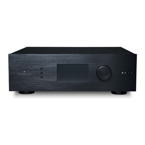
Front Panel
1. Power Button
Use this button to toggle the ISP between ON
and STANDBY. Note that the rear panel switch
must be on for the unit to operate.
2. Exit
When navigating the front panel menu, press
Exit to go back.
3. Enter
When navigating the front panel menu, press
Enter to conrm a selection.
4. Edit
Press Edit from the home screen to enable state
changes in the ISP. Use the Volume combo
knob to navigate.
5. Display
The front panel display shows various
information about the unit. It is not a touch
screen.Variousparameterscanbe setaccording
to instructions “Front Panel” on page 28.
6. Volume
The default state for the knob is to control
volume in the selected theater. Press the knob
to mute audio. When in Edit Mode, you can use
the knob to navigate between elds.
Rear Panel
7. HDMI
7 HDMI inputs and 2 outputs are available, with
two versions “7+2” or “7+2 eARC”.
• 7+2 eARC: All HDMI inputs and outputs are
HDCP 2.2 /HDMI 2.0 compatible. Outputs
are mirrored. HDMI Output 1 is eARC and
ARC capable.
• 7+2: All HDMI inputs are HDCP 2.2
compatible, but only inputs 5-7 operate at
HDMI 2.0 speeds by default. Outputs are
mirrored. HDMI OUT 1 is 1.4a compatible.
HDMI OUT 2 is HDMI 2.0 4K compatible.
See “Specications” on page 33.
8. Power Inlet / Fuse Socket / Mains
Switch
Mains power is applied to the ISP here. Ensure
the fuse installed matches requirements of
your locality. The rear panel switch must be ON
for the unit to operate.
9. Network
The ISP must be connected to a network for
setup. It is recommended to be connected for
operation. Speed is 100 Mbps. Use CAT5e or
better cable.
10. USB
Two USB ports are provided to which a USB
microphone may be optionally connected RTA
function. Or, the USB ports may be used for
service.
1
2 3 456

ISP Immersive Sound Processor
5
11. IR
IR input and output are provided via 3.5mm
jacks for optional control via IR remote.
12. Trigger Out
Four separate trigger outputs are provided to
control power of certain connected devices.
See “Triggers” on page 27 for conguration
information.
13. Digital Inputs
Three digital coax and 3 TOSLINK optical digital
inputs are provided for connection of legacy
digital sources.
14. Analog Input
Eight RCA inputs are provided and can
be used as 4x stereo pairs or 1x 7.1 input.
When connected as a 7.1 input, the channel
assignment is as follows clockwise from top
le: LF, CF, LS, LB, RB, RS, SUB, RF.
15. Downmix Output
A stereo pair of XLR outputs is provided as a
dedicated 2 channel downmix output. These
outputs produce a stereo downmix of whatever
audio is playing in the selected theater. To
congure, see “Parameters” on page 28.
Downmix may be enabled for select presets.
See “Presets” on page 29.
16. Analog Output
Sixteen XLR analog audio outputs are provided
by default which are fully assignable to
theaters or zones. See instructions starting
with “Building a Theater - Dening Channels”
on page 14. Outputs may also be remapped.
See “Output Mapping” on page 19. Pin 2 hot.
17. Optional Analog/Digital Output
Three optional modules are available for this
slot to provide either 4ch XLR analog outputs
or the 32ch as digital outputs with one module
supporting the AES/EBU format over 4x RJ45
connector and one module supporting the
Audio Video Bridging (AVB) Audio over IP
transmission.
18. Optional Alternate Analog Output
Two optional modules are available to provide
16ch additional outputs that can be used
either as Alternate (Balanced DB25 outputs) or
Alternate/Duplicate Theater creation.
19. Option Analog Output
One optional module is available to allow for
up to 16ch additional analog audio outputs,
oering total 32ch XLR outputs to the ISP.
20. Optional Digital Input
One optional module is available to allow for
up to 16ch of AES/EBU audio streams to be
provided through 2x RJ45 connectors. See
“Settings” on p28.
21. Rear Panel Fan
From time to time, the ISP may automatically
turn on the fan to draw cool air through the ISP
and out the back. Do not obstruct the fan or
any airow vents on the chassis.
9 10 12 13
18
21
14 15 16
11
7
8
17
20 19

6
General
Welcome
Thank you for your purchase of a StormAudio
ISP Immersive Sound Processor. The ISP has
been designed to provide state of the art audio
performance with immersive surround formats and
legacy surround formats alike. Innovative hardware
and soware make it possible to customize theaters
of up to 32 channels. Its modular nature allows for
matching any inputs / outputs requirements as
well as an upgrade capability for many years to
come.
Included In The Box
• This Owner’s Manual / Installer Guide
• Power cable for your locality
• Rack mount ears (requires T20 Torx screwdriver
to mount)
• UMIK-1 USB microphone and extension for RTA
and StormMonitoring feature.
Features
StormAudio ISP includes the following features:
• 7 Input / 2 Output HDMI switch, 3 TOSLINK and
3 RCA S/PDIF legacy digital inputs plus soware
congurable analog input (7.1 or 4x Stereo)
• Mandatory network connectivity for control
and rmware updates.
• Up to 32 soware congurable outputs (analog
or digital) + Downmix L/R XLR pair
• Up to 16 congurable digital inputs
• 4 programmable trigger outputs
• IR control
• Available control modules for 3rd party
automation systems available on the Client
Portal at http://www.stormaudio.com
Shipping Box and Packing Material
Please keep the original shipping box and all
packing material. In the unlikely event you have a
problem and must return it for service, you must
use the proper packing material as the unit is
not insurable by carriers otherwise. Replacement
packing materials is available from StormAudio for
a small fee.
Installation
Prepare your installation site by following the steps
below: Consult page “Rear Panel” on page 4
for rear panel diagram indicating location of key
connections.
1. For non North American models that are
delivered with a fuse attached to the AC cord,
install the fuse before plugging the unit into
mains power.
2. Ensure your electrical circuit has a good
ground connection with all audio equipment
connected to the same ground node to avoid
noise or hum due to a ground loop.
3. Prepare attached equipment such as display or
projector, audio ampliers, speakers, network
switch and associated cables.
4. Network should be running a DHCP server to
enable the ISP to obtain an IP address.
Ventilation
The ISP is a cool-running line level component. It
generates far less heat than ampliers and many
other components. It can be safely placed inside
furniture or an equipment rack. However, it should
not be tightly enclosed. Some airow is desired.
Note that the rear panel fan needs to be able to
circulate air especially when the ISP is under heavy
load.
Connecting to A/C Power
If necessary, install the included fuse into the fuse
socket. Plug the IEC-320 C14 end of the power
cord into the ISP, then plug the other end into an
approved and grounded A/C receptacle.
Connecting to Network
Using at CAT5e or better cable, connect the ISP to
your local area network. See “Get Network Access”
on page 7 to identify IP address.
Connect IR Interface (Optional)
Should you choose to use an IR interface, you will
need to connect an IR receiver to the IR Input of the
ISP.
Connect Source Components
Legacy digital sources can be connected to the

ISP Immersive Sound Processor
7
digital inputs 1-6. Stereo or surround analog
sources can be connected to the Analog Inputs
section. Analog input conguration is dened at
“4. Main Audio In” on page 12. HDMI sources can
be connected as well.
Connect to Display
Connect your displays using HDMI outputs. Note
that outputs are mirrored (same content):
• 7+2 eARC: eARC/ARC is only supported in
HDMI OUT 1, so the recommended output
to interface with a TV receiver. HDMI OUT 2
is recommended for Projector interface.
• 7+2: HDMI OUT 1 supports up to HDCP 1.4
while HDMI OUT 2 supports HDCP 2.2. Use
HDMI OUT 2 as your primary output port.
Should no picture appear on HDMI OUT 1,
troubleshoot EDID conicts.
Connect Audio Outputs
If you choose to connect your outputs at this step,
take note of which output number is routed to each
channel so that you can map them appropriately in
a later step. Otherwise, when you setup the theater
using the web UI, the default outputs will be
noted for you. At that point, you can connect your
ampliers based on the default output channel
mapping.
First Run
Upon rst run, you must congure the ISP according
to your specications using the web based user
interface. There is no on-screen display or provision
to congure the unit using the front panel.
Power On
Turn the main switch on the rear panel to the ON
position.
The front panel display will show the StormAudio
logo for a few seconds, then will go blank as the
ISP enters sleep mode. The power LED will show
steady red.
Once in sleep mode, press the front panel POWER
button. The ISP will begin the startup sequence.
During the Initialization process (about 30s) the LED
will blink green until the unit is ready with a steady
green LED. Initialization process can be shorten at
the cost of more standby power consumption. See
“Settings” on p28 to adjust this.
Get Network Access
Press and hold the EDIT button for about 3 seconds.
The display will show a list of information including
the IP address at the top which was assigned by
DHCP. Note this address.
Note: In case the unit is not in DHCP mode, and you need to
restore DHCP mode from the front panel, follow the above
steps, then press and hold EDIT for a few seconds more until
a message appears asking for conrmation of this action.
Conrm by pressing the ENTER button
Using a web browser on a device (laptop preferred)
on the same network, enter this IP address in the
address bar of your web browser.
Note: Only one instance of control via web UI can be opened
at a time. If a window is already accessing the I.ISP web UI, a
message will ask you to close one. Browsers supported: Edge
(Windows), Safari (macOS) and FireFox, Chrome (Windows,
macOS et Ubuntu). Others might show issues.
The ISP home page will be shown.
Selecting Remote Control will give access to the
end user remote control functions. No setup
parameters can be changed here.
Select Expert Setup to gain access to the setup
portion of the web UI.
Default Passwords
Note: In case you have forgotten the Expert User or Installer
password, it is possible to reset them to the default values
by rst accessing the Info screen (see “Get Network Access”
on page 7). Then press and hold EDIT and EXIT buttons
together. Press ENTER to conrm when prompted.
The Expert Setup area has two levels of access:
Expert User and Installer. Expert user gets access
to portions of the menu dened by the installer.
Installer gets full access to setup. Use this level to
perform the conguration.
The default password for full access to the setup
menu is ‘installer’. Enter the password and press
connection to enter the setup menu. Default
password for Expert User is ‘expert’.

8
Web UI Header Diagram
1. Persistent Remote Control Bar
This area provides access to change some
settings without having to access the remote
control page. Change Source, Preset, Theater,
Proles within each theater, and Surround
modes.
2. Volume Control
Volume control is provided without having
to access the Remote Control page. The + / -
buttons adjust volume in 1dB increments. The
++/-- adjust volume in 3dB increments. Mute
cuts all sound. Dim attenuates the volume by
the amount specied in “Parameters” on page
28.
3. Conguration Section
• System: indicates information about the system
such as rmware version, any installed licenses,
network parameters. System conguration backups
and rmware updates are also done here.
• Inputs: Congure input names, map physical inputs
to source components, and make input dependent
settings.
• Main Speakers: Congure primary theater, child
theaters, audio/video and audio only zones. This is
where you map analog outputs to physical channels.
• Alternate Speakers: If the optional 16 channel
RCA/DB25 Output Card is installed, you will see an
Alternate Speakers tab to the right of Main Speakers.
Setup for the Alternate Speakers is identical to that
of Main Speakers.
• Settings: Congure trigger behavior, HDMI, IR, and
other system wide parameters.
• Presets:Buildpresetsthateasilyrecallcombinations
of Theaters, downmix zones, EQ proles, triggers and
surround upmix behavior. Presets oer customers
the easiest way to place their system into modes for
dierent types of listening.
• Monitoring: This StormMonitoring page gives
real time and logged statistics on the health and
performance of the ISP which can be accessed via
the local network or via remote network access
which makes system diagnostic endeavors less
speculative and much more concrete.
• Remote Control: A copy of the page available to
anyone logging into the web UI regardless of their
credentials level. The only dierence between this
page and the one available without logging in is that
the Persistent Remote Control Bar remains at the
top.
4. Trigger / Generator / Power / Restart
• Trigger: Any triggers congured in Settings
(Conguration Section) for Manual Switching appear
here giving you easy access to activate or deactivate
these triggers with a click. Green indicates that the
trigger is in the active state. White indicates that it
is not.
• Generator: When white, the ISP built in noise
generator is not active. When green, it is active. This
is an indicator. The generator cannot be switched on
from here.
• Power: Switch the unit from standby to on status
from here. Green indicates that the unit is powered
on. White indicates standby.
• Restart: Should you need to restart the ISP, you can
do so from this switch.
12345 6

ISP Immersive Sound Processor
9
5. Log Out
Pressing Log Out will return you to the web
UI home page. To access the installer menu
or expert user menu, you must log in with the
appropriate password again. Otherwise, you
only have access to the remote control.
6. Help
A unique feature of the ISP web UI is the
comprehensive built in help function. With
this switched to ON, every function on the web
UI features a which can be hovered over
with a mouse to reveal a description of that
specic function. Some functions have a
which indicates important information. These
warning indicators are present regardless of
whether Help is engaged or not.

10
System Settings
1. Processor Status
This area indicates the model number, serial
number, rmware revision and HDMI card
version. You can also download logs which can
be sent to us for diagnostic purposes.
2. Options and Licenses
This area indicates which of the Optional
Modules and Soware Features are currently
installed.
3. System Backup & Restore
• Export Parameters: Generates a spreadsheet
indicating the mapping of the output channels.
• Backup Conguration: Generates a backup
le of the entire current conguration of the ISP
making restoring settings easy aer replacing a
unit or recovering from a system reset event. As a
dealer, you are advised to perform this step aer
completing setup and archive the settings on behalf
of your customer.
• Restore Conguration: Permits uploading of the
le generated by the step above. This overwrites all
current settings with the data contained within the
backup le, including the Dirac lters.
• Factory Reset: Resets the ISP to default
conguration but retains current rmware version.
• Remote Upgrade: Use this tool to update the
rmware of the ISP. New rmware is made available
from time to time and can be found on the Client
Portal at http://www.stormaudio.com. Firmware
upgrades are never required and should be
considered optional unless advised otherwise by
StormAudio support sta.
4. Network Settings
Displays current settings. By default, this
is populated by the network DHCP server.
DHCP Auto button is grayed. To use a static IP
address, click DHCP Auto to disable (turns grey)
and populate IP Address, Gateway, Netmask,
and DNS elds manually. If an ISP has been set
to static IP mode and will no longer connect to
the network, see “Get Network Access” on page
7for instructions on resetting the network
settings to default DHCP mode.
5. Password Management
The ISP has 3 levels of access. Remote Control
requires no password and no access to settings.
Installer has access to all settings. Expert is an
intermediate level that has access to settings
assigned by Installer. Those settings are dened
in the Access Management area at the bottom
of this page. The default passwords are:
Installer: installer
Expert User: expert
If you are a dealer or custom installer, you
are advised to change these passwords and
document them. Similarly, if you are a client
and wish to lock other users out of settings, you
may wish to change default passwords as well.
If you have forgotten your passwords and
have locked yourself out of the ISP, you can
reset them back to default by following the
procedure “Default Passwords” on page 7.
1
5
6
3
4
2

ISP Immersive Sound Processor
11
6. Access Management
This area permits a user logged in as installer
to assign access to specic setup functions
to the Expert User. For example, if the ISP is
installed at property with technical sta, the
installer may wish to permit the Expert User to
make changes to the inputs for the purposes of
installing a new source, but restrict their ability
to make changes to speaker EQ, apply rmware
updates, etc. Any setup menu marked “Y” in
grayed is accessible to a user with the Expert
User password.
Note that aer making any changes,
you must press the SAVE button near
the top right of the screen or you will
loose your changes.

12
Input Settings
The ISP permits the installer to create access to
sources in a very intuitive way for the end user. The
installer is advised to title inputs thoughtfully and
without ambiguity. No longer must an end user
remember which physical input is attached to a
particular source component. Further, only inputs
specically congured as ACTIVE will be available
from the remote control. Finally, multiple inputs
can be created from a single source component
for the purposes of loading separate settings. For
example, you may have an input titled ‘CD Music’
that accesses a Blu-Ray player attached to HDMI 7
that by default downmixes everything to stereo and
another input titled ‘Blu-Ray Movie’ that accesses
the same source component but upmixes all audio
to Dolby Surround.
1. Active
Any input with a grayed Y is accessible from
remote controls. To disable access to an input,
click the Y and it will change to an N and gray
out the entire row thereby disabling access to
this input. You are advised to disable any input
with no source component attached.
2. Input
This is the name of the input that will appear
in remote control applications. By default, the
name is the same as the default audio input.
You may type in this box and change the
name to something more intuitive. Supports a
maximum of 10 characters.
3. Video In
For any given input, you can map separate
video and audio inputs except that when the
audio input is an HDMI input, the video input
must be the same HDMI input. None may also
be chosen when no video is desired.
4. Main Audio In
For any given input, you can map separate
video and audio inputs for the Main Theater
audio path, except that when the audio input
is an HDMI input, video must be the same HDMI
input. None may also be chosen when no video
is desired. Note that the analog input matrix
may be selected as a particular stereo pair or
as a 7.1 input.
5. Zone2 Audio In
The ISP oers a dual source selection so that
you can have one source playing in the Main
Theater dened in point 4 above and another
source playing in the other dened Audio Zones
(see “Building a Theater - Dening Channels” in
p14 for the Theater and Audio Zones creation).
The Zone2 Audio input cannot include HDMI
selection. For device with HDMI connection,
It is recommended to connect and dene an
Input with two physical connection to the ISP
such as HDMI for Main Audio In and SPDIF/RCA
for the Zone2 Audio In. Doing so, selecting this
Input will take the correct physical connection
1
2
3
4
5
6
7
8
9

ISP Immersive Sound Processor
13
automatically depending on the Theater or
Zone playback.
6. Preferred Upmix
On a per input level, you may choose to engage
a particular upmixer, or leave the option set
to none. This setting overrides any preferred
upmix dened as part of a preset. So, if a preset
is to be used in conjunction with this input, and
that preset includes specifying an upmix, leave
this setting to None.
7. Trimmer
Each input may have the audio attenuated by a
specic value in an eort to level match source
components and yield an expected volume
level in the room regardless of source selected.
No gain can be applied, only attenuation. The
range is -30dB to 0dB with 0.1dB precision. The
+ and - buttons adjust the value by 0.5dB.
8. AV Delay
Each input may have a synchronization delay
set between video and audio. This range is
0-100ms in 1ms increments.
9. Triggers
The ISP can trigger connected devices on using
the 4 DC trigger output jacks on the back when
a specic input is selected. Most commonly,
this is used to power on the source component
connected to a specic input. To enable this
feature, the desired trigger must be set to Auto
Switching: Enabled on Input in the Settings
menu. See “Triggers” on page 27. To engage
a trigger based on input, click the gray N. It will
turn into a grayed Y when the trigger will be
activated upon selection of that input.
Note that aer making any changes,
you must press the SAVE button near
the top right of the screen or you will
loose your changes.

14
Building a Theater - Defining Channels
To assign analog outputs to particular channels,
you must build a theater. A theater may occupy as
few as 2 channels or as many as 16 or 32 depending
on the Optional module assembled. There are over
90 options for theaters. Any channels le over may
be assigned to secondary multi-channel theaters, 2
channel A/V zones, audio only zones, mono zones
or headphone zones. A physical output can only be
assigned to one theater or zone.
To assign channel outputs, you must rst build
a Theater or Zone. Theaters are multi-channel
systems. Zones are either 1 or 2 channel audio or
audio/video zones. Any theaters or zones created
appear to the right and are listed by their names
which you assign. By default, the ISP ships with a
2 channel theater congured. To build your own,
delete this theater and create a new one.
Click EDIT, then DELETE. Click OK to conrm. You
will be returned to the Main Speakers page.
1. Create Theater
Click Create Theater to build your new theater.
Theater 1 will appear to the right of the Create
Theater button. Click Congure to proceed.
2. Select Speaker Layout
All possible loudspeaker layouts based on
available channel count are listed. A shorter
list “Recommended by StormAudio” is listed
by default and contains most commonly used
options. Click All to see all possible options.
Denitions are titled by channel count in the
following order, “Base Layer . LFE . Height
Layer . Top Layer”. For example, 9.1.0.6
would feature 9 ear level speakers, 1 sub
channel, 0 height speakers (common only
for Auro3D layouts), and 6 ceiling speakers.
For each denition, you can use the matrix to see
how compatible that layout is with each of the
3 codecs and which possible speaker locations
are occupied. To reduce ambiguity, you can also
click VIEW to see the layout visualized in a room.
1

ISP Immersive Sound Processor
15
Click Select to choose your desired speaker
layout.
3. Rene Theater Denition
Once you select your desired speaker layout,
you have the option to rene certain settings.
• Ways per Speaker (LCR): For the front le, center,
and right speakers, you can dene multi-way active
loudspeakers up to 3 ways per speaker.
• Surround Layers: Optionally duplicate surround
channels to increase coverage in large rooms to
match seating row count.
• Subwoofers: Though there is only 1 LFE channel,
you can specify the number of channels which will
drive discrete subwoofers. Unlike daisy chaining
subwoofers, each channel can have its own settings
and EQ. For installation without Subwoofer, put “0”.
• Enabled Mode Layers: When using customized
Dolby Atmos up-ring loudspeakers in place of
ceiling mounted top layer speakers, choose whether
these speakers are mounted on top of the Front,
Side or Back loudspeakers.
• Custom Channel Duplicator: Check this box and
enter the number of duplicates for any channel in
the theater.
• Phantom Center: If no discrete center channel
speaker is present, checking this box will remove the
center channel from the theater denition.
Any changes made here can be visualized by
clicking the PREVIEW button. Once your theater is
dened properly, click SAVE to proceed. You will
then be directed towards a page where you can
make speaker based adjustments.
Profiles
For each Theater, Sub-Theater, and zone, you
can save multiple proles for dierent listening
preferences. Proles can be recalled as part of
presets “Presets” on page 29. A prole includes
the following information: Speaker denition
(multi-way, levels, delays), bass management,
manual EQ, and Dirac lter design if applied.
Some clients have dierent EQ proles based on
the type of content they listen to e.g. movies vs.
music.
1. Rename
By default, one prole is created called New
Prole 1. You can rename this to something
more descriptive.
2. New
Click New to build a new prole from defaults.
3. Duplicate
Build a variation on a saved prole. This is
especially useful if you have a prole designed
with Dirac Live. Since you cannot edit Dirac
reference proles directly, you can build a
duplicate and edit that duplicate.
4. Save
Aer any changes to a prole or creation of a
new one, you must SAVE your changes.
Sub
Base
Height
Top
1
2
34

16
Test Tone Generator
The ISP includes a highly congurable test tone
generator which can be used to help manually
calibrate channels.
1. Generator
Click this button to turn on the tone generator.
It will automatically start with Group 1. The
channels outputting sound will be highlighted
in green.
2. Setup
Unlike traditional generators, the ISP will not
strictly play tones one channel at a time. Click
Setup to assign channels to groups. Each
group may contain one or more channels. For
example, if you have 2-way active loudspeakers,
you may wish to group the high frequency and
low frequency component of each into one
group.
3. Noise Selection
Choose the type of noise or tone created by the
generator.
• Sine: Generates a sine wave at the frequency
specied.
• Pink Noise: Generates full bandwidth pink noise.
• Pink Noise 400-4kHz: Generates pink noise band
limited to one decade. This is particularly useful
when setting relative levels between channels
with dramatically dierent useful bandwidths.
Remember SPL meters measure not only sound
pressure but also bandwidth.
• External: it is possible to use an external noise
generator connected to one of the ISP dened input.
This is usually required when using an external room
calibration tool providing its own stimuli (Room EQ
Wizard is one of them, see “REW integration”, p22).
4. Gain
The gain gure can be set so that the noise
generator operates at a level at or below that
of a normal source playing at 0dBFS. Default is
0.1 (-20dBFS).
5. Group
When the noise generator is active, use this
function to play the noise through dierent
groups dened in “2. Setup”.
6. RTA
When a USB microphone (such as the optional
Theater Acoustic Diagnostic Kit) is connected
to the ISP, you can use the Real Time Analyzer
to visualize the response of loudspeaker
groups in the room. Note that the built in RTA
is not accurate enough to use for calibration,
but is useful for getting a good idea of the
1
2 3 4
5
67
10
9
11
12 15
16
13 14
8
17

ISP Immersive Sound Processor
17
approximate response of the system. Maximum
level of the capture can be set by adjusting Mic
Ref Level. Graph vertical scale can be changed
from Logarithmic (default) to Linear.
7. Dirac
See “Dirac Live” on page 24 for use of Dirac
Live Calibration Tool.
8. Volume Reference
It is good practice when calibrating systems
to always work at a reference level such as
85dB C-weighted. Before activating the noise
generator, make sure the master volume is at
a low level. Set and recall a reference master
volume value. Click SET once you have dialed
the value you’d like to store. Click RECALL to
quickly return to that value.
Individual Channel Adjustments
Once your theater is dened, each channel can
be individually ne tuned. The theater can also be
renamed, and a child theater can be created which
enables stereo le, right, or mono audio to be
routed to existing channel assignments.
9. Channel Status
Each channel is enabled by default. If for some
reason this channel needs to be disabled, click
the ON button. It will turn to OFF and audio will
no longer be routed to that channel. Note that
audio will not be re-routed to other channels.
Channel status is set per Theater / Zone and is
not stored as part of a prole.
10. EQ
Each channel can have up to 20 lters cells
congured selecting the wheel icon. Channel
EQ can be bypasse by selecting ON/OFF.
See “Channel EQ” on page 21 for detailed
EQ options. EQ settings are stored as part of
proles.
11. Signal
Indicates which signal is routed to this output.
Should you desire to remap signal routing, you
can do so with Output Mapping. See “Output
Mapping” on page 19 for details.
12. Channel Name
Customizable name to easily identify each
channel. By default, these are named for
the signal sent to each channel. You may
decide to change these to speaker model or
another unique identier. Maximum allowable
character count is 24.
13. Size / Filter
Identify each channel as either Large, Small,
or Large and Sub. When a channel is set to
Large, no bass is redirected from this channel
to the subwoofer. Use this setting when the
loudspeaker has suicient bandwidth and
output capability to reproduce suicient
bass. When a channel is set to Small, bass in
this channel is redirected to the subwoofers
according to the Frequency and Slope for that
channel. Large and Sub is a special case that
not only allows that channel to reproduce full
bandwidth audio, but also duplicates bass in
that channel to the subwoofer(s) according to
the Frequency and Slope for that channel.
Subwoofer channels have specic settings. By
denition, subwoofers have limited bandwidth
and some are more limited than others.
• Low Pass LFE: When this is set to ON, the subwoofer
channel has a low pass lter applied according to
that channel’s Frequency and Slope. This is designed
to limit the channel’s ability to reproduce the upper
portion of the bass spectrum. This is usually done to
prevent the subwoofer from contributing midrange
distortion.
• Subsonic SUB: When this is set to ON, a high pass
lter is applied to the channel which restricts the
subwoofer’s ability to reproduce very deep bass
according to the frequency and slope dened for
that channel. Many subwoofers, especially smaller
models do not have the amplier power or driver
displacement required to accurately reproduce very
deep bass. By actively ltering very deep bass away
from the subwoofer, it is better able to reproduce
bass within it’s useful bandwidth.

18
* Items 14 and 15 pertain to Standard Bass
Management Mode in which the crossover point
and slope dened apply to both the high pass and
low pass sides of the lter equally. For Expert Bass
Management, see “Expert Bass Management” on
page 19.
14. Frequency
When the channel is set to Small or Large and
Sub, the Frequency denes the point below
which bass in this channel is routed to the
subwoofer(s). Note that the frequency is the
-3dB point along the slope dened in the next
column and is not an absolute cuto point.
15. Slope
The rate at which bass is ‘crossed over’ into the
subwoofer when the channel is set to Small or
Large and Sub. LR 12dB and LR 24dB are 2nd
order and 4th order Linkwitz Riley alignments
respectively.
16. With LFE
When a channel is set to Large or Large and
Sub, this channel can optionally reproduce
LFE bass which would normally be the sole
responsibility of the subwoofer channels.
When set to None, no LFE will be mixed into
this channel. When set to a gure between 0dB
and -20dB, LFE bass attenuated by that gure
will be mixed into this channel. This feature is
useful when the main channels have suicient
bandwidth AND dynamic range to support the
subwoofers in creating an appropriate amount
of bass sound pressure in the room.
* Items 19-22 apply to settings found in the ‘Delay,
Level, Limiter, and Phase’ section.
17. TiltEQ
For speakers behind a motorized screen for
example, you might need to change their
“audio brightness” depending on the screen
position up or down. TiltEQ allows the sound
to be darker of brighter.
18. Delay units
Choose whether to measure channel delays in
meters (default), feet, or milliseconds.
19. Delay per Channel
Each channel should have distance/delay set
beteween that loudspeaker and the sweetspot.
You can dene this in meters (default), feet, or
ms depending on your setting in 16.
20. Level
Set the level of each channel in between
-100dB and +12dB in 1dB increments. Best
practice is to set other channels to a negative
gure relative to the loudest channel to avoid
clipping when possible. Global gain makeup
can be applied to the theater when the relative
level of the theater is too low (usually a result of
a high degree of correction due to Dirac Live’s
mixed phase lters). Use global gain makeup
judiciously to avoid clipping.
21. Limiter
To prevent distortion due to loudspeaker
overdriving or amplier clipping, you may wish
to engage a limiter on a channel. When enabled,
a compressor will attenuate audio above the
threshold set by the Limiter Value for that
channel back down to that value. For instance,
if the limiter is enabled and set to -3dBFS, any
21
22
20
19
18

ISP Immersive Sound Processor
19
audio that exceeds -3dBFS will be reproduced
at -3dBFS. By their nature, limiters are not ideal
acoustic solutions, but this feature can prevent
subjectively worse sounding distortion, or in
extreme cases, damage to loudspeakers or
ampliers. If you nd that you are aggressively
using the limiter function, you are encouraged
to upgrade loudspeakers and/or amplication.
22. Phase Invert
Check the box for any channel in which you
wish to invert signal polarity.
Expert Bass Management
When it is desirable to ne tune subwoofer
integration beyond what is possible in Standard
Bass Management Mode, you may select Expert.
The exibility within can achieve greater subwoofer
integration, but should only be used by calibrators
with suicient skill otherwise comparably poor
results may be inevitable. Compared to Standard
mode, Expert includes the following features:
• Additional Size/Filter options
• Ability to separate HPF and LPF frequency and slope
per channel
• Ability to mix SUB bass (not just LFE bass) back into
channels set to Large, Large and Sub and Large with
Sub.
1. Size/Filter
Speakers may be set to one of the following 4
options:
• Small: Channel is high pass ltered according
to the HPF frequency and slope. Bass is routed to
subwoofer channels according to frequency and
slope dened by LPF frequency and slope. Small
speakers cannot have subwoofer or LFE bass mixed
in.
• Large: Channel is not band limited. Channel can
have subwoofer and/or LFE bass mixed in.
• Large and Sub: Channel is not band limited, but a
copy of bass for this channel is routed to subwoofer
channels as well. Set the frequency below which
bass should be sent to the subwoofer and the slope
at which the crossover occurs.
• Large with Sub: This special case enables you
to eectively split a full range loudspeaker into a
“small speaker” plus “virtual subwoofer”. The HPF
frequency and slope dene the characteristic of the
“small speaker” portion. LPF frequency and slope
dene the virtual subwoofer characteristic.
Note that aer making any changes,
you must press the SAVE button near
the top right of the screen or you will
loose your changes.
Output Mapping
Should you wish to map a physical analog output
channel to a loudspeaker other than the default
assignment, you may do so from the Main Speakers
page. Click Output Mapping.
Using the New Output column on the right of the
pop-up menu, select a new output channel. If you
choose a currently occupied new output channel,
that channel will be automatically reassigned.
Save.

20
Multi-way Loudspeaker Setup
During the initial Theater Denition setup, you
have the option of dening the front LCR speakers
as multi-way. Doing so will assign 2 or 3 output
channels to each speaker instead of 1. In this
conguration, more than 1 amplier channel will
be used per loudspeaker, and the ISP will perform
the crossover function for each loudspeaker.
All settings in the Bass Management section
detailed in “Individual Channel Adjustments” on
page 17 and “Expert Bass Management” on page
19 also apply and will not be covered again here.
This section only describes the dierences notable
for multi-way loudspeaker conguration.
1. Signal
Note that in this example (Le Front is a 3-way
active loudspeaker), Each of the rst 3 channels
receives the same Le Front signal.
2. Channel Name
By default, the channel names are named by
the signal they receive and proceeded by a
sequential number. For clarity, you may wish
to rename these according to the signal they
reproduce e.g. Le Front High, Le Front Mid,
Le Front Low.
3. Multi-way Management
Use this section to lter the signal for each
section.
• Section: Choose whether each channel reproduces
Full Range, Low Pass Filtered, Middle (band pass), or
High Pass Filtered audio. Two-way speakers will not
have Middle option.
• Crossover Frequency: When the section is chosen
as anything other than Full Range, set the crossover
frequency for the Low and High Pass lters for each
section.
• Slope: For each lter, select a slope. Options are
Butterworth (6dB / oct, 12dB / oct, 18dB / oct, 24dB
/ oct and 48dB / oct), Linkwitz Riley (12dB / oct, 24dB
/ oct, 36dB / oct and 48dB / oct).
4. Delay
Set the delay of each section. For active multi-
way loudspeakers, it may be helpful to do this
in milliseconds and measure time-of-arrival
dierences at the crossover point when using
LR or BT6 lters to time align each section of a
multi-way loudspeaker.
5. Level
Active multi-way loudspeakers almost certainly
have dierent sensitivities per module. Set the
relative level of each here. When possible, use
0 as the maximum gure and attenuate other
channels to match the loudest channel. You
can also set global makeup gain for the entire
theater as described in “20. Level” on page
18.
6. Channel EQ
Foreachchannel,you canadjustEQbyselecting
the Wheel. EQ can be bypassed to compare
with and without equalization selecting On or
O.
Note that aer making any changes,
you must press the SAVE button near
the top right of the screen or you will
loose your changes.
1
4
5
2
3
6
Table of contents
Other Storm Audio Recording Equipment manuals
