Storm Audio ISP CORE 16 User manual

ISP CORE 16
Immersive Sound Preamp/Processor
VERSION 1.0
firmware 4.2r0 and onward
OWNER’S MANUAL

The lightning flash with arrowhead symbol within an equilateral triangle, is intended to alert the user to the presence of
uninsulated “dangerous voltage“ within the product’s enclosure that may be of sufficient magnitude to constitute a risk of
electric shock to persons.
WARNING: TO REDUCE THE RISK OF FIRE OR ELECTRIC SHOCK, DO NOT EXPOSE THIS APPARATUS TO RAIN OR MOISTURE.
The exclamation point within an equilateral triangle is intended to alert the user to the presence of important operating and
maintenance (servicing) instructions in the literature accompanying the product.
Liability
The legal guarantees of conformity under no circumstances cover any damage arising from accidents, misuse or an assembly error,
negligence or considerable modification of the appearance or functioning of the product. Immersive Audio Technologies reserves its right
to refuse any return for a damaged product on account of misuse.
Terms of warranty
All StormAudio products are covered by warranty drawn up by the official StormAudio distributor in your country. Your distributor can
provide all details concerning the conditions of warranty. Warranty cover extends at least to that granted by the legal warranty in force
in the country where the original purchase invoice was issued. Warranty is valid only in the country the product was originally sold.
StormAudio reserves the right to refuse the free application of the warranty if a copy of the invoice stating purchase date, model and
serial number is not presented.
To prevent any damage or loss/deletion of data stored on the device, you must have saved them prior to returning your device to the
services responsible hereunder, using the Backup Configuration feature available in the System page .
Transport cost to mainland France or other official technical center is at the expense of the customer. The device is transported at the
risk of the customer. We strongly recommend to store the original packaging for any transportation. In the event of any damage observed
upon its return, all the reservations must be made by the recipient with the carriers.
1. Read these instructions.
2. Keep these instructions.
3. Heed all warnings.
4. Follow all instructions.
5. Do not use this apparatus near water.
6. Clean only with dry cloth.
7. Do not block any ventilation openings. Install in accordance with
the manufacturer’s instructions.
8. Do not install near any heat sources such as radiators, heat
registers, stoves, or other apparatus (including amplifiers) that
produce heat.
9. Do not defeat the safety purpose of the polarized or grounding-
type plug. A polarized plug has two blades with one wider than
the other. A grounding type plug has two blades and a third
grounding prong. The wide blade or the third prong are provided
for your safety. If the provided plug does not fit into your outlet,
consult an electrician for replacement of the obsolete outlet.
10. Protect the power cord from being walked on or pinched
particularly at plugs, convenience receptacles, and the point
where they exit from the apparatus.
11. Only use attachments/accessories specified by the manufacturer.
12. Unplug this apparatus during lightning storms or when unused for
long periods of time.
13. The apparatus weight exceeds 13 kg, could drop and causes
serious injuries. Move the apparatus with care.
14. Use only with the cart, stand, tripod, bracket, or
table specified by the manufacturer, or sold with the
apparatus. When a cart is used use caution when
moving the cart/apparatus combination to avoid
injury from tip-over.
15. Refer all servicing to qualified service personnel. Servicing is
required when the apparatus has been damaged in any way, such
as power-supply cord or plug is damaged, liquid has been spilled
or objects have fallen into the apparatus, the apparatus has been
exposed to rain or moisture, does not operate normally, or has
been dropped.
16. Do not open. No user serviceable parts inside. Refer servicing to
qualified service personnel.
17. To completely disconnect this equipment from the AC mains,
disconnect the power supply cord plug from the AC receptacle.
18. The mains plug of the power supply cord shall remain readily
operable.
19. Do not expose this equipment to dripping or splashing and ensure
that no objects filled with liquids, such as vases, are placed on the
equipment.
20. For safety and electrical shock reasons, it is recommended to use
this device in a non-tropical environment with temperature not
exceeding 45°C and altitude not exceeding 2000m.
Important Safety Instructions
StormAudio Limited Warranty
Technical Support
Check resources on our website
In case you need support, please consult our website https://www.stormaudio.com/technical-support to check our Download, FAQ,
Tutorial and Webinar sections. You will find manuals, explanatory videos and more resources that could help you. You can also check our
interactive Knowledge Base Center: https://www.stormaudio.com/knowledge-base.
Ask you reseller
If you require technical support on your StormAudio products, or if you have any product related questions, please first contact your
reseller.
Open a ticket on our Help Desk
If your reseller or the resources cannot help you, please open a ticket on our Help desk: https://www.stormaudio.com/help-desk. Provide
as many information as possible about your product, your setup, the devices used as well as steps to reproduce the problem. Ideally when
possible, download the Configuration and Logs files from the System page and add them to the ticket.

Our policy of continual product improvement means that StormAudio reserves the right to modify the technical specifications of its products without notice.
Product may vary from images.
Table of Contents
Important Safety Instructions ....................................... 2
StormAudio Limited Warranty....................................... 2
Technical Support ................................................................ 2
Front panel..............................................................................4
Rear panel................................................................................4
General...................................................................................... 6
Welcome........................................................................... 6
Included In The Box.....................................................6
Features ............................................................................6
Shipping Box and Packing Material......................6
Installation ..............................................................................6
Ventilation........................................................................6
Connecting to A/C Power.........................................6
Connecting to Network.............................................6
Connect IR Interface (Optional).............................6
Connect Source Components................................ 7
Connect to Display ...................................................... 7
Connect Audio Outputs ............................................ 7
First Run.................................................................................... 7
Power On.......................................................................... 7
Get Network Access .................................................... 7
Default Passwords .......................................................8
Web UI Header Diagram...................................................9
System Settings ..................................................................10
Input Settings....................................................................... 12
Roon Ready........................................................................... 13
Building a Theater - Defining Channels................... 14
Zones ....................................................................................... 15
Profiles .................................................................................... 15
Individual Channel Adjustments................................ 16
Test Tone Generator..........................................................17
Multi-way Loudspeaker Setup ..................................... 18
Channel EQ ........................................................................... 19
Room EQ Wizard integration ...................................... 20
Bass Management............................................................. 21
Output Mapping.................................................................23
Child Theater / Sub Theater......................................... 24
Dirac Live®...................................................................................25
Settings .................................................................................. 30
Triggers........................................................................... 30
Parameters ................................................................... 30
HDMI................................................................................ 30
Audio/Video General Delay per AV Zone........ 31
System Setup................................................................ 31
IR Function Assignment & Commands............ 31
Front Panel.....................................................................32
Presets.....................................................................................33
Monitoring............................................................................ 34
Web UI Remote Control..................................................35
Independent Remote Control .................................... 36
Disposal Of Used Batteries ...........................................37
StormRemote App.............................................................37
Wiring Recommendations............................................ 38
Installation Notes ............................................................. 39
Specifications......................................................................40
Acknowledgements.......................................................... 41

4
Front panel
1. Power Button
Use this button to toggle the ISP between
ON and STANDBY. Note that the rear panel
switch must be ON for the unit to operate.
2. Down
Use this button to change from Theater/
Zone page or navigate through the Menus.
3. Home / Access
Use this button to access or exit the
Adjustments area and go back to Home
page.
4. Up
Use this button to change from Theater/
Zone page or navigate through the Menus.
5. Display
The front panel display shows various
information about the unit. It is not a touch
screen. Various parameters can be set
according to instructions ”Front Panel” on
page 31.
6. Volume
The default state for the knob is to control
volume in the selected theater. Press
the knob to mute audio. When in the
Adjsutments area, you can use the knob to
change its value. Press to validate.
7. IR Receiver
An InfraRed receiver is located next to the
power button for IR remote control usage.
Rear panel
8. Power Inlet / Fuse Socket / Mains
Switch
Mains power is applied to the ISP here. Ensure
the fuse installed matches requirements of
your locality. The rear panel switch must be
ON for the unit to operate.
9. Network
The ISP must be connected to a network for
setup. It is recommended to be connected
for operation. Speed is 100 Mbps. Use CAT5e
or better cable.
10. USB
Two USB ports are provided to which a USB
microphone may be optionally connected for
RTA function. Or, the USB ports may be used
for service.
11. IR
IR input and output are provided via 3.5mm
jacks for optional control via IR remote.
12. Trigger Out
Four separate trigger outputs are provided to
control power of certain connected devices.
See “Triggers” on page 30 for configuration
information. Each trigger is 12V / 150mA
max. and must not be used for passive daisy
chaining.
13. Digital Inputs
Three Coaxial and 3 TOSLINK Optical digital
inputs are provided for connection of legacy
digital sources.
1
234567

ISP Immersive Sound Processor
5
14. Analog Inputs
Eight RCA inputs and one XLR balanced input
are provided and can be used as following
depending on the “Input Settings” on page 12:
• 4x stereo pairs,
• 1x 7.1 input,
• 3x stereo pairs with XLR input,
• 1x 5.1 input with XLR input.
When connected as a 7.1 input, the channel
assignment is as follows, clockwise from top
left: LF, CF, LS, LB, RB, RS, SUB, RF.
15. Analog Outputs
Sixteen XLR analog audio outputs are
provided by default and fully assignable to
theaters or zones. See instructions starting
with “Building a Theater - Defining Channels”
on page 14. Outputs may also be remapped.
See “Output Mapping” on page 23. Pin 2 hot.
16. HDMI
7 HDMI inputs and 2 outputs are available,
with full support of HDCP 2.2 / HDMI 2.0
requirements up to 18 Gbps speed.
Outputs are mirrored, with HDMI Output
1 supporting eARC and ARC audio return
channel from compatible TVs.
Support of High Dynamic Range modes with
HDR10, HLG and Dolby Vision® compatibility.
Finally an OSD for on screen information
feedback is available. See more on page 38.
Note: do not use embedded 5V to supply optical fiber cables.
17. Zone2 Optical Output
An optical Toslink outputs is provided as
a dedicated 2 channel downmix output
(Zone2) of whatever audio is playing in the
selected theater or Zone2 source activated.
To configure, see “Parameters” on page
30. Downmix may be enabled for selected
presets. See “Presets” on page 33.
18. Rear Panel Fan
From time to time, the ISP may automatically
turn on the fan to draw cool air through the
ISP and out the back. Do not obstruct the fan
or any airflow vents on the chassis.
9 10 12 14
16
1511
8
18 17
13

6
General
Welcome
Thank you for your purchase of a StormAudio
ISP Immersive Sound Preamp Processor. The ISP
CORE 16 has been designed to provide state
of the art audio performance with immersive
surround formats and legacy surround formats
alike. Innovative hardware and software make
it possible to customize theaters of up to 16
channels.
Included In The Box
• Quick Installer Guide
• Power cable for your locality
• IR remote control handset
• Rack mount ears (T20 Torx screwdriver to
mount)
Features
StormAudio ISP includes the following features:
• 7 Input / 2 Output HDMI switch, 3 TOSLINK
and 3 RCA S/PDIF legacy digital inputs plus
software configurable analog input (amongst
7.1, 5.1, 4x RCA Stereo or 3x RCA and XLR Stereo)
• Up to 16 software configurable outputs
(analog or digital) + Downmix L/R XLR pair
• 2ch Optical Zone2 output
• Mandatory network connectivity for control,
firmware updates and Roon streaming.
• 4 programmable trigger outputs
• IR control from front panel sensor or back
panel connection
• Available control system driver modules
for 3rd party automation systems available
on our Website Download Center at:
http://www.stormaudio.com
Shipping Box and Packing Material
Please keep the original shipping box and all
packing material. To protect the front panel,
wait for installation completion to remove the
protection film and keep it for further repacking.
In the unlikely event you have a problem
and must return it for service, you must use
the proper packing material as the unit is not
insurable by carriers otherwise. Replacement
packing materials is available from StormAudio
for a small fee.
Installation
Prepare your installation site by following the
steps below: consult page “Rear panel” on page 4
for rear panel diagram indicating location of key
connections.
1. For models delivered with a fuse attached to
the AC cord, install the fuse before plugging
the unit into mains power.
2. Ensure your electrical circuit has a good
ground connection with all audio equipment
connected to the same ground node to avoid
noise or hum due to a ground loop.
3. Prepare all your devices (sources, projectors,
amplifiers...) and keep them all powered
down while interconnecting them to the ISP
to avoid electrical discharges and damages,
especially for HDMI interfaces.
4. Network should be running a DHCP server to
enable the ISP to obtain an IP address.
Ventilation
The ISP is a cool-running line level component.
It generates far less heat than amplifiers and
many other components. It can be safely placed
inside furniture or an equipment rack. However,
it should not be tightly enclosed. Some airflow
is desired. Note that the rear panel fan needs to
be able to circulate air especially when the ISP is
under heavy load.
Connecting to A/C Power
Plug the IEC-320 C14 end of the power cord into
the ISP, then plug the other end into an approved
and grounded A/C receptacle.
Connecting to Network
Using a CAT5e or better cable, connect the ISP
to your local area network. See “Get Network
Access” on page 7 to identify IP address.
Connect IR Interface (Optional)
Should you place the unit in a closed cabinet and
still control it through IR, you can connect an IR
receiver to the IR Input of the ISP (available from
StormAudio on demand).

ISP Immersive Sound Processor
7
Connect Source Components
Legacy digital sources can be connected to the
digital inputs 1-6. Stereo or surround analog
sources can be connected to the Analog Inputs
section. Analog input configuration is defined at
“4. Main Audio In” on page 12. HDMI sources can
be connected as well.
Connect to Display
Connect your displays using HDMI outputs. Note
that outputs are mirrored (same content). For
long distance we recommend usage of optical
fiber and interface dongles.
eARC/ARC audio return channel is only supported
in HDMI OUT 1, being the recommended output
to interface with a TV receiver. HDMI OUT 2 is
recommended for Projector interface.
Note: when eARC/ARC is not used, it might be preferable to
connect the screen to HDMI OUT 2 due to CEC commands
on HDMI OUT 1 that some screen cannot override.
Connect Audio Outputs
If you choose to connect your outputs at this
step, take note of which output number is
routed to each channel so that you can map
them appropriately in a later step. Otherwise,
when you setup the theater using the web UI,
the default outputs will be defined for you. At
that point, you can connect your amplifiers
based on the default output channel mapping.
We recommend XLR cables with length <3m.
First Run
Upon first run, you must configure the ISP
according to your specifications using the web
based user interface. There is no on-screen
display or provision to configure the unit using
the front panel.
Power On
Turn the main switch on the rear panel to the
ON position.
The front panel display will show the StormAudio
logo for a few seconds, then will go blank as the
ISP enters sleep mode. The power LED will show
steady red.
Once in sleep mode, press the front panel POWER
button. The ISP will begin the startup sequence.
During the Initialization process (about 30s) the
LED will blink green until the unit is ready with
a steady green LED. Initialization process can
be shorten at the cost of more standby power
consumption. See ““Settings”” on page 30 to
adjust this.
Get Network Access
1. When the Home display screen is shown,
press the Home/Access button (rounded
square) to access the Adjustment Menu.
2.
1
Using the Arrow button, access the Settings
and press the Volume knob to Validate.
3.
2
Select the Network item and press the
Volume knob to validate. This will give access
to the Network info where you can take note
of the IP address and also reset the network
parameters. Select Back to exit.
3

8
4. Open your Web Browser in a laptop and enter
the IP address in the URL area. Then select
Expert setup and use installer as password.
4
Note: Only one instance of control via web UI can be opened
at a time. If a window is already accessing the ISP web UI,
a message will ask you to close one. Browsers supported:
Edge (Windows), Safari (macOS) and FireFox, Chrome
(Windows, macOS et Ubuntu). Others might show issues.
5. In case the unit is not in DHCP mode, and you
need to restore DHCP mode from the front
panel, follow the above steps 1, 2 and 3, then
select RESET. A message will appear asking
for confirmation of this action. Confirm by
selecting Yes.
Default Passwords
Note: In case you have forgotten the Expert User or Installer
password, it is possible to reset them to the default values
by first accessing the Info screen (see “Get Network Access”
on page 7above). Then press and hold EDIT and EXIT
buttons together. Press ENTER to confirm when prompted.
The Expert Setup area has two levels of access:
Expert User and Installer. Expert user gets access
to portions of the menu defined by the installer.
Installer gets full access to setup. Use this level
to perform the configuration.
The default password for full access to the setup
menu is installer. Enter the password and press
connection to enter the setup menu. Default
password for Expert User is expert.
5

ISP Immersive Sound Processor
9
Web UI Header Diagram
1. Persistent Remote Control Bar
This area provides access to change some
settings without having to access the remote
control page. Change Source, Preset, Theater,
Profiles within each theater, and Surround
modes.
2. Volume Control
Volume control is provided without having
to access the Remote Control page. The + / -
buttons adjust volume in 1dB increments.The
++/-- adjust volume in 3dB increments. Mute
cuts all sound. Dim attenuates the volume
by the amount specified in “Parameters” on
page 30.
3. Configuration Section
• System: indicates information about the product
such as firmware version, any installed licenses,
network parameters. System configuration
backups and firmware updates are also done
here.
• Inputs: Configure input names, map physical
inputs to source components, and make input
dependent settings.
• Main Speakers: Configure primary theater, child
theaters, audio/video and audio only zones. This
is where you map analog outputs to physical
channels.
• Settings: Configure triggers behavior, HDMI, IR,
and other system wide parameters.
• Presets: Build presets that easily recall
combinations of Theaters, downmix zones, EQ
profiles, triggers and surround upmix behavior.
Presets offer customers the easiest way to place
their system into modes for different types of
listening including Dirac Live profiles.
• Monitoring: This StormMonitoring page gives
real time and logged statistics on the health and
performance of the ISP which can be accessed via
the local network or via remote network access
which makes system diagnostic endeavors less
speculative and much more concrete.
• Remote Control: A copy of the page available to
anyone logging into the web UI regardless of their
credentials level. The only difference between this
page and the one available without logging in is
that the Persistent Remote Control Bar remains at
the top.
4. Trigger / Generator / Power / Restart
• Trigger: Any trigger configured in “Settings” on
page 30 for Manual Switching appear here giving
you easy access to activate or deactivate these
triggers with a click. Green indicates that the
trigger is in the active state. White indicates that
it is not.
• Generator: When white, the ISP built in noise
generator is not active. When green, it is active.
This is an indicator. The generator cannot be
switched on from here.
• Power: Switch the unit from standby to on
status from here. Green indicates that the unit is
powered on. White indicates standby.
• Restart: Should you need to restart the ISP, you
can do so from this switch.
5. Log Out
Pressing Log Out will return you to the web UI
home page. To access the installer menu or
expert user menu, you must log in with the
appropriate password again. Otherwise, you
only have access to the remote control.
6. Help
A unique feature of the ISP web UI is the
comprehensive built in help function. With
this switched to ON, every function on the
web UI features a which can be hovered
over with a mouse to reveal a description of
that specific function. Some functions have
a which indicates important information.
These warning indicators are present
regardless of whether Help is engaged or not.
123456

10
System Settings
1. Processor Status
This area indicates the model number, serial
number, firmware revision and HDMI card
version. You can also download logs which
can be sent to StormAudio support team for
diagnostic purposes.
2. Licenses
This area indicates which of the Optional
Software Features are currently installed
(shown in Green).
3. System Backup & Restore
• Export Parameters: Generates a spreadsheet
indicating the mapping of the output channels.
• Backup Configuration: Generates a backup file
of the entire current configuration of the ISP
making restoring settings easy after replacing a
unit or recovering from a system reset event. As a
dealer, you are advised to perform this step after
completing setup and archive the settings on
behalf of your customer.
• Restore Configuration: Permits uploading of the
file generated by the step above. This overwrites
all current settings with the data contained within
the backup file, including the Dirac filters.
• Factory Reset: Resets the ISP to default
configuration but retains current firmware
version.
• Load License: Use this function to load the
optional license file. This will activate the feature
in your ISP CORE 16. Check your reseller for the
possible options.
• Firmware Upgrade: Use this tool to update
the firmware of the ISP. New firmware is made
available from time to time and can be found on
the Client Portal at http://www.stormaudio.com.
Firmware upgrades are never required and should
be considered optional unless advised otherwise
by StormAudio support staff.
• PA Firmware Upgrade: Use this tool to update
the firmware of the PA (Power Amplifiers) that are
accessible in the network. This will open the PA
update user interface. Follow similar process as for
ISP to access the firmware package.
4. Network Settings
Displays current settings. By default, this
is populated by the network DHCP server.
DHCP Auto button is dark grey. To use a static
IP address, click DHCP Auto to disable (turns
light grey) and populate IP Address, Gateway,
Netmask, and DNS fields manually. If an ISP
has been set to static IP mode and will no
longer connect to the network, see “Get
Network Access” on page 7 for instructions
on resetting the network settings to default
DHCP mode.
5. Password Management
The ISP has 3 levels of access. Remote
Control requires no password and give no
access to settings. Installer has access to all
settings. Expert is an intermediate level that
has access to settings assigned by Installer.
Those settings are defined in the Access
Management area at the bottom of this page.
The default passwords are:
1
5
6
3
4
2

ISP Immersive Sound Processor
11
Installer: installer
Expert User: expert
If you are a dealer or custom installer, you
are advised to change these passwords and
document them. Similarly, if you are a client
and wish to lock other users out of settings,
you may wish to change default passwords
as well.
If you have forgotten your passwords and
have locked yourself out of the ISP, you can
reset them back to default by following the
procedure “Default Passwords” on page 8.
6. Access Management
This area permits a user logged in as installer
to assign access to specific setup functions
to the Expert User. For example, if the ISP
is installed at property with technical staff,
the installer may wish to permit the Expert
User to make changes to the inputs for the
purposes of installing a new source, but
restrict their ability to make changes to
speaker EQ, apply firmware updates, etc. Any
setup menu marked Y in grayed is accessible
to a user with the Expert User password.
Note that after making any changes, you must press the
SAVE button near the top right of the screen or you will loose
your changes.

12
Input Settings
The ISP permits the installer to create access to
sources in a very intuitive way for the end user.
The installer is advised to title inputs thoughtfully
and without ambiguity. No longer must an end
user remember which physical input is attached
to a particular source component. Further, only
inputs specifically configured as ACTIVE will
be available from the remote control. Finally,
multiple inputs can be created from a single
source component for the purposes of loading
separate settings. For example, you may have
an input titled ‘CD Music’ that accesses a Blu-
Ray player attached to HDMI 7 that by default
downmixes everything to stereo and another
input titled ‘Blu-Ray Movie’ that accesses the
same source component but upmixes all audio
to Dolby Surround.
1. Active
Any input with a grayed Y is accessible from
remote controls.To disable access to an input,
click the Y and it will change to a N and gray
out the entire row thereby disabling access
to this input. You are advised to disable any
input with no source component attached.
2. Input
This is the name of the input that will appear
in remote control applications. By default, the
name is the same as the default audio input.
You may type in this box and change the
name to something more intuitive. Supports
a maximum of 10 characters Latin-1 table.
3. Video In
For any given input, you can map separate
video and audio inputs except that when the
audio input is an HDMI input, the video input
must be the same HDMI input. None may
also be chosen when no video is desired.
4. Main Audio In
For any given input, you can map separate
video and audio inputs for the Main Theater
audio path, except that when the audio input
is an HDMI input, video must be the same
HDMI input. Note that the analog input
matrix may be selected as: 4x Stereo RCA, 3x
Stereo RCA + 1x Stereo XLR, 5.1 RCA + 1x Stereo
RCA, 5.1 RCA + 1x Stereo XLR or as a 7.1 RCA
input.
5. Zone2 Audio In
The ISP offers a dual source selection so that
you can have one source playing in the Main
Theater defined in point 4 above and another
source playing in the other defined Audio
Zones (see “Building a Theater - Defining
Channels” in page 14 for the Theater and
Audio Zones creation). The Zone2 Audio input
cannot include HDMI selection. For device
with HDMI connection, It is recommended to
connect and define an Input with two physical
connections to the ISP such as HDMI for Main
Audio In and SPDIF/RCA for the Zone2 Audio
In. Doing so, selecting this Input will take the
correct physical connection automatically
depending on the Theater or Zone playback.
1
2
3
4
5
6
7
8
9

ISP Immersive Sound Processor
13
6. Preferred Upmix
On a per input level, you may choose to
engage a particular upmixer, or leave the
option set to none. This setting overrides any
preferred upmix defined as part of a preset.
So, if a preset is to be used in conjunction with
this input, and that preset includes specifying
an upmix, leave this setting to None.
7. Trimmer
Each input may have the audio attenuated
by a specific value in an effort to level match
source components and yield an expected
volume level in the room regardless of
source selected. No gain can be applied, only
attenuation. The range is -30dB to 0dB with
0.1dB step.
8. AV Delay
Each input may have a synchronization delay
set between video and audio. This range is
0-100ms in 1ms increments.
9. Triggers
The ISP can trigger connected devices ON
using the 4 DC trigger output jacks on the
back when a specific input is selected. Most
commonly,this is usedto poweronthe source
component connected to a specific input. To
enable this feature, the desired trigger must
be set to “Auto Switching: Enabled on Input“
in the Settings menu. See “Triggers” on page
30. To engage a trigger based on input, click
the light gray N. It will turn into a dark grayed
Y when the trigger will be activated upon
selection of that input.
Roon Ready
The ISP is a Roon Ready certified product and can
therefore be part of a Roon streaming ecosystem.
Only few steps are required, as described below.
1. Roon input definition
Forthe ISP to be visible in the Roon ecosystem
it is first required to create an input that
would select the Roon audio path. Following
the steps 1 to 4 of “Input Settings” on page 12,
create a new input and select “Roon Ready”
as Main Audio input. It will then be available
on all remotes and discoverable by the Roon
core.
2. Roon core settings
In your Roon core, whether embedded in
your favorite NAS or a Roon Nucleus product,
access the Settings page and the Audio
section.
In the Roon readyarea,Enable the StormAudio
ISP. Once enabled, you can customize it
(name, audio settings), as shown below.
ISP Control via Roon app
Roon control, whether through the desktop
or phone app, allows for multiple actions:
ISP power up and down, automatic Roon
input switch at playback launch and volume
control, as shown below.
14
Building a Theater - Defining Channels
To assign analog outputs to particular channels,
you must build a theater. A theater may occupy
as few as 2 channels or as many as 16 with the
ISP CORE 16. There are close to 400 possible
combinations of speakers for theaters. Any
channels left over may be assigned to secondary
multi-channel theaters, 2 channel A/V zones,
audio only zones, mono zones or headphone
zones. A physical output can only be assigned to
one theater or zone.
To assign channel outputs, you must first create
a Theater or Zone. Theaters are multi-channel
systems. Zones are either 1 or 2 channel audio
or audio/video zones. Any theaters or zones
created appear to the right and are listed by
their names which you assign. By default, the
ISP ships with a 2 channel theater configured. To
build your own, delete this theater and create a
new one.
Click EDIT, then DELETE. Click OK to confirm. You
will be returned to the Main Speakers page.
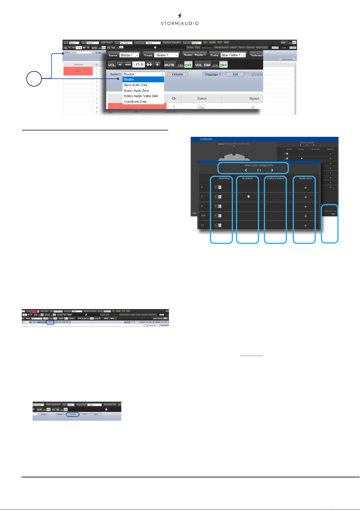
1. Create Theater
Select Theater in the drop down list and click
Create Theater to build your new theater.
Theater 1 will appear to the right of the Create
Theater button. Click Configure to proceed.
2. Configure the theater
When in the Theater Configurator, you will
be able to define each layer of the speaker
installation: base, height and top layers.
which speaker combination you expect
for the layer amongst predefined options
populated automatically depending on
the channels decoding capability of the
ISP version.
B. For each speaker, you can define whether
it is a full bandwidth or an active multiway
one, with up to 4 ways definable. At
this stage, only the number of ways is
requested: filters details will be defined
in the specific “Multi-way Loudspeaker
Setup” in page 18.
C. The Center channel can be turned to
Phantom mode, the signal being played
in Left and Right channels, removing the
need to have a physical center channel in
the installation.
D. Top channels can be defined as Dolby
Atmos Enabled for the case up-firing
speakers are used. In such case, select
the base speaker location which can be
either the “Front”, “Side” or ”Back” speakers
position, depending on the base layer
definition. Keep «None» for normal down-
1
A. Choose using the left and right arrows
B
A
C D E F

ISP Immersive Sound Processor
15
Configuration is shown. A four digits
description is given following this order:,
“Base Layer . LFE . Height Layer . Top Layer”.
H. It is possible to get a 3D view of the
Theater, toggling between 2D and 3D.
I. Save to exit and reach the Speakers
edition page loaded with the default
audio profile “New profile 1”.
Zones
Zones are mono or stereo, and with or without
a link to video output or can be dedicated
to headphone playback when used with an
external headphone amplifier. Stereo Audio/
Video and Headphone Zones include provisions
for adjusting lip sync. Audio only zones do not.
Zones occupy unused channels and can play
concurrently with a theater or without one. Note
that system wide, you can select one input for
the main theater (Main Source) and one Zone
1. Rename
You can rename a profile using Latin-1 table
characters. No special character allowed.
2. New
Click New to build a new fresh profile.
3. Duplicate
Build a variation of a saved profile. For
instance, you cannot edit Dirac reference
profiles directly although it can be useful to
tune levels of replicated speakers. In such
case, create a duplicate of the reference
profile and edit it to adjust the needed
parameters.
4. Save
After any changes to a profile are made or
creation of a new one, you must SAVE your
changes.
firing in ceilings speakers.
E. For each speaker, you can define whether
replication is required. Use this feature
for multiple subwoofers or multiple rows
of surround speakers declaration or any
speaker you wish to replicate. In case
there is no subwoofer in the system,
please select “0” in the subwoofer field.
F. Press Next to reach the next layer and
follow again steps A to E until all three
layers are defined.
G. At the end, a summary of the Speakers
GI1
2
34
2 input used by all the audio zones (Secondary
source). You can choose the Zone to play either
the Zone2 source or follow the Main Theater
source. Zones have all the same features of a
main theater except that channels are always
“Large”, they cannot include subwoofer channels,
and they are limited to mono or stereo. In order
to control a zone, it must be included in the
preset that is currently selected in the remote
control. See “Presets” on page 33for more details.
Profiles
For each Theater, Sub-Theater, and Zone, there is
a default profile created. You can save multiple
profiles for different listening preferences with
specific speakers settings (such as different EQ
profiles based on content type).
Profiles can be recalled as part of Presets (see
“Presets”, page 33). A profile includes: Speaker
definition (multi-way, levels, delays), bass
management, manual EQ, and Dirac filter design
if applied.
H

16
Individual Channel Adjustments
Once your theater is defined, each channel can
be individually adjusted. Child theater can also
be created, see page 24.
1. Channel Status
Each channel is enabled by default. If for
some reason this channel needs to be
disabled, click the ON button. It will turn to
OFF and audio will no longer be routed to
that channel. Note that audio will not be re-
routed to other channels. Channel status is
set per Theater / Zone and is not stored as
part of a profile.
2. Channel Type
When equiped with a Digital Output module,
each channel can be assigned to an Analog
or Digital output.
3. Channel EQ
Each channel can have up to 20 filters cells
configured selecting the wheel icon. Channel
EQ can be bypassed by selecting ON/OFF.
See “Channel EQ” on page 19for detailed EQ
options. EQ settings are stored as part of
profiles.
4. Signal
Indicates which signal is routed to this
output. Should you desire to remap signal
routing, you can do so with Output Mapping.
See “Output Mapping” on page 23 for details.
5. Channel Name
Name can be customized with up to 24
characters from Latin-1 table. No special
character allowed.
6. Delay units
Choose whether to measure channel delays
in meters (default), feet, or milliseconds.
7. Delay per Channel
Each channel should have distance/delay set
between that loudspeaker and the sweetspot.
You can define this in meters (default), feet,
or ms depending on your setting in point 6
above.
8. Level
Set the level of each channel in between
-100dB and +12dB in 1dB increments. Best
practice is to set other channels to a negative
figure relative to the loudest channel to avoid
clipping when possible. Global gain makeup
can be applied to the theater when the
relative level of the theater is too low (usually
a result of a high degree of correction due to
Dirac Live’s mixed phase filters). Use global
gain makeup judiciously to avoid clipping.
9. Limiter
To prevent distortion due to loudspeaker
overdriving or amplifier clipping, you may
wish to engage a limiter on a channel. When
enabled, a compressor will attenuate audio
above the threshold set by the Limiter Value
for that channel back down to that value.
For instance, if the limiter is enabled and
set to -3dBfs, any audio that exceeds -3dBfs
will be reproduced at -3dBfs. By their nature,
limiters are not ideal acoustic solutions, but
this feature can prevent subjectively worse
sounding distortion, or in extreme cases,
damage to loudspeakers or amplifiers. If you
find that you are aggressively using the limiter
12
13 14 15 16 18 19
2
1
3
4
9
8
6
11
17
7
5
10

ISP Immersive Sound Processor
17
function, you are encouraged to upgrade
loudspeakers and/or amplification.
10. Tilt EQ
For speakers behind a motorized screen for
example, you might need to change their
“audio brightness” depending on the screen
position up or down. TiltEQ allows the sound
to be darker or brighter.
11. Polarity
Check the box for any channel in which you
wish to invert signal polarity.
Test Tone Generator
The ISP includes a highly configurable test tone
generator which can be used to help manually
calibrate channels.
12. Generator
Click this button to turn on the tone generator.
It will automatically start with Group 1 with
green highlight on the active channels.
13. Setup
Unlike traditional generators, the ISP plays
tones per channel group. Click Setup to
define the groups and the channels they
contain. For example, if you have 2-way active
loudspeakers, you may wish to group the high
frequency and low frequency component of
each into one group.
14. Noise Selection
Choose the type of noise or tone created by
the generator.
• Sine: Generates a sine wave at the frequency
specified.
• Pink Noise: Generates full bandwidth pink noise.
• Pink Noise 400Hz-4kHz: Generates pink noise
band limited to one decade. This is particularly
useful when setting relative levels between
channels with dramatically different useful
bandwidths. Remember SPL meters measure not
only sound pressure but also bandwidth.
• External: it is possible to use an external noise
generator connected to one of the ISP input. This
is usually required when using an external tool
providing its own stimuli (Room EQ Wizard is one
of them, see “REW integration”, page 20).
15. Gain
The gain figure can be set so that the noise
generator operates at a level at or below that
of a normal source playing at 0dBFS. Default
is 0.1 (-20dBFS).
16. Group -/+
When the noise generator is active, use this
function to play the noise through different
groups defined in “13. Setup”.
17. Volume Reference
It is good practice when calibrating systems
to always work at a reference level such as
85dB C-weighted. Before activating the noise
generator, make sure the master volume is at
a low level. Set and recall a reference master
volume value. Click SET once you have dialed
the value you’d like to store. Click RECALL to
quickly return to that value.
18. RTA
When a USB microphone (such as the
optional Microphone Mini Kit) is connected
to the ISP, you can use the Real Time Analyzer
to visualize the response of loudspeaker
groups in the room. Note that the built in RTA
is not accurate enough to use for calibration,
but is useful for getting a good idea of
the approximate response of the system.
Maximum level of the capture can be set by
adjusting Mic Ref Level. Graph vertical scale
can be changed from Logarithmic (default) to
Linear.
19. DIRAC
See “Dirac Live” on page 25 for use of Dirac
Live® Calibration Tool.

18
Multi-way Loudspeaker Setup
During the initial Theater Definition setup, you
have the option of defining any speaker as
multi-way. Doing so will assign 2 to 4 output
channels to each speaker instead of 1. In this
configuration, more than 1 amplifier channel will
be used per loudspeaker, and the ISP will perform
the crossover function for each loudspeaker.
All settings detailed in section “Individual
Channel Adjustments” on page 16 also apply and
will not be covered again here. This section only
describes the differences notable for multi-way
loudspeaker configuration.
1. Channel Name
By default, the channel names are named by
the signal they receive. For clarity, you may
wish to rename these according to the signal
they reproduce e.g. Left Front High, Left Front
Mid, Left Front Low. Use Latin-1 character
table with no special character.
2. Signal
Note that in this example (Left Front is a
2-way active loudspeaker), Each of the first 2
channels receives the same Left Front signal.
3. Multi-way Management
Use this section to filter the signal for each
section.
• Section: Choose whether each channel
reproduces Full Range, Low Pass Filtered, Middle
(band pass), or High Pass Filtered audio. Two-way
speakers will not have Middle option.
• Crossover Frequency: When the section is
chosen as anything other than Full Range, set the
crossover frequency for the Low and High Pass
filters for each section.
• Slope: For each filter, select a slope. Options are
Butterworth (6dB / oct, 12dB / oct, 18dB / oct, 24dB
/ oct and 48dB / oct), Linkwitz Riley (12dB / oct,
24dB / oct, 36dB / oct and 48dB / oct).
4. Channel EQ
For each channel, you can adjust EQ by
selecting the Wheel. EQ can be bypassed
to compare with and without equalization
selecting On or Off.
5. Delay
Set the delay of each section. For active
multi-way loudspeakers, it may be helpful to
do this in milliseconds and measure time-
of-arrival differences at the crossover point
when using LR or BT6 filters to time align each
section of a multi-way loudspeaker.
6. Level
Active multi-way loudspeakers almost
certainly have different sensitivities per
module. Set the relative level of each here.
When possible, use 0 as the maximum
figure and attenuate other channels to
match the loudest channel. You can also set
global makeup gain for the entire theater as
described in “8. Level” on page 16.
Note that after making any changes, you must press the
SAVE button near the top right of the screen or you will loose
your changes.
1
6
5
2
3
4

ISP Immersive Sound Processor
19
1
2
6
7
8
3
4
5
Channel EQ
Each channel can have up to 20 filters cells for
equalization, including additional crossover
capabilities.
1. EQ Bypass
When developing a custom set of EQ per
channel, it is sometimes helpful to bypass
the entire group of EQ to check your progress
against the starting point.
2. Graphical UI
The EQs defined are visualised in a graphical
window. Individual and combined EQ
curves are shown, providing an instant
understanding of EQ impact on the
correction curve.
3. Create EQ
To design EQ curves for any channel, you
need to add EQ definition line using the
Create EQ button.
4. Filter Shape
Each filter must begin with a variation of one
of 5 types.
• Low Pass: Continuously declining output above a
cutoff frequency at a defined rate.
• High Pass: Continuously declining output below
a cutoff frequency at a defined rate.
• Bell: Band pass or cut filter with a defined center
frequency, boost or cut amount, and Q.
• Low Shelf: Boost or cut frequencies below a
cutoff frequency by a fixed amount.
• High Shelf: Boost or cut frequencies above a
cutoff frequency by a fixed amount.
For LPF and HPF choose a type and slope
amongst Butterworth (6dB / oct, 12dB / oct,
18dB / oct, 24dB / oct and 48dB / oct), Linkwitz
Riley (12dB / oct, 24dB / oct, 36dB / oct and
48dB / oct).
5. Delete
Unused EQ line can be removed using the Bin
button.
6. Status
In the course of designing your filter, you
may wish to measure or listen to progress
compared to the absence of that filter. Click
Active “No” to temporarily omit that filter from
the aggregate curve. Click “Yes” to activate it
back. You can also decide here whether it is
shown in the visualization curve by checking
the Graph item.
7. Quality Factor / Bandwidth
Bell filters require that you specify a Q. High
Q affects a narrow bandwidth, and low Q
affects a wide bandwidth. You can enter this
number directly in the text box or increment/
decrement by the amount chosen in the
header row using the +/- buttons to the right.
Or, click a fractional or multiple octave button
to automatically calculate Q.
8. Gain
Bell and shelving filters require that you set
the amount of boost or cut. You can enter this
number directly in the text box or increment/
decrement by the amount chosen in the
header row using the +/- buttons to the right.
9
10
11

20
1. REW import
The ISP offers the possibility to use external
Room Correction tool such as the Room
EQ Wizard (REW). REW offers very advanced
measurements and filtering capabilities
where you can define equalization and
measure the effect in both time and
frequency domain. This gives a total flexibility
for ISP users to go from a fully automated
approach with Dirac Live to a fully manual
approach that REW offers.
To allow for importing filters defined in the
REW tool, you must make sure that you
first set the REW tool for StormAudio ISP
compatibility and select “Export filter settings
as Texts” in the tool.
Once done, you can then do your EQ for each
channel and export the equalization as a
“*.txt” file.
In the ISP, select “REW Import” and load the
file corresponding to the selected channel.
You will prompted for choosing between
adding to or replacing existing EQs. Once
selected, the EQ page will then be loaded
with the REW defined filters.
Note that you can define up to 12x Parametric EQ and 2x
High Pass or Low Pass filters (up to 48dB slope) in the REW
tool with the StormAudio compatibility mode.
1
9. Frequency
Each filter requires that a center or cutoff
frequency be specified. You can enter this
number directly in the text box or increment/
decrement by the amount chosen in the
header row using the +/- buttons to the right.
10. Channel Select
Select the desired channel to equalize here.
11. Copy to Channel
You may wish to duplicate your filter set to
another channel without manually rebuilding
it for each identical channel. Select one or
more channel(s) to copy the current filters to
and click COPY.
Note that after making any changes, you must press the
SAVE button near the top right of the screen or you will loose
your changes.
Room EQ Wizard integration
Other manuals for ISP CORE 16
1
This manual suits for next models
1
Table of contents
Other Storm Audio Recording Equipment manuals


