Spectra Precision GL412N User manual

1

TABLE OF CONTENTS
Introduction
For Your Safety
Components
How to Use the Laser System
Powering the Laser
Turning On/Off the Laser
Turning On/Off the Radio Remote Control
Pairing the remote control and the HL760 receiver with the transmitter
Laser Setup
Standard Features
Manual Mode
Mask mode
Activating/Deactivating Standby Mode
Line Scan - Vertical Setup
MENU Features
Y-X-Grade Entering
Selecting Rotation Speed
Automatic Grade Match
Automatic PlaneLok mode
Mask Mode
Temperature Check
Setting Menu
Info
Service menu
Line Scan (Vertical Setup)
2

Setting menu details
HI-alert selection
Grade Entry
Grade Display
Sensitivity
Language
Radio Channel
CALIBRATION
Checking Calibration of the Y- and X-Axes
Checking Calibration of the Z-(vertical) Axis
PROTECTING THE UNIT
CLEANING AND MAINTENANCE
PROTECTING THE ENVIRONMENT
WARRANTY
TECHNICAL DATA
3

Introduction
Thank you for choosing one of the Spectra Precision Lasers from the Trimble family of precision lasers.
The grade laser is an easy-to-use tool that offers accurate horizontal, vertical and sloped laser reference up
to 1300 ft (400 m) away using a receiver.
For Your Safety
For hazardless and safe operation, read all the user guide instructions.
-Use of this product by people other than those trained on this product may result in exposure to
hazardous laser light.
- Do not remove warning labels from the unit.
- The GL422N/GL412N is a class 2 laser (<3,4mW) IEC 60825-1:2014)
-Never look into the laser beam or direct it to the eyes of other people.
- Always operate the unit in a way that prevents the beam from getting into people's eyes.
-If initial service is required, which results in the removal of the outer protective cover, removal
must only be performed by factory-trained personnel.
Caution: Use of other than the described user and calibration tools or other procedures
may result in exposure to hazardous laser light.
Caution: Using different than described at the GL422N/GL412N user guide, may result in
unsafe operation.
4

GL4X2N - Components
5
a
b
c
e
d
g
j
i
h
f
q
r
s
r
s
k
l
m
n
o
p

Components
a Power Button
b Battery LED
c Manual/Standby Button
d Leveling LED
e Manual/HI-Warning LED
f Up and Down Arrow Buttons
g Left and Right arrow Buttons
h M –button
iE - button
j Liquid Crystal Display (LCD)
k Rotor
6
l Sunshade
m Sighting Guides
n Axes-Alignment-Marks
o Recharge Jack
p Handle
q Battery door
r 5/8x 11 Tripod Mounts
s Rubber feet
How to Use the Laser System
Powering the Laser
Batteries
WARNING
Ni-MH batteries may contain small amounts of harmful substances.
Be sure to charge the battery before using it for the first time, and after not using it for an extended length of
time.
Charge only with specified chargers according to device manufacturer‘s instructions.
Do not open the battery, dispose of in fire or short circuit; it may ignite, explode, leak or get hot causing
personal injury.
Dispose in accordance with all applicable federal, state, and local regulations.
Keep the battery away from children. If swallowed, do not induce vomiting. Seek medical attention
immediately.

Installing Batteries
Remove the battery door by turning the center screw 90°counterclockwise. Insert batteries (or a
rechargeable battery pack) into the housing so that the negative poles are on the bigger battery spiral
springs.
DO NOT REMOVE RECHARGEABLE BATTERIES FROM THEIR HOLDER AND INSTALL ALKALINE
BATTERIES, SEVERE DAMAGE TO UNIT WILL RESULT IF CHARGING IS ATTEMPTED.
Install the battery door and tighten it by turning the center screw 90°clockwise.
A mechanical switch prevents alkaline batteries from being charged. Only the original rechargeable battery
pack allows charging within the unit. Any other rechargeable batteries have to be charged externally. 7
Powering the GL
1 –GL is shipped with a rechargeable
NiMH battery pack, it is keyed to prevent
mis-insertion.
2 –The rechargeable battery pack can be
charged inside of the unit
3 –Alkaline batteries can be used as a
backup
4 –Plus and minus symbols at the battery
door indicate how to put the alkalines
into the battery compartment

Recharging the Batteries
The laser is shipped with a rechargeable NiMH-battery pack.
Note: The battery LED shows the approximate charge of the batteries.
The LED will flash when battery voltage is between 3.8 and 4.0 volts.
The LED will be on continuously when battery voltage is less than 3.8 volts.
The charger requires approx. 13 hours to charge empty rechargeable batteries.
For charging, connect the plug of the charger to the recharge jack of the unit.
New or long-time out-of-use rechargeable batteries reach their best performance after being charged and
recharged five times. For Indoor applications the charger can be used as a power supply for the GL.
Alkaline batteries can be used as a backup. Insert 4 D-cell batteries noting the plus (+) and minus (-)
diagrams at the battery door.
The batteries should only be charged when the laser is between 50°F and 104°F (10°C
to 40°C). Charging at a higher temperature may damage the batteries. Charging at a
lower temperature may increase the charge time and decrease the charge capacity,
resulting in loss of performance and shortened life expectancy.
8

RC402N Radio Remote Control
Powering the RC402N
1. Open the battery door using a coin or similar pry
device to release the battery door tab on the RC402N.
RC402N will be shipped with alkaline batteries
Rechargeable batteries can be used optional but need
to be charged externally
2. Insert twoAA batteries noting the plus (+) and minus (-)
diagrams inside the battery housing.
3. Close the battery door. Push down until it “clicks”
into the locked position.
Turning On/Off the Radio Remote Control
The radio remote control is a hand-held device that allows you to send operational commands to the
laser from a remote location.
Press the power button to turn on the radio remote control.
Note: When the remote control is initially turned on, the standard display (model number and software
version) appear for the first 3 seconds, then the RC402N LCD shows the information as shown at the
laser.
With every button press, the LCD backlight is activated and turns off automatically if no button is
pressed for 8 seconds.
To turn off the radio remote control, press and hold the power button for 2 seconds.
If the RC402N is outside of the operating range or not paired with the transmitter,
the LCD shows the model number and software version.
Note: 5 minutes after the last button press, the remote control turns off automatically.
9

Pairing the remote control with the transmitter
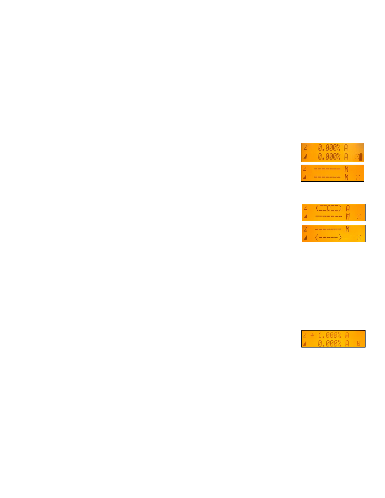
First, make sure the transmitter and the remote control are turned off. Then press and hold the Manual
button and turn on the transmitter. During the next 6 seconds repeat the same steps on the remote control.
The transmitter’s displays show the following information:
The transmitter and remote’s display show Pairing OK for one second and then the
same information as shown at the laser’s LCD to indicate the transmitter has been
matched with the remote control.
To pair the HL760 receiver with the transmitter
Make sure the transmitter is turned off.
First, turn on the receiver, then press and hold the Deadband (A) and Audio (B) buttons for two seconds.
After two seconds, the display shows MENU first, then RDIO
Press and release the Enter button –display shows the current radio mode.
If not already set to LS, press Units (C) button (current mode flashes)
and then press Deadband (A) or Audio button (B) until LS is displayed.
Press Units (C) button again to enter selection.
Press and release the Audio (B) button –display shows PAIR.
Press the Units (C) button again –the display shows PAIR and a rotating bar.
Then press and hold the Manual button and turn on the transmitter
(Battery LED flashes fast).After completing PAIR, OK will be displayed.
The laser pairs now automatically with the new receiver and turns back to the standard function.
Press and release the HL760 Power button two times to exit the menu at the receiver.
A laser symbol and an antenna is lit to confirm the receiver is ready for communication
with the laser. 10
or or
A
B
C

Fingerprint function at the HL760 receiver
Fingerprinting makes sure the HL760 detects only the laser beam of the paired tarnsmitter.
Laser fingerprinting is automatically activated and confirmed with a clock symbol after a HL760 has been
paired with the laser. To recognize an ignore laser strikes from other than the paired transmitter takes
typically 5 seconds; sometimes few seconds more.
Laser Setup
Position the laser horizontally (tripod mount and rubber feet downward!) on a stable platform, wall mount or
tripod at the desired elevation.
The laser recognizes automatically whether it is used horizontally or vertically when switched on.
Turning On/Off the laser
Press the power button to turn On/Off the laser.
The LCD shows Initialisation and then for one second the model number and Software Rev.
The LEDs (b, dand e) are turned on for 2 seconds.At the LCD, the last used grade values, the mask mode
and battery status will be displayed. The battery symbol disappears after few seconds and comes back if
the batteries are getting low.
If a grade value has been dialed in, the unit starts the temperature/reference check while the thermometer
symbols are flashing.
When the temperature/reference check has been finished, the standard display appears and the Asymbols
flash until self-leveling has been completed.
Pressing and holding the E button shows the actual rotation speed and the internal temperature.
11
GL412N - horizontal setup - GL422N GL412N - vertical setup - GL422N

Features and Functions
Standard Display
The remote control mirrors the functionality of the laser keypad
M-Button: Quickly press and release starts
the MENU entry and can be used to return
to the previous menu position
E-Button: Quickly press and release starts
the selected mode
Manual Button: Quickly press and release
activates/deactivates the manual mode
Up/Down Arrow Buttons
Left/Right Arrow Buttons
ON/OFF button - press for 1 second to turn
on the unit; press and hold for 2 seconds to
turn off the unit
Battery- LED (red)
Leveling- LED (green)
Manual/HI-Warning- LED (red)
12
Battery status laser HI alert function
Mask mode indication is activated
13
Standard Features
Manual mode
Pressing and releasing Manual button activates/deactivates the manual mode
regardless if set up horizontal or vertical.
Manual mode is indicated by horizontal lines next to the axes symbols and a M.
In Manual mode (horizontal), the Y-axis can be sloped by pressing the Up-and Down-
Arrow buttons on the laser‘s keypad or the remote control. Additionally, the X-axis can
be sloped by pressing the Left-and Right-Arrow buttons on the laser or remote control.
In vertical mode, the Up and Down arrow buttons adjust the vertical slope, and the Left
and Right arrow buttons align the laser reference to the right/left side.
To resume automatic self-leveling mode, press the Manual button again.
Mask Mode
Mask Mode –allows you to electronically turn off the laser beam (electronic shutters) in up to 3 lighthouse
windows to prevent interference with other receivers on the jobsite. Mask Mode can be selected as a standard
feature as well as using the menu.
To activate the mask mode on the + or -Y-axis, press the Up or Down arrow button at the laser or remote
control, then within <1 second press and release the Manual button.
Press the Right or Left arrow button in sequence with the Manual button to activate/deactivate the mask mode
for the + or –X axis
The display indicates which side of the laser the beam has been electronically turned off.
Note: The unit always powers up with the mask mode deactivated (default).

14
Activating/Deactivating Standby mode
Press and hold the Manual button at the laser or remote control for 3 seconds activates the Standby mode.
The self-leveling will be stopped and the beam will be turned off while the HI alert is still active.
The display shows Standby and the HI/MAN-LED flashes red every 5 seconds.
To deactivate Standby mode and restore full operation of the laser, press and hold the
Manual button at the laser or remote control again for 3 seconds.
Line Scan - Vertical Setup
When setting up the unit vertical, Line Scan centers the rotor horizontally and can be used to align the laser
reference to a desired line position. Line Scan can be activated as a standard feature as well as using the menu.
Pressing and releasing the Left/Right buttons simultaneously starts Line Scan while the rotor checks
the limits of the X- axis (all laser LEDs are turned off) and stops at the center position.
Pressing the Manual button stops the movement and changes the unit into manual mode.
Corrections left and right can be done using Left/Right arrow buttons.
Press and release the Manual button to change the unit back to full automatic mode.

15
Menu Functions
Press and release M button at the Standard Display to enter the MENU.
The menu offers always only the features which can be selected depending on the setup
(horizontal or vertical).
The actual available function will be marked in arrow brackets >> <<.
A down arrow at the the right site indicates that the user can scroll down through the menu using the down
arrow button.
After going to the next menu row, an up/down arrow at the the right site indicates that the user can scroll
up/down through the menu using the Up/Down arrows buttons.
Pressing and releasing button M changes the unit always back to the standard or previous display.
Press and release the Up/Down buttons until the desired function at the selected menu row is marked.
Press and release button E to open the submenu OR start the selected function.
Menu functions when set up horizontal (GL4X2N)
Menu functions when set up vertical (GL4X2N)

Y-X-grade entering
Step and Go mode
Quickly press and release button Mopens the menu.
>>Grade<< will be shown.
Press/release button EBoth grade values will be shown.
Press/release Mbutton escape/return to the standard display.
Press and hold button Left or Right to change X- axis grade value (only
GL422N) after the comma; press and hold buttons Left + Right
simultaneously starts X-axis quick change mode where the grade value in
front of the comma will be set to 0% and then starts changing in 1%
increments.
Press and hold button Up or Down for changing Y -axis grade value; press
and hold buttons Up + Down simultaneously starts Y- axis quick change
mode where the grade value in front of the comma will be set to 0% and then
starts changing in 1% increments.
Note: An asterisk at the right side indicates which grade value will be
changed. The speed of the grade value change increases with the amount of
time the button is held down.
Note: The grade value for both axes increases in 1.00% increments. When
the grade value for either axis reaches its highest amount, the grade value
switches to the lowest value for that axis. For example, the value switches
from +15% to -10%.
The laser will self-level to the required grade position after confirming the
grade change with button E.
Note: The Asymbols at the LCDs will flash until the laser has been self-
leveled to the requested grade position. 16

Y-X-grade entering
Digit Select mode (Default)
Quickly press and release button M opens the menu.
>>Grade<< will be shown.
Press/release button EBoth grade values will be shown and a cursor
flashes at the +Y sign.
Press/release Mbutton escape/return to the standard display.
Pressing and releasing Right or Left button moves the cursor to the
right/left and in a circle to the next row.
Use Down or Up button to change the sign (grade reverse) and set the
desired digit.
For a quick cursor toggle between the X-(only GL422N) and Y-axis, press
and release Manual button.
Press and hold the Manual button for 2 seconds sets the grade to 0%.
Quickly press and release button Eto confirm the selected grade value and
return to the standard display. The laser will self-level to the required grade
position.
Note: The Asymbols at the LCD’s will flash until the laser has been self-
leveled to the requested grade position.
17

18
Selecting the Rotation speed
Quickly press and release button M opens the menu.
Repeatedly press the down arrow button until >>Rotation<< will be marked.
Press/release button EBoth rotation values will be shown.
Repeatedly pressing buttons Up/Down toggles between 300 and 600 rpm (Default)
regardless if the unit is in automatic or manual mode.
Quickly press and release button Eto confirm the selected rotation speed.
Automatic Grade Match
The Grade Match mode can be activated in horizontal automatic mode.
In Grade Match mode, the laser can be used to measure the existing grade value between two known elevation
points (up to 100 m (330 ft) located on the Y-axis of the laser.
1. Set up the laser over the reference point.
2. Attach the HL760 receiver to a grade rod. Check the laser’s elevation next to
the laser then position the receiver at the second point WITHOUT changing the
receiver’s elevation on the rod.
3. Use the sighting guides on the top of the laser to align the laser to the receiver.
Turn the laser on the tripod until it is roughly aligned to the receiver’s position
4. Press and release the Mbutton at the Standard Display and select >>Grade Match<<.
5. Press and release the E button to open the Grade Match submenu; select the Y-axis
then press the Ebutton to start Grade Match.
Note: The laser starts to search for the receiver. The HL760 display shows a flashing –GM–
during the time the laser is searching and adjusting the beam to the on-grade position.
When Grade Match has been completed, the HL760 goes back to the standard elevation
display. The remote control as well as the laser will display the final measured grade value.
Exiting of Grade Match can be done by pressing the Manual button where the unit goes
always back to automatic mode.

Automatic PlaneLok mode
The PlaneLok mode can be activated in horizontal automatic and vertical automatic
and manual mode. In PlaneLok mode when set up horizontal, the beam will be
locked to a fixed elevation point (up to 100 m (330 ft) located on the
Y-axis of the laser. For keeping vertical alignments fixed to the direction or
slope positions, PlaneLok can be used on the Z- (only GL422N) or X-axis.
1. Set up the laser over the reference point.
2. Attach the HL760 receiver to a grade rod. Place the receiver at the second point and adjust it to the On-grade
position. The receiver should be permanently mounted at this location and at the desired elevation.
3. Use the sighting guides on the top of the laser to align the laser to the receiver. Turn the laser on the tripod
until it is roughly aligned to the receiver’s position.
4. Press and release the Mbutton at the Standard Display and select >>PlaneLok<<.
5. Press and release button E to open the PlaneLok submenu; select the Y-axis when set up horizontally or the
X-axis when set up vertically; then press the E button to start PlaneLok.
Note: The laser starts to search for the receiver. The HL760 display shows a flashing –PL–
during the time the laser is searching and adjusting the beam to the on-grade position.
When PlaneLok is complete, –PL–stops flashing at the HL760 and RC402N display.
When setting up the transmitter vertical, PlaneLok can be used at the Z- or X-axis.
1. Press and release the Mbutton at the Standard Display and select >>PlaneLok<<.
2. Press and release button E to open the PlaneLok submenu; select the Z-axis
(only GL422N) or the X-axis; then press button Eto start PlaneLok.
Note: When used in vertical mode, the receiver has to be placed with the
photocell on the bottom side;for Z-PlaneLok , align the top of the receiver
to the top of the laser. For getting the best performance and a longer
operating range set up the HL760 at least 0.5 m (2 ft) above the ground.
Note: In every PlaneLok mode the laser continues to servo to the receiver’s signals.
Any loss of signal over an extended period of time (1 minute) causes the laser to go
into the HI-alert condition (beam turns off, rotor stops and a warning message occurs
at the LCD). PlaneLok mode can be reactivated after the Error message has been
deleted with the Ebutton.
Exiting of PlaneLok can be done by pressing Manual button or any HL760 button. 19

Mask mode
Press and release the Mbutton at the Standard Display and select >>Mask Mode<<.
Depending on which side the beam should be turned off, the required side can
be selected. Press and release the Ebutton, the mask symbol occurs.
For selecting the side, press and release one of the arrow buttons.
When all areas have been set, press button E to store the mask sector selection
until the unit will be turned off.
Note: The unit always powers up with the mask mode deactivated (default).
Start Temperature (Reference) Check
Before starting some grade work which is very sensitive an additional Reference Check can be started
manually. Press and release the Mbutton at the Standard Display and select >>Temp Check<<.
Pressing and releasing the E button starts the Reference Check considering the
current temperature inside the housing.
While the rotor checks the correct position the rotation will be stopped.
Setting Menu
Please see the Setting Menu details at the following pages.
20
This manual suits for next models
1
Table of contents
Other Spectra Precision Laser Level manuals

Spectra Precision
Spectra Precision LL300S User manual

Spectra Precision
Spectra Precision Trimble UL 633N Installation guide

Spectra Precision
Spectra Precision HV302 User manual

Spectra Precision
Spectra Precision 1452GC User manual

Spectra Precision
Spectra Precision LL300S Instruction manual

Spectra Precision
Spectra Precision LL100N Assembly instructions

Spectra Precision
Spectra Precision HV302 User manual

Spectra Precision
Spectra Precision AL28M User manual

Spectra Precision
Spectra Precision DET-2 User manual

Spectra Precision
Spectra Precision LL300 User manual


