Spectra Precision Trimble UL 633N User manual

GL400 Series
www.trimble.com
Trimble Construction Division
5475 Kellenburger Road
Dayton, Ohio 45424
USA
+1-937-245-5600 Phone
www.trimble.com
User Guide
Bedienungsanleitung
Manuel de l´utilisateur
Guida per l´uso
Gúia del usuario
Gebruikershandleiding
Operatörshandbok
Brugermanual
Guia do Usuário
Bruksanvisning
Käyttäjän opas
取扱説明書
© 2007, Trimble Navigation Limited. All rights reserved.
UL 633N
GL400 Series
www.trimble.com
Trimble Construction Division
5475 Kellenburger Road
Dayton, Ohio 45424
USA
+1-937-245-5600 Phone
www.trimble.com
User Guide
Bedienungsanleitung
Manuel de l´utilisateur
Guida per l´uso
Gúia del usuario
Gebruikershandleiding
Operatörshandbok
Brugermanual
Guia do Usuário
Bruksanvisning
Käyttäjän opas
取扱説明書
© 2007, Trimble Navigation Limited. All rights reserved.
Руководство пользователя
Russ_Titel.indd 1 06.05.2008 08:38:53
© 2017 , Trimble Inc.. All rights reserved.
PN 112644-00 Rev. B (07/17)
Trimble - Spectra Precision Division
5475 Kellenburger Road
Dayton, Ohio 45424 U.S.A.
+1-937-245-5600 Phone
Instrukcja obsługi
UL 633N

112644-00 Rev. B (07/17)
df
h
g
i
k
i
c
e
b
a
j
l
Service and Customer Advice
North America
Trimble - Spectra Precision Division
5475 Kellenburger Road
Dayton, Ohio 45424 U.S.A.
888-527-3771 (Toll Free)
+1-937-245-5600 Phone
+1-937-482-0030 Fax
www.trimble.com
www.spectralasers.com
www.spectraprecision.com
Europe
Trimble Kaiserslautern GmbH
Am Sportplatz 5
67661 Kaiserslautern
GERMANY
+49-6301-711414 Phone
+49-6301-32213 Fax
Latin America
Trimble Navigation Limited
6505 Blue Lagoon Drive
Suite 120
Miami, FL 33126
U.S.A.
+1-305-263-9033 Phone
+1-305-263-8975 Fax
Africa & Middle East
Trimble Export Middle-East
P.O. Box 17760
Jebel Ali Free Zone, Dubai
UAE
+971-4-881-3005 Phone
+971-4-881-3007 Fax
Asia-Pacic
Trimble Navigation
Australia PTY Limited
Level 1/120 Wickham Street
Fortitude Valley, QLD 4006
AUSTRALIA
+61-7-3216-0044 Phone
+61-7-3216-0088 Fax
China
Trimble Beijing
Room 2805-07, Tengda Plaza,
No. 168 Xiwai Street
Haidian District
Beijing, China 100044
+86 10 8857 7575 Phone
+86 10 8857 7161 Fax
www.trimble.com.cn

1
TABLE OF CONTENTS
1 INTRODUCTION 3
2 FOR YOUR SAFETY 3
3 COMPONENTS 3
4 HOW TO USE THE LASER SYSTEM 4
4.1 Powering the Laser 4
4.1.1 Batteries 4
4.1.2 Recharging the batteries 4
4.2 RC603N Radio/IR Remote Control 4
4.2.1 Powering the RC603N 4
4.2.2 Turning On/Off the RC603N 4
4.3 ST802/ST805 Signal Transporter 5
4.3.1 Powering the ST802/ST805 5
4.3.2 Turning On/Off the ST802/ST805 5
5 LASER SETUP 5
5.1 Turning On/Off the Laser 5
5.2 Features and functions 6
5.2.1 Standard Display 6
5.3 Standard Features 6
5.3.1 X-Y-Z-grade entering - Digit Select mode (Default) 6
5.3.2 X-Y-Z-grade - Step and Go mode 7
5.3.3 Rotation Mode 7
5.3.4 Pointing Mode 7
5.3.5 Scan Mode 8
5.3.6 Manual Mode 8
6 SPECIAL MENU FEATURES 8
6.1 Menu Functions (radio controlled) 8
6.2 Menu Functions (IR controlled) 8
6.3 Automatic PlaneLok Mode 9
6.4 Automatic Grade Match 10
6.5 Manual Grade Match 11
6.6 Automatic Axis Alignment 11
6.6.1 Automatic Axis Alignment 11
6.6.2 View Align Angles 12
6.6.3 Edit Align Angles 12
6.7 Mask Mode 12
6.8 Spot Search 12
6.9 Activating/Deactivating Standby mode 13
6.10 Start Reference Check 13
GB

2
6.11 Setting Menu 13
6.12 Info 13
6.13 Service 14
6.14 RC603N Service Menu 14
6.14.1 RF IR Options 14
6.14.2 RF Connectivity 14
7 SPECIAL FEATURES - VERTICAL SETUP 15
7.1 Z-Axis Automatic Spot Align 15
7.2 Z-axis Automatic Spot Lok 15
7.3 Z-axis Automatic Spot Match 16
7.4 Line Scan 16
7.5 Beam Plunge 16
8 SETTING 17
8.1 Pairing 17
8.2 Pairing the laser with remote control 17
8.3 Pairing the laser with receiver HL760 17
8.4 Pairing the laser with the Signal Transporter (ST802/ST805) 18
8.5 Grade Entry 18
8.6 Grade Display 18
8.7 Sensitivity Selection 19
8.8 HI-alert selection 19
8.9 User Name 19
8.10 Set Password 19
8.11 Password On/Off 20
8.12 Radio (RF-Channel) 20
8.13 Select Language 20
8.14 Position Info 20
9 CALIBRATION 21
9.1 Checking Calibration of the Y- and X-Axes 21
9.2 Checking Calibration of the Z-(vertical) Axis 21
10 TROUBLESHOOTING 22
11 SF601 SPOT FINDER USER GUIDE 23
12 PROTECTING THE UNIT 26
13 CLEANING AND MAINTENANCE 26
14 PROTECTING THE ENVIRONMENT 26
15 WARRANTY 26
16 TECHNICAL DATA 27
16.1 UL633N 27
16.2 RC603N 27
16.3 SF601 27
17 DECLARATION OF CONFORMATY 27
18 ELECTROMAGNETICAL COMPATIBILITY 28

3
1 INTRODUCTION
Thank you for choosing one of the Spectra Precision Lasers from the Trimble family of precision lasers.
The universal laser is an easy-to-use tool that offers accurate horizontal, vertical and sloped laser reference
up to 1300 ft (400 m) away using a receiver. The plumb beam can be detected automatically and manually
using the additional SpotFinder.
2 FOR YOUR SAFETY
For hazardless and safe operation, read all the user guide instructions.
• Useofthisproductbypeopleotherthanthosetrainedonthisproductmayresultinexposuretohazardous
laser light.
• Donotremovewarninglabelsfromtheunit.
• TheUL633NisClass3A/3R(IEC60825-1:2014).
• Neverlookintothelaserbeamordirectittotheeyesofotherpeople.
• Alwaysoperatetheunitinawaythatpreventsthebeamfromgettingintopeople‘seyes.
• Ifinitialserviceisrequired,whichresultsintheremovaloftheouterprotectivecover,removalmustonlybe
performed by factory-trained personnel.
Caution:Useofotherthanthedescribeduserandcalibrationtoolsorotherproceduresmayresult
inexposuretohazardouslaserlight.
Caution:UsingdifferentthandescribedattheUL633Nuserguide,mayresultinunsafeoperation.
3 COMPONENTS
a Keypad/LCD-Display
b Handle
c Rotor with fan beam lens
d Sunshade
e Axes-Alignment-Marks
f Sighting Guides/Scope Mounts
g Battery door
h Rubber Cover/Recharge Jack
i 5/8” x 11 Tripod Mounts
j Rubber Feet
k Turnable Legs
l Plus and Minus Battery Diagrams

4
4 HOW TO USE THE LASER SYSTEM
4.1 POWERING THE LASER
4.1.1 Batteries
WARNING
Ni-MHbatteriesmaycontainsmallamountsofharmfulsubstances.Besuretochargethebatterybeforeusing
itforthersttime,andafternotusingitforanextendedlengthoftime.Chargeonlywithspeciedchargers
accordingtodevicemanufacturer‘sinstructions.Donotopenthebattery,disposeofinreorshortcircuit;it
mayignite,explode,leakorgethotcausingpersonalinjury.Disposeinaccordancewithallapplicablefederal,
state,andlocalregulations.Keepthebatteryawayfromchildren.Ifswallowed,donotinducevomiting.Seek
medical attention immediately
4.1.2 Recharging the Batteries
ThelasermightbeshippedwitharechargeableNi-MHbatterypack.
Note: TheapproximatechargeofthebatteriesisshownatthelefttopsideoftheLCD.
Thechargerrequiresapprox.10hourstochargeemptyrechargeablebatteries.
Forcharging,connecttheplugofthechargertotherechargejackofthebatterypack.
Neworlong-timeout-of-userechargeablebatteriesreachtheirbestperformance
afterbeingchargedandrechargedvetimes.ForIndoorapplicationsthecharger
can be used as a power supply for the laser.
Alkalinebatteriescanbeusedasabackup.Insert4D-cellbatteriesnotingtheplus(+)andminus(-)diagrams
inside the battery housing.
The batteries should only be charged when the laser is between 50° F and 104° F (10°C to
40°C). Charging at a higher temperature may damage the batteries. Charging at a lower
temperature may increase the charge time and decrease the charge capacity, resulting in
loss of performance and shortened life expectancy.
4.2 RC603N Radio/IR Remote Control
4.2.1 Powering the RC603N
1. Open the battery door using a coin or similar pry device to release
thebatterydoortab onthe RC603N.RC603N willbe shippedwith
alkalinebatteries.Rechargeablebatteriescanbeusedoptionalbut
needtobechargedexternally
2.InserttwoAAbatteriesnotingtheplus(+)andminus(-)diagrams
inside the battery housing.
3.Close the battery door. Push down until it “clicks” into the locked
position.
4.2.2 Turning On/Off the RC603N
Theradio/IRremotecontrolisahand-helddevicethatallowsyoutosendoperationalcommandstothelaser
from a remote location.
Pressthepowerbuttontoturnontheradioremotecontrol.Thesymbol“ ”andadditionalverticalbarsappear
in the right corner of the remote’s top display line indicating the radio connection status between the laser and
theremotecontrol.IftheRC603Nisoutsidetheradiooperatingrangetheremoteswitchesautomaticallyinto
theIRconnectioncapability.
Note:Whentheremotecontrolisinitiallyturnedon,thestandarddisplay(modelnumberandsoftwareversion)
appearfortherst3seconds,thentheaxessymbolsandlast-enteredgradeforeachaxisappearintheLCD.
Witheverybuttonpress,theLCDbacklightisactivatedandturnsoffautomaticallyifnobuttonispressedfor
8seconds.
To turn off the radio remote control, press the power button for two secounds.
Note:5minutesafterthelastbuttonpress,theremotecontrolturnsoffautomatically.

5
4.3 ST802/ST805 SIGNAL TRANSPORTER
4.3.1 POWERING THE ST802/ST805
1.Open the battery door using a coin or similar pry device to release the battery door tab on the
ST802/ST805.ST802/ST805willbeshippedwithalkalinebatteries.Rechargeablebatteriescan
beusedoptionalbutneedtobechargedexternally.
2.InserttwoAAbatteriesnotingtheplus(+)andminus(-)diagramsinsidethebatteryhousing.
3.Closethebatterydoor.Pushdownuntilit“clicks”intothelockedposition.
4.3.2 Turning On/Off the ST802/ST805
Thesignaltransporter(ST)isahand-helddevicethatextendstheradiorangeofalaserwhichispairedwith
theST.Pressthepowerbuttontopoweronthesignaltransporter.AllLEDsturnonforthreeseconds.Finally
aashingyellowstatusLEDshowsthesignaltransporterhasbeenpairedwithalaserbutthislaserisnot
available.AsolidblinkingyellowstatusLEDisshowingthattheradioconnectionbetweenthesignaltransporter
and the paired laser has been established.
5 LASER SETUP
Position the laser horizontally (tripod mount and rubber feet downward!) on a stable platform, wall mount or
tripod at the desired elevation.
The laser recognizes automatically whether it is used horizontally or vertically when switched on.
5.1 Turning On/Off the laser
Press the power button for one second to turn On the laser.
Press the power button for two seconds to turn Off the laser.
Note:Whenagradevaluehasbeenenteredandaftertemperaturechangeofmorethan9°F(5°C),theunit
startsthetemperature/referencecheckwhilethethermometersymbolisashing(Pic1).
Anothertemperaturechecktakesplaceafter20min.andnallyevery60min.Whenthetemperature/reference
checkhasbeennished,thestandarddisplayappearsandthebubblesymbolsashuntilself-levelinghas
beencompleted(Pic2).
Iftheself-levelingcan’tbenishedbasedontheselectedsensitivity,anerrormessageappears.
AbubblesymbolhelpstoadjusttheunitatthecrossaxiswhensetupverticalforautomaticSpotAlignorin
vertical manual mode.
Pic 1 Reference check Pic 2 Standard display horizontal
Pic 3 Standard display vertical

6
5.2 Features and Functions
5.2.1 Standard Display
The remote control mirrors the functionality of the laser keypad
Button 1: Quicklypressandreleasestartsthe
MENU entry.
Button 2: Quicklypressandreleasestartsthe
grade entering mode.
Button 3: Quicklypressandreleaseactivates/
deactivates the manual mode.
Button 4: Quicklypressandreleasetotoggle
through the pre-selected rotation speeds.
Press and hold for three seconds
changestheunitintoscanmode.When
inscanmode,quicklypressandrelease
button 4 toggles through the pre-selected
scan sizes.
Button 5, 8:up/downarrowbuttons.
Button 6, 7:left/rightarrowbuttons.
Button 9: ON/OFFbutton-pressfor1secondto
turnontheunit;pressandholdfor2
seconds to turn off the unit.
Leveling/Standby – LED (green/red)
Batterystatuslaser HIalertfunctionisactivated
Maskselection BatteryStatusRemoteControl
StatusRadioConnectivity
Rotationspeed/Scanangle
FanBeamisactivated
5.3 Standard Features
5.3.1 X-Y-Z-grade entering – Digit Select mode (Default)
Quicklypressandreleasebutton2 (Pic5)startsthegradeenteringmode.
Bothgradevalueswillbeshown.
Acursor(Pic6)blinksatthecurrentpositionwhichcanbechanged.
Press/releasebutton1aquicksetto0%
Press/releasebutton2achange the sign in front of the grade value
Press/releasebutton3areturn to the standard display.
Quicklypressandreleasebutton4toconrmtheselectedgradevalueandreturntothestandarddisplay.
Press and release button 5or 8(downorup)tomovethecursortotheX-orY-axis(notusedinZ-mode).
Pressing and releasing button 6or 7(rightorleft)movesthecursortotheright/left.
Usebutton 1 or 2(PlusorMinus)tosetthedesireddigit(Pic9).
Thelaserwillself-leveltotherequiredgradepositionafterconrmingthegradechangewithbutton4.
Pic 5 Standard Display Pic 6 Grade Entry Mode

7
Note: ThebubblesymbolsatthelaserandremotecontrolLCDwillashuntilthelaserhasbeenself-leveled
totherequestedgradeposition.
5.3.2 X-Y-Z-grade entering – Step and Go mode
Howtochangeto‚StepandGo‘modeseechapter8.5
Quicklypressandreleasebutton2(Pic10)startsthegradeenteringmode.Bothgradevalueswillbeshown.
Press/releasebutton1agrade reverse Y (Pic 11)
Press/releasebutton2agrade reverse X (Pic 11)
Press/releasebutton3areturn to the standard display
Quicklypressandreleasebutton4toconrmtheselectedgradevalueand
return to the standard display
Press and hold button 6or 7(left/right)tochangeX-axisgradevalueafterthecomma;pressandholdbuttons
6+7simultaneouslystartsX-axisquickchangemodewherethegradevalueinfrontofthecommawillbeset
to0%andthenstartschangingin1%increments.
Press and hold button 5or 8 (up/down) for changing Y-axis grade value; press and hold buttons 5 + 8
simultaneouslystartsY-axisquickchangemodewherethegradevalueinfrontofthecommawillbesetto
0%andthenstartschangingin1%increments.
Note: The speed of the grade value change increases with the amount of time the button is held down.
Note: Thegradevalueforbothaxesincreasesin1.00%increments.Whenthegradevalueforeitheraxis
reachesitshighestamount,thegradevalueswitchestothelowestvalueforthataxis.Forexample,thevalue
switchesfrom+25%to-25%.
Thelaserwillself-leveltotherequiredgradepositionafterconrmingthegradechangewithbutton4.
Note:Thebubblesymbolsatthelaser’sLCDwillashuntilthelaserhasbeenself-leveledtotherequested
grade position.
5.3.3 Rotation Mode
Repeatedlypressingthebutton4togglesthrough0,80,200,600,750rpmregardlessiftheunit
is in automatic or manual mode.
At0rpm,thebeamstopsautomaticallyclosetothe+Y-axiscenterposition.
Whensetupinautomaticorgrademode,usingbuttons5/8increases/decreasesrotorspeed
from0to80andthenupto750rpmcontinuouslyin10rpmincrements.
5.3.4 Pointing Mode
At0rpm,buttons6/7movethebeamtotheleft/rightside.Whensetupverticallyat0rpm,button5/8 move
thebeamclockwise/counterclockwise.
Note:Pressandholdbutton4for three seconds to change the unit from rotation mode (default) into scan mode.
Pic 9 Set Digit
Pic 10 Standard Display Pic 11 Grade Reverse

8
5.3.5 Scan Mode
Press and hold button 4attheStandardDisplayforthreesecondstochangetheunitintoscan
mode.
Quicklypressandreleasebutton4totogglebetweenthepre-selectedscansizes5,15,45,90,
180degreesand0;regardlessiftheunitisinautomaticormanualmode.
Whenworkinginhorizontalautomaticmode,pressandholdbutton5/8toincrease/decreasethe
linesizein5degreesincrements.Pressandholdbutton 6/7movesthescanlinetotheright/leftdirection.
Whenusedinautomaticverticalmode,pressingandholdingbutton5/8movesthescanlinecounterclockwise/
clockwise.Whensetupvertical,pressingandholdingbutton6/7movesthescanlineintotheright/leftdirection
regardless if in automatic or manual mode.
Note:Pressandholdbutton4for three seconds to change the unit back to rotation mode (default) mode.
5.3.6 Manual Mode
Pressing and releasing button 3attheStandardDisplayactivates/deactivates
the manual mode regardless if set up horizontal or vertical.
Manualmodeisindicatedbyhorizontallinesnexttotheaxessymbols(Pic12).
An additional bubble helps to adjust the laser on the cross axis when set up
vertical (Pic 13).
Inmanualmode(horizontal),theY-axiscanbeslopedbypressingtheUp-(5)andDown-Arrow-(8) buttons on
thelaser‘skeypadortheremotecontrol.Additionally,theX-axiscanbeslopedbypressingtheLeft-(6) and
Right-(7)Arrow-buttonsonthelaserorremotecontrol.
Inmanualverticalmode,theupanddownarrowbuttonsadjusttheZ-axisslope,andtheleftandrightarrow
buttonsalignthelaserbeamtotheright/leftside.
To resume automatic self-leveling mode, press the manual button again.
6 SPECIAL MENU FEATURES
6.1 Menu Functions (Radio controlled)
Press and release button 1attheStandardDisplaytoentertheMENU.
The menu offers always only the features which can be selected depending on the setup (horizontal
or vertical).
The icon of the selected function will be highlighted.
A down arrow at the the right site indicates that the user can scroll down through the menu using the
button 8(down arrow).
Aftergoingtothenextmenurow,anup/downarrowatthetherightsiteindicatesthattheusercanscrollup/
down through the menu (4 different screens) using the buttons 5/8(up/downarrows).
Pressing and releasing button 3changes the unit always back to the standard or previous display.
Press and release the buttons 6/7 until the desired icon at the selected menu row is highlighted.
Press and release button 4toopenthesubmenuORstarttheselectedfunction.
6.2 Menu Functions (IR controlled)
IftheRC603Nispairedwithatransmitterandtheradioconnectionisnotavailable,e.g.,throughapipe,the
IRconnectionoffersreducedfunctionssuchasSpotAlign,SpotMatchandPairing.
Pic 12 Horizontal manual Pic 13 Vertical manual

9
PressandreleasetheMENUbuttonattheStandardDisplay.
Pressing and releasing button 3changes the unit always back to the standard or previous display.
Press and release the buttons 5to 8until the desired icon is highlighted.
Press and release button 4toopenthesubmenuORstarttheselectedfunction.
Note: Pairing function is needed to pair an already paired remote with a new transmitter.
The new transmitter has to be set to the pairing dialog for this operation. Otherwise the pairing can not be
successful processed.
The pairing information of the previous pairing is still stored in the previous paired transmitter and should be
deleted in the pairing dialog of this transmitter
Note:If aremoteis pairedwitha transmittertheIRsignalsof theremote(in caseofan interruptedradio
connection) will transmitted in a private mode so that only the paired transmitter can received these IR
commands.
6.3 Automatic PlaneLok Mode
The PlaneLok mode can be activated in horizontal and vertical
automatic and manual mode.
InPlaneLokmodewhensetuphorizontal,thebeamwillbelocked
toaxedelevationpoint(upto150m(490ft)locatedononeaxis
at each side of the laser.
Forkeepingverticalalignmentsxedtoadirectionpoint,PlaneLok
canbeusedinbothdirectionsontheY-axisand/orontheX-axis.
Note:IneveryPlaneLokmodethelasercontinuestoservotothe
receiver’ssignals.Anylossofsignaloveranextendedperiodoftime(1minute)causesthelasertogointo
theHI-alertcondition(beamturnsoff,rotorstopsandawarningmessageoccursattheLCD.PlaneLokmode
canbereactivatedaftertheerrormessagehasbeendeletedwithbutton4.ExitingofPlaneLokmodecanbe
donebypressingbutton3(ESC)oranyHL760button.
HorizontalSetUp:
1. Set up the laser over the reference point.
2.AttachtheHL760receivertoagraderod.PlacethereceiveratthesecondpointandadjustittotheOn-
grade position. The receiver should be permanently mounted at this location and at the desired elevation.
3.Usethesightingguidesonthetopofthelasertoalignthelasertothereceiver.Turnthelaseronthetripod
untilitisroughlyalignedtothereceiver’sposition(thealignmentrangeforbothaxesis+/-40°).
4.PressandreleasetheMENUbuttonattheStandardDisplayandselectPlaneLok(Pic14).
Pic 14 PlaneLok
horizontal
Pic15PlaneLok
vertical
5.Whensetuphorizontally,pressandreleasebutton4toopenthePlaneLoksubmenu;selectthedesired
PlaneLokaxisY(Pic16)orX(Pic17)orYandX-axis(Pic18)thenpressbutton4to start PlaneLok.
Pic16PlaneLok
Y-Axis
Pic17PlaneLok
X-Axis
Pic18PlaneLokY-
andX-Axis

10
Note:Thelaserstartstosearchforthereceiver.AashingReceiverandLocksymbolappearsattheselected
axisandbecomessolidwhenPlaneLokhasbeencompleted.
Pic19PlaneLok
symbol
The HL760 display shows a ashing –PL– during the time the
laserissearchingandadjustingthebeamtotheon-gradeposition.
When PlaneLok is complete, –PL– stops ashing at the HL760
display.
6.ExitingofPlaneLokcanbedonebypressingbutton3(ESC).
VerticalSetUp:
1. Set up the laser over the reference point
2.AttachtheHL760receiver(withtheverticaladapter)tothenext
reference point
3.PressandreleasetheMENUbuttonattheStandardDisplayandselectPlaneLok(Pic15).Pressandrelease
button4toopenthePlaneLoksubmenu;selecttheYaxis(Pic16)orX-axis(Pic17)orY-andX-axis(Pic18)
and press and release button 4 to start PlaneLok.
Note:Whenusedinverticalmode,thereceiverhastobeplacedwiththephotocellonthebottomside;for
Y-PlaneLok,alignthetopofthereceivertothetopofthelaser.TheHL760displayshowsaashing–PL
–duringthetimethelaserissearchingandadjustingthebeamtotheongradeposition.WhenPlanLokis
complete,-PL–stopsashingattheHL760display.
4.ExitingofPlaneLokcanbedonebypressingbutton3(ESC).
6.4 Automatic Grade Match
TheGradeMatchmodecanbeactivatedinhorizontalautomaticand
manual mode.
InGradeMatchmode,thelasercanbeusedtomeasuretheexisting
gradevaluebetweentwoknownelevationpoints(upto150m(490ft)
locatedononeaxisateachsideofthelaser
1. Set up the laser over the reference point.
2.AttachtheHL760receivertoagraderod.Checkthelaser’selevation
next to the laser then position the receiver at the second point
WITHOUTchangingthereceiver’selevationontherod.
3.Usethesightingguidesonthetopofthelasertoalignthelasertothereceiver.Turnthelaseronthetripod
untilitisroughlyalignedtothereceiver’sposition(thealignmentrangeforbothaxesis+/-40°).
4.PressandreleasetheMENUbuttonattheStandardDisplayandselectGradeMatch.(Pic20)
5.SelectthedesiredGradeMatchaxisY(Pic21)orX(Pic22)orYandX(Pic23)thenpressbutton 4 to
startGradeMatch.
Pic22GradeMatch
X-Axis
Pic23GradeMatch
Y-/X-Axis
Pic21GradeMatch
Y-Axis
Note:Thelaserstartstosearchforthereceiver.AashingReceiverandanglesymbolappearsattheselected
axisanddisappearswhenGradeMatchhasbeencompleted.
mm
Pic20GradeMatch

11
Whilethelaserissearchingandadjustingthebeamtotheon-gradeposition,
theHL760displayshowsaashing–GM–.
WhenGradeMatchhasbeencompleted,theHL760goesbacktothestandard
elevationdisplay.Theremotecontrolaswellasthelaserwilldisplaythenal
measured grade value.
Note:IfGradematchcan’tbecompletedbycheckingthelimits,thelasercomes
withanErrormessage(GradeMatchhasFailed)whichcanbedeletedwith
button 4(OK).TheHL760goesbacktostandardelevationindication.
6.5 Manual Grade Match
NavigatetothemenuGradeMatch(Pic20).ChoosethesubmenuGradeMatchMan.(Pic25)
Pic25
GradeMatchmanual
InManualGradeMatch,thebeamonbothaxescanbeadjustedtothereceiver‘son-gradeposition,e.g,when
otherreceiversastheHL760areused.ThegradefortheY-axiscanbeadjustedwithbutton5/8 while button
6/7adjusttheX-axis.DuringManualGradeMatchacrossedvialandangle(Pic26)symbolappearnextto
thecontinuouslychangingY-andX-axisgradevalue.Afteradjustingtothereceiver’son-gradeposition,press
button 2(OK)togobacktoautomaticmodewherethenalgradevaluewillbeshownforbothaxes.
Pic26
Note:Pressingbutton3(ESC)exitsManualGradeMatchandchangestheunittomanualmode..
6.6 Axis Alignment
6.6.1 Automatic Axis Alignment
AutomaticAxis Alignment mode adjusts automatically the direction
thegradeaxisispointingtothereceiver’slocationbyanelectronically
simulationofrotatingtheunitonitsbasetomatchthehub.UsingAxis
Alignment,thelaseraxiscanbealignedtoonedirectionhub(upto150
m(490ft)locatedononeaxisateachsideofthelaser.
1. Set up the laser over the reference point.
2.PlacethegraderodwiththeattachedHL760receiveratthedesired
direction hub.
3.Usethesighting guidesonthe topofthelaser toalignthe laserto
the receiver. Turn the laser on the tripod until it is roughly aligned to the receiver’s position (the alignment
rangeforbothaxesis+/-40°).
4.PressandreleasetheMENUbuttonattheStandardDisplayandselectAxisAlign.(Pic27)
5.SelectthedesiredaxisY(Pic28)orX(Pic29)orYandX(Pic30)thenpressbutton4tostartAxisAlign.
Pic28Axis
AlignmentYAxis
Pic29Axis
AlignmentX-Axis
Pic30AxisAlignment
YandX-Axis
Note:Adjustingthereceiverintothebeambefore starting the automaticAxisAlignment reduces the time
neededfornishingthealignment.
mm
Pic27Axis
Alignmenthorizontal
12
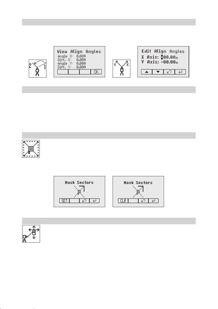
6.6.2 View Align Angles
Selecting the submenu „View Align Angles“showsthealignmentangleafteranaxisalignmenthasbeen
completed. This function can be used to measure an angle difference between two direction hubs in a range
uptomax.80°byperformingtwoaxisalignmentsinsequence.
6.6.3 Edit Align Angles
The submenu „Edit Align Angles“selectionallowstodialinanaxisanglewheretheaxisdirectionwillbe
alignedtooafterarstaxisalignmenthasbeendone.Tworowsareavailablefortypinginaxisanglevalues.
Button5and 8canbeusedtotogglebetweenbothrows.Changingthesignandnumberscanbedoneusing
the buttons 1and 2.
Press and release button 4toconrmtheselectedaxisangles.Theaxeswillbeadjustedwhilethedisplay
fallsbacktothemainMenu.
Press and release button 3(ESC)toexittheAnglefunctions.
6.7 Mask mode
SelecttheMaskicon(Pic32)andpressandreleasebutton4toopentheMasksettingmenu.
Dependingonwhichsideorcornerthebeamshouldbeturnedoff,therequiredsectorcanbe
selected. Press and release the buttons 5to 8formovingashortashinglinearoundthemask
modesymbol.Forselectingthesectorwherethebarisashing,pressandreleasebutton1(SET).
Aftersettingtherstsector,button1changestoshowCLRwhichofferesthecapabilityofdeleting
theselectedmasksectoragain.Usebutton5to 8tomovetheashingbartootherrequiredareas
andrepeatthesettingprocess.Whenallareashavebeenset,pressbutton 4 to store the mask
sector selection until the unit will be turned off.
Note:Theunitalwayspowersupwiththemaskmodedeactivated(default).
6.8 Manual Spot Search mode
The Spot Search mode is used for detecting the plumb beam manually using the Spot Finder
SF601andcanbeactivatedinhorizontalandverticalautomaticandmanualmode.
PressandreleasetheMENUbuttonattheStandardDisplayandselectSpotSearch(Pic33).
Pressing button 4activatesthefanbeamwhiletherotationspeedchangesto750rpmand
the unit goes back to the standard display.
The4redLEDsaroundthecenterholeguidetheusertotheplumbbeam‘scenterposition-all4LEDson=>
conrmationtheSF601hasbeensettothecorrectcenterposition.
ToswitchofftheSportSearchmodepressandreleasetheMENUbuttonandselectSpotSearch(Pic33);
pressing button 4 switches off the Spot Search mode. The regular plumb beam is visible again and the unit
goes back to previous rotation speed.
Note:ManualSpotSearchcanalsobeactivatedanytimebyturningontheSpotFinderSF601.
TurningOfftheSF601deactivatestheSpotSearchmodeimmediatelybydeactivatingthefanbeam.
Pic32
MaskMode
Pic 33
Spot Search

13
6.9 Activating/Deactivating Standby mode
PressandreleasetheMENUbuttonattheStandardDisplayandselectStandby(Pic31).
Pressing and releasing button 4activates the Standby mode.
Theself-levelingwillbestoppedandthebeamwillbeturnedoffwhiletheHIalertisstillactive.
ThedisplayshowsthestandbysymbolandtheLevel/StandbyLEDashesredevery5seconds.
To deactivate Standby mode and restore full operation of the laser, press and release button 4.
6.10 Start Reference Check
Whenworkingduringtemperaturechangesandoverlongdistancestheproductrequiresafrequent
reference check to maintain accuracy and avoid errors caused by drift. The transmitter will do an
automaticuponstartupandafter20minutesofoperation.Itwillrepeatthereferencecheckevery
60minutesandwhenthereisa5°C(9°F)changewithintheproduct.Whencarryingoutworkwhere
accuracy is paramount it is advised to manually prompt a reference check at regular intervals.
PressandreleasetheMENUbuttonattheStandardDisplayandselectReferenceCheck
(Pic35).
Pressing and releasing button 4startstheReferenceCheckconsideringthecurrenttemperatureinside the
housing.Whiletherotorchecksthecorrectpositiontherotationwillbestopped.
Note:Agradevaluehastobeenteredbeforetheunitstartsthereferencecheck.
6.11 Setting Menu
PressandreleasetheMENUbuttonattheStandardDisplayandselectSettings(Pic36).
Press and release button 4toopentheSettingMenu;selectthedesiredfunctionthenpressbutton
4toopentheselectedsubmenufunctionORstarttheselectedfunction.
PleaseseetheSettingMenudetailsattheendoftheuserguide.
6.12 Info
PressandreleasetheMENUbuttonattheStandardDisplayandselectInfo(Pic37).
Buttons6/7canbeusedtotogglebetweenUL,RCandRuntime.
Press and release button 4toconrmtheselection.
TheUL/RCinformation(softwareversion,ID,etc.)ortheruntimeoftheULwillbedisplayed.
Pic 34
Standby
Pic35
Reference
Check
Pic36Settings
Pic37Info
Pic38InfoUL Pic39InfoRC Pic40Runtimes

14
6.13 Service
PressandreleasetheMENUbuttonattheStandardDisplayandselectService(Pic41).Buttons
6/7 can be used to toggle between Calibration Y and Calibration XOR Calibration Z when
set up vertically.
Press and release button 4toconrmtheselection.Thecalibrationattheselectedaxisstartstheeldcalibration
procedure.
6.14 RC603N Service menu:
ThismenuisavailableonlyviatheRC603N.
6.14.1 RF IR options
Choosemenu‚RFIROptions‘(Pic45).Pressandreleasebutton4toconrmtheselectionand
selectoneofthefollowingoptions:
RFOn;IRauto=>Radioonalltimes;IRwillbeactivatedautomaticallyafterradioconnection
has been lost.
RFOff;IROn=>RadioturnedOff;IRalwaysactivated
RFOn;IROff=>RadioturnedOn;IRalwaysOff
Pic46RFOn;
IRAuto
Pic47RFOff;
IROn
Pic48RFOn;
IROff
6.14.2 RF Connectivity
Press and release button 4togetastatusofthecurrentRadioconnectivity(Pic49).
Pic 41
Service
Pic42
CalibrationY
Pic 43
CalibrationX
Pic 44
CalibrationZ
Pic45RFIR
Options
Pic49Radio
Connectivity

15
7 SPECIAL FEATURES - VERTICAL SETUP
7.1 Z-Axis Automatic Spot Align
TheSpotFinderSF601guidestheplumbbeamtothetargetpointinthehorizontalaxis,while
theZ-axisgradevaluewillbemaintained.UsingSpotAlignment,theplumbbeamcanbealigned
automaticallytoonedirectionhub(upto80m(260ft)locatedinfrontoftheplumbbeam.
1. Set up the laser over the start point.
2.Adjustthedisplaybubbletothecenteredposition.
3.TurnonandattachtheSF601SpotFinderatthedesireddirectionhub.
4.PressandreleasetheMENUbuttonattheStandardDisplay;selectSpotAlign(Pic50)andstartthefunction
using button 4(fan beam will be activated).
Note:SpotAligncanalsobestartedusingtheRC603Nviainfrared.
Note:ThedisplayfallsbacktothestandarddisplaywhileaSpotFindersymbol(Pic51)isashing.
Pic51
SpotFinder
TheplumbbeamwillbeautomaticallyalignedtothecenteroftheSF601.
5.Afteralingmentiscomplete(all4redLEDsattheSF601areon),theplumbbeamwillmoveverticallytothe
previousdialedinZ-axisgradevalue.
Note:AutomaticSpotAligncanbeexitedanytimebypressingandreleasingbutton3(ESC).
7.2 Z-axis Automatic Spot Lok
Automatic SpotLok (likePlaneLok)canbeusedtoalignandholdtheplumbbeamautomaticallytotheSF601’s
centerpointandcontinuouslyadjustingtheZ-andX-axisuntilexitingthismode.TheULlooksalwaystothe
centerpositionoftheSF601andre-adjuststhebeamimmediatelytothecentertoavoidanysetup/alignment
driftcausedbyvibrationsortemperatureinuences(e.g.whenworkingonconcretepads,facadeapplications).
UsingSpotLok,theplumbbeamcanbealignedautomaticallytoonedirectionhub(upto80m(260ft)located
in front of the plumb beam.
1. Set up the laser over the start point.
2.PlacetheSF601SpotFinderatthesecondreferencepoint.
3.Press and release the MENU button at the Standard
Display, select SpotLok(Pic52) and start thefunction
using button 4(fan beam will be activated).
Note:SpotLok canalsobe startedviainfrared usingthe
RC603N.
Note:ThedisplayfallsbacktothestandarddisplaywhileaSpotFinderandlockicon(Pic53)isashing.The
plumbbeamwillbeautomaticallyalignedtothecenteroftheSF601.
Pic53
LockMode
4.AfterSpotLokiscompleteall4redLEDsattheSF601areonandtheiconsstopashing.Thetransmitter‘s
plumbbeamisalwayscheckingforperfectalignmenttothecenteroftheSF601.All4LEDsashevery5
secondstoconrmthecorrectalignment.
Note:AutomaticSpotLokcanbeexitedanytimebypressingandreleasingbutton3(ESC).
Pic50
SpotAlign

16
7.3 Z-axis Automatic Spot Match
Automatic-Spot-Match canbeusedformeasuringanunknowngradevaluebetweentwoexistingelevations
e.g.,inanexistingpipewhichneedstobereplacedoranopentrenchwithanunknowngradevalue.
TheplumbbeamwillbeautomaticallyalignedtotheSF601centerpoint(Z-andX-axis)andswitchesback
toautomaticZ-axisgrademodewhiledisplayingthemeasuredZ-gradevalue.
UsingSpotMatch,theplumbbeamcanbealignedautomaticallytoonedirectionhub(upto80m(260ft)
located in front of the plumb beam..
1. Set up the laser over the start point.
2.Place the SF601 Spot Finder at the second reference
point.
3.Press and release the MENU button at the Standard
Display,selectSpotMatch(Pic54)andstartthefunction
using button 4(fan beam will be activated).
Note:SpotMatchcanalsobestartedviainfraredusingtheRC603N.
Note:ThedisplayfallsbacktothestandarddisplaywhileaSpotFinderandanglesymbol(Pic55)isashing.
TheplumbbeamwillbeautomaticallyalignedtothecenteroftheSF601.
Pic55
AngleSymbol
4.WhenSpotMatchhasbeencompleted,thefanbeamwillbeturnedoffandtheULcalculatesthegrade
valuebetweenbothelevationpoints.ThecalculatedgradevaluewillbedisplayedattheUL‘sandRC‘sdisplay.
Note:AutomaticSpotMatchcanbeexitedanytimebypressingandreleasingbutton3(ESC).
7.4 Line Scan
LineScan(Pic56)centerstherotorhorizontallyandcanbeusedtoaligntheplumbbeamto
adesiredhorizontalposition.PressandreleasetheMENUbuttonattheStandardDisplayand
select Line Scan. Pressing and releasing button 4activates the Line Scan mode while the rotor
checksthelimitsoftheX-axisandstopsatthecenterposition.
Pressing button 3(ESC)stopsthemovementandchangestheunitintomanualmode.
Correctionsupanddowncanbedoneusingbutton5/8;forleft/rightcorrectionsusebutton6/7.
Press and release the manual button to change the unit back to full automatic mode.
DuringtheLineScanprocessthecentermovesymbol(Pic57)isashing.
7.5 Beam Plunge
BeamPlungecenterstherotorverticallyandcanbeusedtoaligntheplumbbeamtoadesired
verticalposition,e.g.,whendoingInteriorlayout.
PressandreleasetheMENUbuttonattheStandardDisplayandselectBeamPlunge(Pic58).
Pressing and releasing button 4activatestheBeamPlungemodewhiletherotorchecksthelimits
oftheY-axisandstopsatthecenterposition.
Pressing button 3(ESC)stopsthemovementandchangestheunitintomanualmode.
Correctionsupanddowncanbedoneusingbutton5/8;forleft/rightcorrectionsusebutton6/7.
Press and release the manual button to change the unit back to full automatic mode.
Pic56
Line Scan
Pic57
CenterMove
Pic58
BeamPlunge

17
8 Settings
PressandreleasetheMENUbuttonattheStandardDisplayandselectSettings(Pic59).
Press and release button 4toopentheSettingMenu;selectthedesiredfunctionthenpressbutton
4toopentheselectedsubmenufunctionORstarttheselectedfunction.
TheSettingMenuoffersthefollowingfunctions:
Pairing Grade Entry Grade Display Sensitivity
HI-Alert
User Name Set Password Password On/Off RF-Channel
Select
Language
Position Info
8.1 Pairing
Pairing is needed to couple different devices with the laser. The laser is able to communicate with
several numbers of other radio network participants and pairing is the process to link these to each
other.Buyingthelaseralldevicesshouldbepairedbutforsomereasonsthismaynotbetrue
or the pairing has been lost. So you can pair the devices as described in the following sections.
Note:Makesurethatpairingmodeisselectedonlyatonelaserwhichiswithintheradiorangeoftheremote
duringapairingrequest.Otherwisepairingprocedurecanbeconfused.
8.2 Pairing the laser with remote control
Startwiththelaser.WheninmenuSettings(Pic59),pressandreleasebutton4toopenthepairingmenu
(Pic71).Thedisplayshowsthecurrentlypairedunits(uptotworemotes).MakesureatleastoneRCslotis
freefortheremotetobepaired.IfnofreeRCslotisavailable,chooseoneofthemanddeleteitusingbutton
1(CLR).Pressbutton2tostartthepairingprocess.Continuewiththeremotechoosingthesymbolpairing
(Pic71);thepairingstartsautomatically.Aftersuccessfulpairing,thelaserdisplayshowstheIDoftheremote
in the pairing list.
8.3 Pairing the laser with receiver HL760
To pair the laser and the receiver select Settings and press and release button 4to open the Pairing menu (Pic
71).Thedisplayshowsthecurrentlypairedunits(upto2receivers).Ifalready2receivershavebeenpaired,
one or both of them have to be deleted using button 1(CLR).
Pic59
Settings
Pic71Pairing

18
A
B
C
Next,turnonthereceiverthenpressandholdtheDeadband(A)andtheAudio(B)buttonsfortwoseconds.
AftertwosecondsthedisplayshowsMENUrst,thenRDIO.
PressandreleasetheUnits(C)button–displayshowsthecurrentradiomode.
IfnotalreadysettoLS,pressUnitsbuttonandthenpressDeadbandorAudiobuttonuntilLS is displayed.
PressUnitsbuttonagaintoenterselection.PressandreleasetheAudiobutton–displayshowsPAIR.Press
theUnitsbuttonagain–thedisplayshowsPAIRandarotatingbar.AftercompletingPAIR,OKwillbedisplayed.
TheUL633Npairsnowautomaticallywiththenewreceiver.PressandreleasethePowerbuttontwotimesto
exitthemenu.Alasersymbolislittoconrmthereceivercancommunicatewiththelaser.
8.4 Pairing the laser with the signal transporter (ST802/ST805)
MakesuretheST802/ST805isswitchedoff.StartwiththeLaser.WheninmenuSettings(Pic59),pressand
releasebutton4toopenthepairingmenu(Pic71).Thedisplayshowsthecurrentlypairedunits(onesignal
transportermax).MakesuretheSTslotisfreeforthesignaltransportertobepaired.Iftheslotisnotfree,
choosetheSTslotanddeleteitusingbutton1(CLR).Pressbutton2tostartthepairingprocess.Switchon
thesignaltransporter.Thesignaltransporterpairsautomaticallywiththelaser.Ifthepairingwassuccessful
theaddressorIDofthepairedSTisshowninthepairinglist;alsothesignaltransportershowsasolidblinking
yellowstatusLED.
8.5 Grade Entry
SelecttheGradeEntryicon(Pic73)andpressandreleasebutton4toopentheGradeEntrymenu.
Buttons6/7canbeusedtotogglebetweenStepandGo(Pic74)andDigitSelect(Pic75).
Press and release button 4toconrmtheselection.
Pic 74
Step and Go
Pic 75
Digit Select
8.6 Grade Display
SelecttheGradeDisplayicon(Pic76)andpressandreleasebutton4toopentheGradeDisplay
menu.
ThedesiredGradeDisplayMode(Percent(Pic77)/Permille(Pic78)/Degree(Pic79))canbe
selected using the buttons 6/7. Press and release button 4toconrmtheselecteddisplaymode.
Pic73
GradeEntry
Pic76
GradeDisplay
Pic78
Per mill
Pic77
Percent
Pic79
Degree
Other manuals for Trimble UL 633N
1
Table of contents
Other Spectra Precision Laser Level manuals

Spectra Precision
Spectra Precision LL300S Instruction manual

Spectra Precision
Spectra Precision LL300S User manual

Spectra Precision
Spectra Precision GL6X2N Installation guide

Spectra Precision
Spectra Precision LL300S User manual

Spectra Precision
Spectra Precision GL412N User manual

Spectra Precision
Spectra Precision LL100N Assembly instructions

Spectra Precision
Spectra Precision AL28M User manual

Spectra Precision
Spectra Precision HV302 User manual

Spectra Precision
Spectra Precision HV302 User manual

Spectra Precision
Spectra Precision Trimble UL 633N Installation guide


