Spectra Vista Corporation i Series User manual

SVC i-SERIES
UNDERWATER HOUSING
USER MANUAL
Revision 2.3.1
29 Firemens Way, Poughkeepsie, New York 12603
Copyright 2019 Spectra Vista Corporation


Table Of Contents
Overview....................................................................................................................... 1
Handles ......................................................................................................................... 4
Clear Panels .................................................................................................................. 4
Controls......................................................................................................................... 5
Installation – Instrument Into Enclosure ASM512-500 / ASM1024-500..................... 6
SPECIAL NOTE – Enclosure Leak Check ................................................................ 15
Removal of the Instrument from the Housing ............................................................ 15
Ballast Weights........................................................................................................... 18
Specifications – ASM512-500 / HR-512i................................................................... 19
Consumable Parts List – ASM512-500 ...................................................................... 19
Specifications – ASM1024-500 / Full-Range Instruments......................................... 20
Consumable Parts List – ASM1024-500 .................................................................... 20

Table of Figures
Figure 1 ASM512-500 Housing, Rear View ................................................................ 1
Figure 2 ASM1024-500 Housing, Rear View .............................................................. 2
Figure 3 ASM512-500 Housing, Front View............................................................... 3
Figure 4 ASM1024-500 Housing, Front View ............................................................. 3
Figure 5 Rear Controls (ASM512-500 and ASM1024-500) ........................................ 5
Figure 7 Trim Blocks (Right Side Shown) Installed .................................................... 6
Figure 6 Instrument Lifting Eye Replacement.............................................................. 6
Figure 8 Alignment Probe Installed On Instrument Base Plate.................................... 7
Figure 9 Instrument Prior To Rear Panel Installation................................................... 8
Figure 10 HR-512i Instrument After Rear Panel Installation....................................... 8
Figure 11 HR-1024i Instrument After Rear Panel Installation..................................... 9
Figure 12 Instrument Battery Installed ......................................................................... 9
Figure 13 Rear Panel Pre-Installation Test................................................................. 10
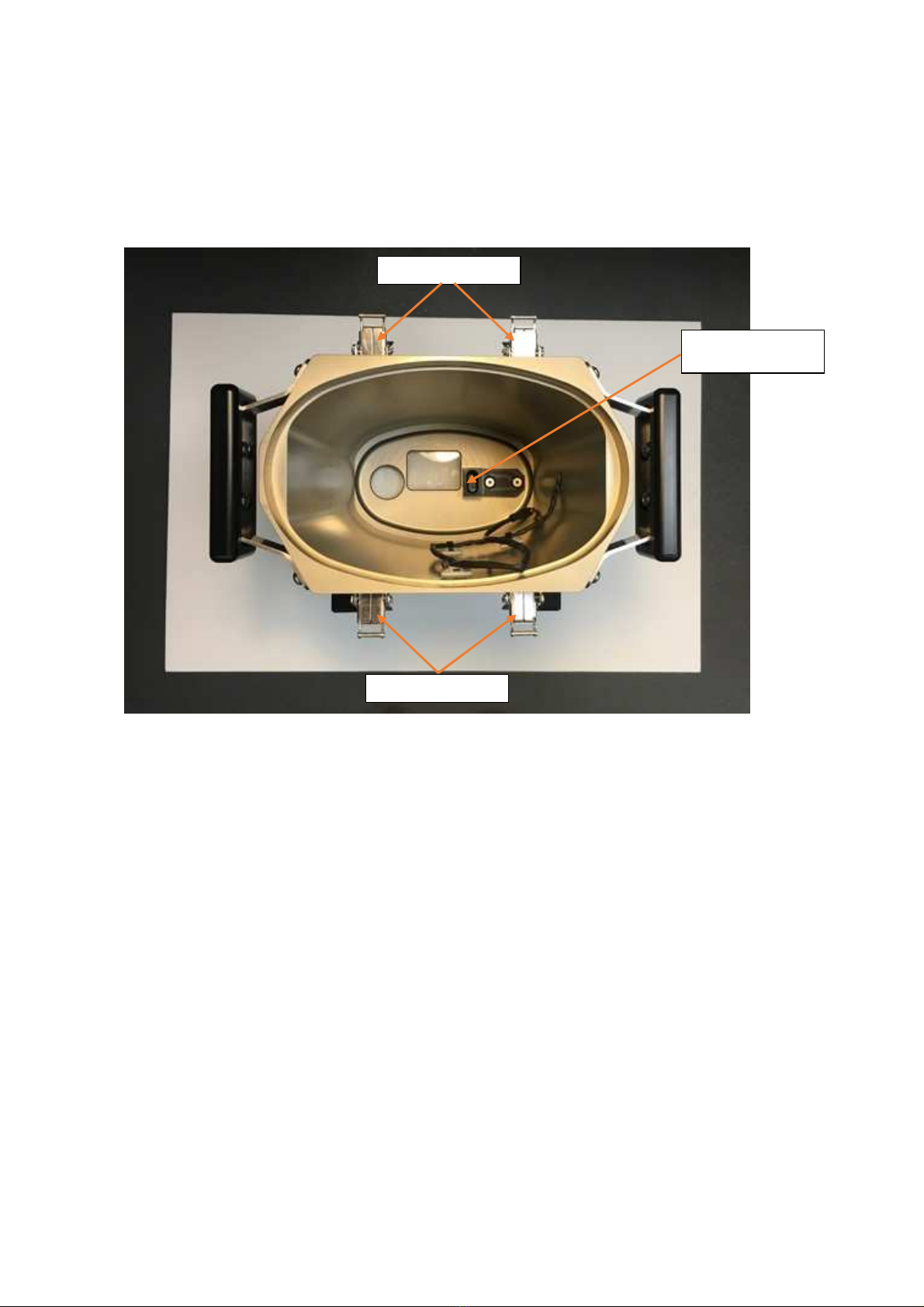
Figure 14 View Down Into Enclosure........................................................................ 11
Figure 15 Connecting Cabling.................................................................................... 12
Figure 16 Lowering Rear Panel Assembly Into Enclosure......................................... 13
Figure 17 Rear Panel Inserted Into Enclosure ............................................................ 14
Figure 18 Draw Latch, Used for Rear Panel Extraction............................................. 16
Figure 19 Using Jackscrews To Extract Rear Panel................................................... 17
1
Overview
This User Manual applies to the following SVC products:
ASM512-500 Underwater Housing for SVC HR-512i Spectroradiometers
ASM1024-500 Underwater Housing for SVC i-Series full-range Spectroradiometers
The Underwater Housing provides a secure and convenient means to conduct submerged data
collections at depths of up 40 meters (130 feet) in either salt or fresh water.
The standard 4° foreoptic and the standard battery are used for operations with the instrument
installed in the Underwater Housing. One battery should supply sufficient power for a full
day’s data collection (SVC HR-512i instrument) or 3 hours of data collection (SVC i-Series
full-range instruments).
Data collected during each dive may be downloaded via Bluetooth without opening the
housing, thus minimizing the risk of getting moisture into the housing or onto the instrument.
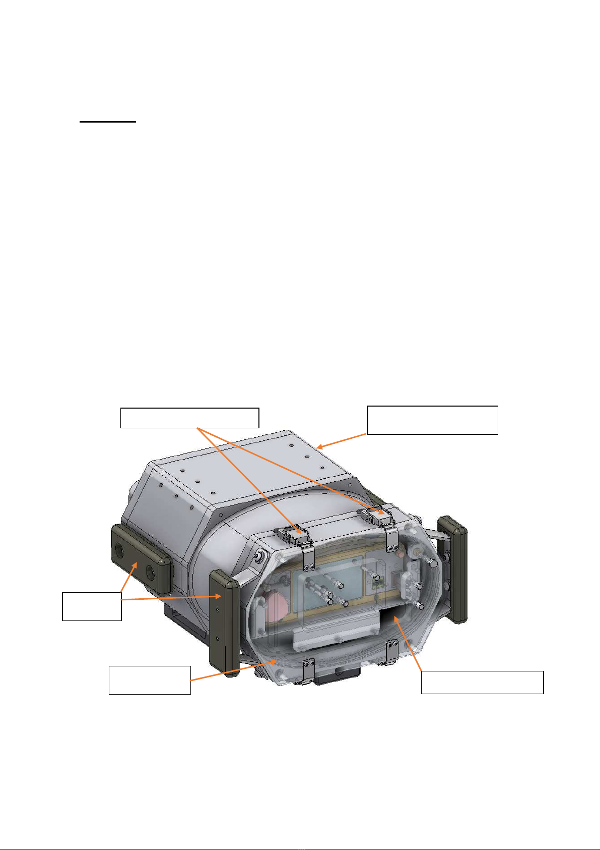
The removable rear panel, which is constructed of robust clear acrylic, is quickly detachable.
Four stainless steel draw latches are used to compress a pair of O-rings, affecting a secure,
watertight seal between the rear panel and the main housing (shown in Figures 1 and 2).
REAR ACRYLIC PANEL
ANODIZED ALUMINUM
HOUSING
O-RING SEALS
(2 TOTAL)
DRAW LATCHES (4 TOTAL)
HANDLES
(4 TOTAL)
Figure 1 ASM512-500 Housing, Rear View

2
Figure 2 ASM1024-500 Housing, Rear View
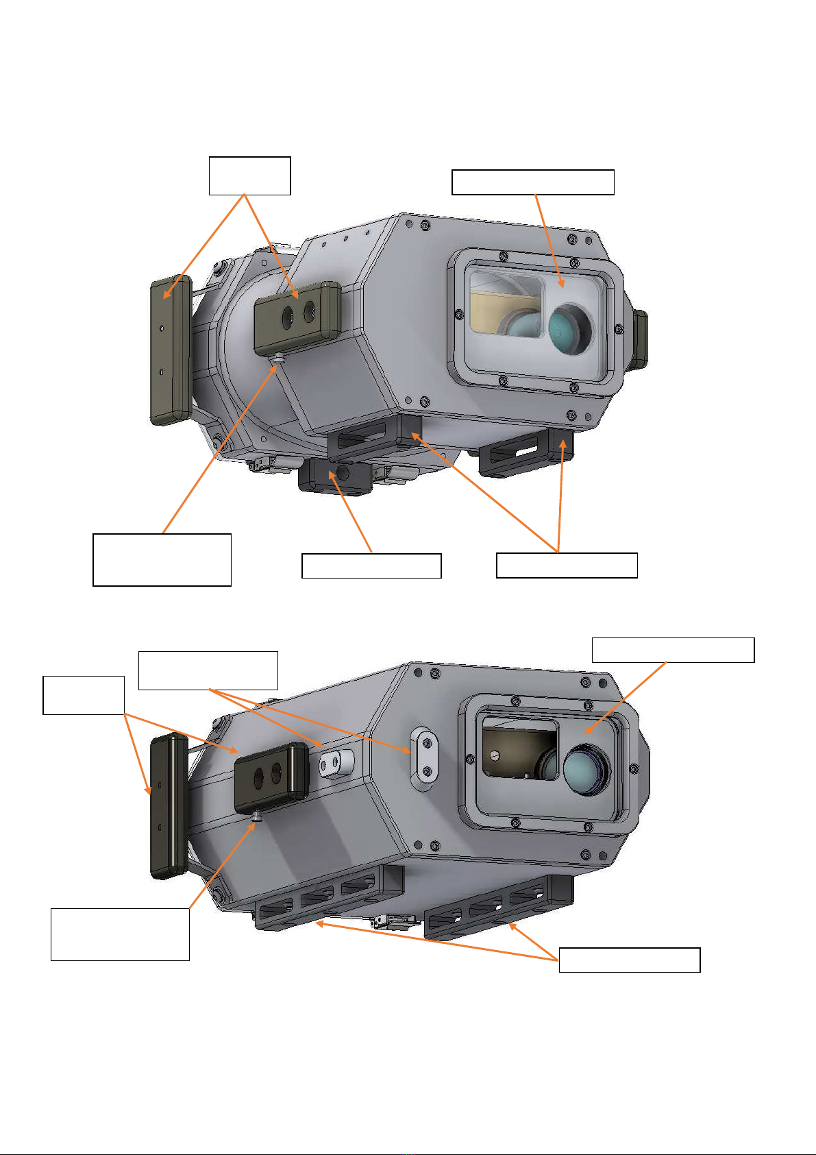
The front optical glass port is also sealed with an O-ring, and is semi-permanently installed
(shown in Figures 3 and 4).
The main body of the housing is made of clear anodized aluminum alloy and is rated for
operations to a water depth of forty meters. The enclosure is designed for appropriately
displaced water volume, resulting in neutral to slightly positive buoyancy.
A pair of protective, black anodized skids are attached to the bottom of the housing. The skids
also double as locations for adding diving weights, to counteract any excess buoyancy of the
submerged enclosure with the instrument installed (shown in Figures 3 and 4).
Although all hardware used is top-quality stainless steel alloy, it is recommended that the
housing be rinsed off with fresh water after each diving session, prior to drying and opening.
Sacrificial zinc weights attached to the surface of the housing helps to safeguard against
corrosion (also shown in Figures 3 and 4).
REAR ACRYLIC PANEL
O-RING SEALS
(2 TOTAL)
HANDLES
(4 TOTAL)
DRAW LATCHES (4 TOTAL)
ANODIZED ALUMINUM
HOUSING
SACRIFICIAL ZINC
(3 TOTAL)
3
Figure 3 ASM512-500 Housing, Front View
SACRIFICIAL ZINC PROTECTIVE SKIDS
TARGET
ACQUISTION
PUSHBUTTON
HANDLES
(4 TOTAL)
FRONT OPTICAL PORT
Figure 4 ASM1024-500 Housing, Front View
PROTECTIVE SKIDS
SACRIFICIAL ZINC
(3 TOTAL)
TARGET
ACQUISTION
PUSHBUTTON
HANDLES
(4 TOTAL)
FRONT OPTICAL PORT

4
Handles
Two sets of handles are provided to facilitate operation of the submerged unit in either a
horizontal or a vertical orientation. The handles are held in place with stainless socket head cap
screws. On the right-hand side handle, a waterproof pushbutton switch, operated by the diver’s
thumb, has been incorporated to acquire spectral scans when the instrument is located
vertically, with the optical port at the bottom.
Clear Panels
The rear panel or endplate of the enclosure is constructed of transparent acrylic. This ensures
easy viewing of the instrument’s rear touchscreen LCD and controls. It is secured with four
over-center latches, used to provide the necessary seal squeeze, and sealed with a pair of
AS568-266 oil-resistant Buna-N O-rings.
The seal lines between the rear acrylic panel and main housing are visible, so as to provide a
convenient means of visually checking the sealing integrity of the Buna-N O-rings.
Caution: Always verify that the thin, black seal lines from the O-rings’ squeeze can be
seen through the rear panel. If not, determine the cause of the problem and
correct it before submerging the housing.
The front viewing port is constructed of 0.75-inch thick optical glass, sealed with one oil-
resistant Buna-N O-ring. It is not recommended that this seal be removed and reinstalled
unless unit is to be placed in storage for an extended period of time.
Always use a very light coat of silicon grease, such as Dow Corning Molykote 111 compound
when servicing the O-ring seals. Apply by hand, by wiping. Rubber gloves are recommended.
A small supply of this lubricant, a set of replacement O-rings and a removal tool are shipped
with the housing.
Both transparent panels are designed to withstand depths of up to forty meters (130 ft.).
Caution: Exercise care when removing front window retainer or seal.
The optical glass front viewing port is not fastened to the retaining ring.
Do not allow it to fall out and become damaged.

5
Controls
When the instrument is installed within the Underwater Housing, the touch-screen controls are
accessed via a set of specially-designed, sealed actuator pins (aka plungers), using a design
which has been well-proven in the field.
These plungers are incorporated into the rear acrylic panel (shown in Figure 5).
The plungers are used by the diver to operate the menus on the LCD panel on the rear of the
instrument. This LCD panel incorporates a multi-position, resistive touchscreen. Five plungers
have been provided for the touchscreen. Two additional plungers have been provided to
operate the ON/OFF rocker switch, located on the right-hand side of the instrument rear panel.
One additional plunger is found on the right-hand side of the transparent rear panel, a
waterproof pushbutton switch. This plunger is operated by the diver’s thumb, and has been
incorporated to take spectral scans when the instrument is oriented horizontally.
This brings the total number of plungers to eight. Each plunger head retracts into a counter-
bore on the exterior of the acrylic panel, which serves as a means of limiting the plunger’s
travel. The plungers also have soft tips which contact the screen. Both features have been
incorporated to avoid any damage to the touchscreen. Note that when installed in the provided
tray, the instrument’s LCD touchscreen is always correctly located, so as to accurately align
the plungers with their corresponding LCD touchscreen button locations.
TOUCHSCREEN PLUNGERS
ON/OFF
PLUNGERS
TARGET
ACQUISITION
PLUNGER
Figure 5 Rear Controls (ASM512-500 and ASM1024-500)

6
Installation – Instrument Into Enclosure ASM512-500 / ASM1024-500
Confirm that the two P/N MAC1024157 stainless steel lifting eyes (shown in Figure 6) have
been removed from the instrument prior to installing it in the Underwater Housing.
The lifting eyes are replaced by two aluminum trim blocks (P/N MAC1024166). (See Figure
7), secured with the original lifting eyes’ #6-32 x 3/8” (P/N HDW001033) stainless steel
machine screws.
The lifting eyes are removed in order to permit the installation of the instrument in a position
as close as possible to the rear acrylic panel of the Underwater Housing.
Figure 7 Trim Blocks (Right Side Shown) Installed
ORIGINAL
LIFTING EYES
TRIM BLOCKS
(P/N MAC1024166)
Figure 6 Instrument Lifting Eye Replacement
7
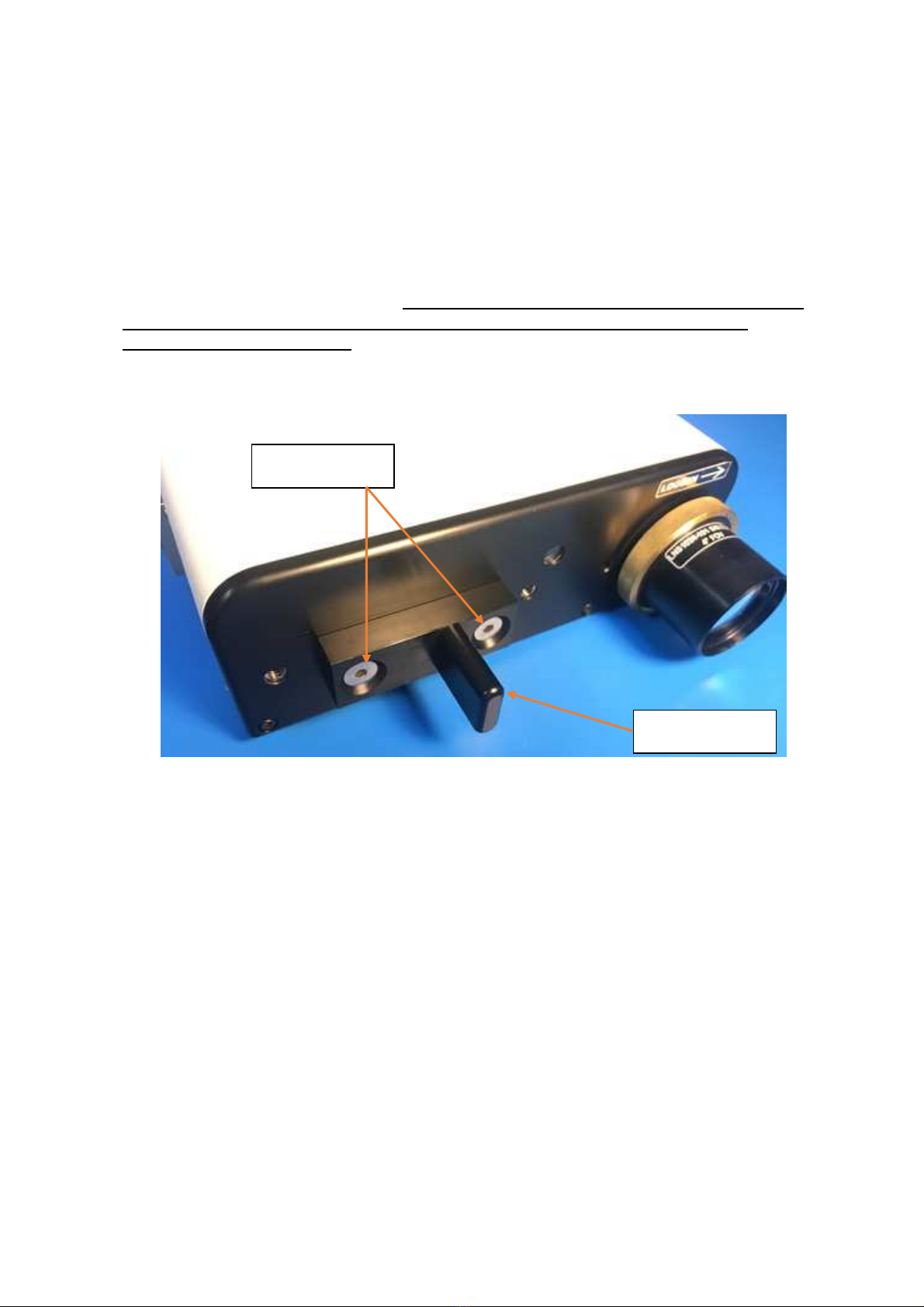
Install the instrument Alignment Probe onto the instrument base plate using two of 1/4-20 x
0.625” Hex Socket Head Flat Countersunk screws as shown below (See Figure 8). The
alignment probe mates with the Alignment Fixture that is mounted within the Underwater
Housing. This fixture holds the instrument’s front plate rigidly in place within the Underwater
Housing.
When installing the Alignment Probe, carefully note its orientation and placement; it must
be placed exactly as shown in order to mate correctly with the Alignment Fixture
mounted within the enclosure.
Make sure that the lens cover has been removed from the instrument’s foreoptic.
Figure 8 Alignment Probe Installed On Instrument Base Plate
¼-20 x 0.625”
FASTENERS
ALIGNMENT
PROBE

8
8-32 x 3/8”
THUMBSCREWS
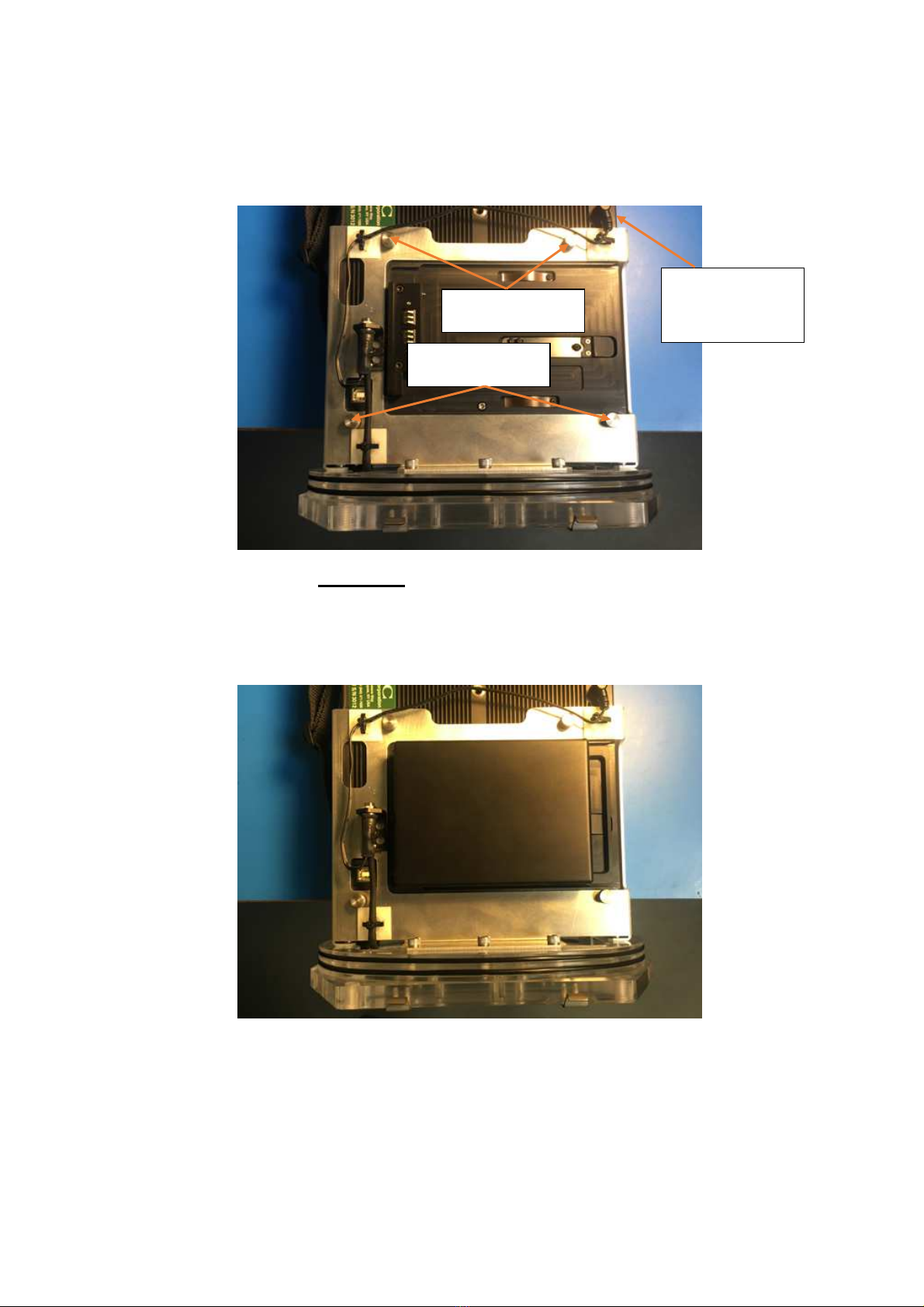
Turn the instrument upside down, and gently place it on a table near an edge (See Figure 9) in
order to install the Enclosure Rear Panel. Hang about 1 inch of the instrument over the edge.
Figure 9 Instrument Prior To Rear Panel Installation
Place the Rear Panel over the bottom of the instrument, and fasten it to the instrument using
four thumbscrews (See Figure 10 – HR-512i or Figure 11 – HR-1024i). Also connect the
Interconnect Cable to the mate on the instrument’s Optical Plate.
Figure 10 HR-512i Instrument After Rear Panel Installation
INTERCONNECT
CABLE PLUGS
INTO OPTICAL
PLATE
9
Figure 11 HR-1024i Instrument After Rear Panel Installation
Slide a fully-charged battery into the assembly (See Figure 12). The Rear Panel assembly onto
the instrument is now complete.
Figure 12 Instrument Battery Installed
8-32 x 3/8”
THUMBSCREWS
6-32 x 3/8”
THUMBSCREWS
INTERCONNECT
CABLE PLUGS
INTO OPTICAL
PLATE

10
Now turn the Rear Panel assembly over, so that the instrument is oriented as shown below (See
Figure 13).
Turn on the instrument and operate all of the controls and LCD plungers in order to confirm
that they all work properly. Do this test prior to installing the Rear Panel assembly into the
enclosure.
Check that battery is fully charged by observing the LCD area below the “BAT” label; this
area displays the remaining percentage battery charge and should read close to 100% at the
start of a dive.
POWER ON
POWER OFF
LASER /
TRIGGER
Figure 13 Rear Panel Pre-Installation Test
BATTERY
CHARGE
PERCENTAGE
11
Place the enclosure on the floor facing upwards, as shown below (See Figure 14). The four
draw latches should be wide open and the internal trigger cable should be pulled free and its
connector made ready to attach to the mating connector on the bottom of the rear panel tray.
Look down into the enclosure and note the position of the Alignment Receiver. This structure
receives the corresponding Alignment Probe that is mounted to the instrument’s base plate (as
shown in Figure 8).
DRAW LATCHES
DRAW LATCHES
ALIGNMENT
RECEIVER
Figure 14 View Down Into Enclosure

12
While one person holds the Rear Panel / Instrument assembly just above the enclosure opening,
have a second person connect the internal trigger cable connector to its mate on the bottom of
the Rear Panel. (See Figure 15).
INTERNAL
TRIGGER CABLE
CONNECTOR
Figure 15 Connecting Cabling

13
Continue lowering the Rear Panel / Instrument assembly down into the enclosure (See Figure
16). Take care that neither the cabling nor the instrument’s cloth hand strap becomes pinched
as the assembly is lowered down into the enclosure.
Note that in order for the Alignment Probe to settle into the Alignment Receiver, the assembly
may have to be tilted back/forth during the last 2-3 centimeters until the two parts engage
correctly.
Figure 16 Lowering Rear Panel Assembly Into Enclosure

14
When they have engaged, the assembly will come to rest on the first O-ring as shown below
(See Figure 17).
The assembly is completed by firmly pressing down on the Rear Panel handles until it is fully
inserted into the enclosure, and then engaging the four Draw Latches. Be certain to keep the
rear panel parallel to the rear surface of the enclosure as it is being inserted.
When installing the Rear Panel, check that no objects are lying across the seal area. Also
verify that the seals are properly placed in the O-ring grooves, with nothing under them,
and confirm that they are not pinched when pulling the latches down. Make certain that
the seal lines, seen as two dark stripes where the O-rings contact the clear acrylic, are
visible and continuous.
Figure 17 Rear Panel Inserted Into Enclosure

15
SPECIAL NOTE – Enclosure Leak Check
While each housing has been water tested for leaks prior to shipment, it is strongly
recommended (owing to the cost of the Spectroradiometer) that the empty housing be “bounce
dived” to the maximum expected working depth prior to the unit’s first use after shipping or
after storage for any extended period. Simply roll up some loose paper towels, place them in
the housing, add weight to compensate for the absent unit’s weight and take it down. Thin,
absorbent paper is a great indicator, as water leaks can be quickly identified. Always be sure
to rinse with clear water and remove any excess water from the exterior, prior to opening the
housing.
Note: If any leak is found, the cause must be identified and corrected prior to using the
housing with the instrument.
In the very unlikely event that a rear panel “O” Ring seal leak is noticed during use (by
observing water droplets on the inside portion of the panel), immediately rotate the housing
unit to a horizontal position and take it to the surface. Maintain this horizontal position even
when lifting it from the water.
Note: Always remove excess water from the housing prior to removing the rear
endplate.
Removal of the Instrument from the Housing
This operation is basically the reverse of the installation sequence described previously. It is
best performed on a clean, padded surface, to avoid accidental damage to any components.
After ensuring that excess moisture has been removed from the external surfaces of the
underwater housing, release the four draw latches. Please note that there are small, raised latch
release tabs which must be depressed prior to opening the draw latches. These tabs are a
precaution against accidental release. (See Figure 18).
After releasing the latches, withdraw the rear panel/tray assembly. There will be some friction
from the sealing O-rings. Try to withdraw the assembly evenly. If there is too much resistance
to removal, the latches may be used to assist in extracting the rear panel/instrument assembly
from the housing. After the rear panel has been withdrawn sufficiently, the cylindrical
crossbars of the latches can be moved to a position on the back side of the corresponding latch
hooks. Depressing the draw latch levers will then push the cross bar against the back of the
latch hook, safely easing the rear panel from the housing. (See Figure 18).
Note: DO NOT ATTEMPT TO PRY THE REAR PANEL FROM THE MAIN
HOUSING by using a screwdriver or similar metal tool. Damage may result.

16
Figure 18 Draw Latch, Used for Rear Panel Extraction
LATCH HOOK
DRAW LATCH
CROSS BAR
DRAW LATCH
RELEASE TAB
Table of contents
Other Spectra Vista Corporation Camera Accessories manuals

Popular Camera Accessories manuals by other brands


Trojan
Trojan GC2 48V quick start guide

Calumet
Calumet 7100 Series CK7114 operating instructions

Ropox
Ropox 4Single Series User manual and installation instructions

Cambo
Cambo Wide DS Digital Series Main operating instructions

Samsung
Samsung SHG-120 Specification sheet

Ryobi
Ryobi BPL-1820 Owner's operating manual