Spectracom VersaPNT User manual
VersaPNT
Getting Started Guide
Document Part No.: 1228-5000-0057
Revision: 2.0
Date: 5-September-2018

About this Guide
This Getting Started Guide is a supplement to the main user manual for VersaPNT. The latest ver-
sion of the main user manual can be found online under manuals.spectracom.com.
© 2018 Spectracom. An Orolia brand.
Orolia USA, Inc. dba Spectracom
2CHAPTER 1•VersaPNT Getting Started Guide Rev. 2.0

CONTENTS
VersaPNT Getting Started Guide • TABLE OF CONTENTS i
Product Overview 1
1.1 Interfaces Overview 1
1.1.1 Input Timing Interfaces 2
1.1.2 Output Timing Interfaces 2
1.1.3 Navigation Inputs & Outputs 2
1.1.4 Other Interfaces 3
1.2 Connectors and their Pinouts 4
1.2.1 Power Connector 4
1.2.2 Input/Output Connector 4
1.2.3 Ethernet Connector 5
1.2.4 Optional I/O Connector 6
1.2.5 Coaxial Connectors 6
1.3 Included Cables 7
1.4 Status LEDs 9
1.4.1 Blinking Intervals 9
1.4.2 LED Lighting Patterns 9
1.4.3 Legend, individual LEDs 10
1.4.3.1 LED Patterns during Boot Sequence 11
1.4.4 Blackout Mode 11
1.5 The VersaPNT Web UI 11
1.5.1 The Web UI HOME Screen 11
Quick Start 13
2.1 Network Setup 14
2.2 Zero Configuration Setup 19
2.2.1 Using Zeroconf 20
2.3 Assigning I/O Pins 21
2.3.1 Signal Types 21
2.3.2 I/O Signal Mapping Table 22
2.4 INS Configuration 26
2.4.1 "IMU Output" Tab 27
2.4.2 "Calibration" Tab/Antenna Installation 29

2.4.3 "Log" Tab 31
2.4.4 "FIR Filter" Tab 31
2.4.5 "Coning/Sculling" Tab 32
2.4.6 "Frame Rotation" Tab 33
2.5 INS Initialization 34
2.6 INS Expert Mode 35
2.7 VICTORY Configuration 36
SAFETY 37
3.1 SAFETY: Before You Begin Installation 37
Technical Support 39
4.1 Regional Contact 39
ii VersaPNT Getting Started Guide • TABLE OF CONTENTS
Product Overview
This section is designed to help you become familiar with the structure, features, and functions
of the VersaPNT.
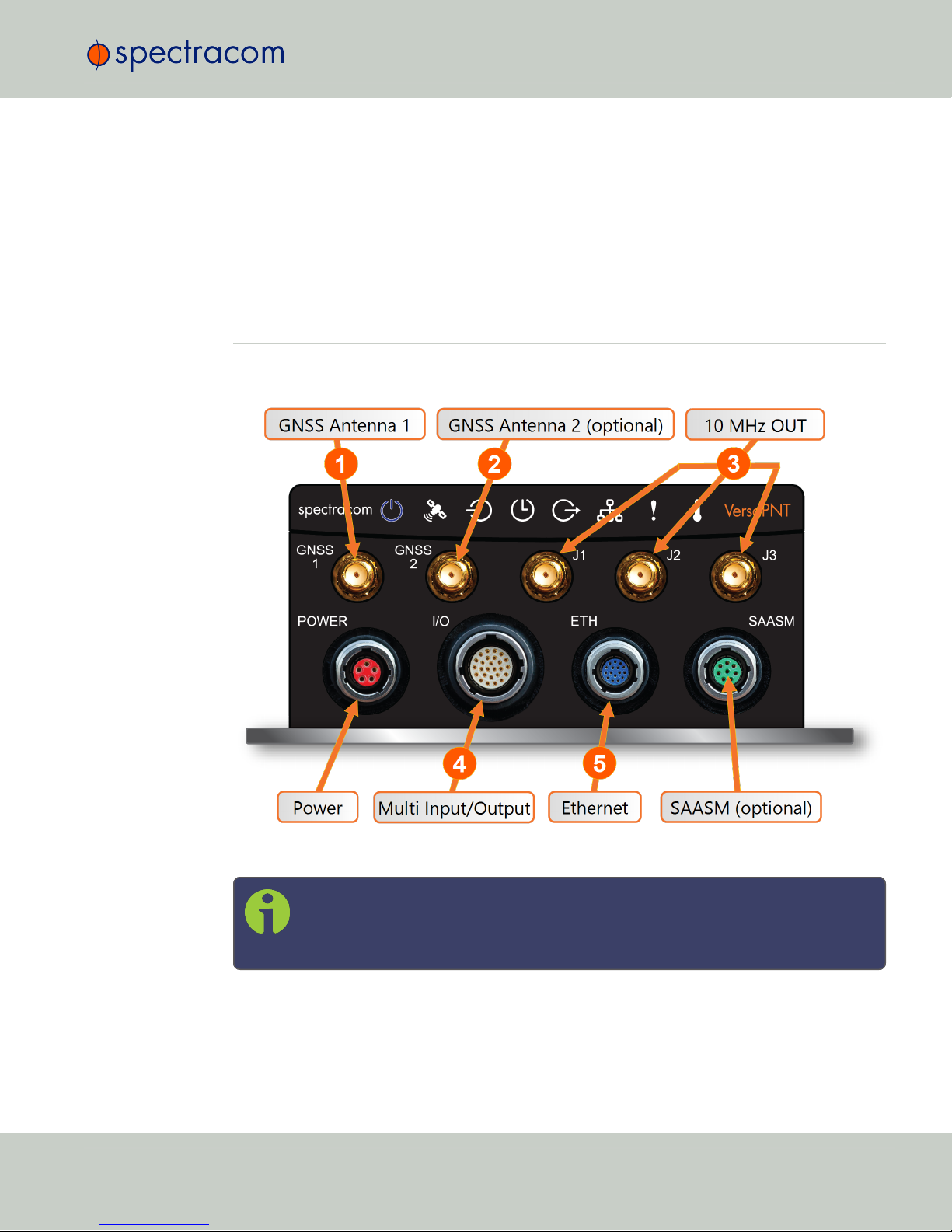
1.1 Interfaces Overview
All of VersaPNT's interfaces are integrated into the unit's connectors, which are located on the
front panel:
Figure 1-1: VersaPNT front panel connectors
Note: VersaPNT is highly configurable and the connections can be adjusted many
different ways. Your interface configuration may vary based on options you selec-
ted during the ordering process.
The following interfaces are provided:
1.1 Interfaces Overview
CHAPTER 1•VersaPNT Getting Started Guide Rev. 2.0 1
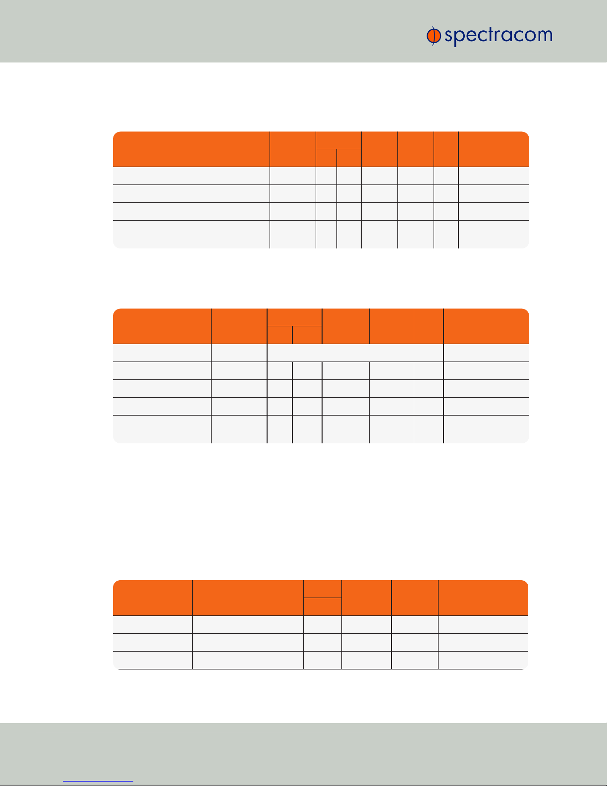
1.1.1 Input Timing Interfaces
Table 1-1: VersaPNT timing inputs
INPUTSIGNAL Total
available
DCLS RS-232 RS-485 ETH Connector No.
(see Fig. above)
TTL 10V
1PPS (1) 1 4
ASCII/HaveQuick/IRIG B (1) 1 4
ASCII/NMEA (1) 1 4
Network Interface (10/100/1000bT):
NTP (Stratum 2), PTP
(2) 1 5
1.1.2 Output Timing Interfaces
Table 1-2: VersaPNT timing outputs
OUTPUTSIGNAL Total
available
DCLS RS- 232 RS-485 ETH Connector No.
(see Fig. above)
TTL 10V
10 MHz (1+3) SMA 3
1PPS (2) 1 1 4
ASCII/HaveQuick (1) 1 4
ASCII/NMEA (1) 1 4
NTP server,
PTP v2 master
(1) 1 5
All Multi I/O interfaces (connector no. 4) are software-configurable, see "Assigning I/O Pins"
on page21.
1.1.3 Navigation Inputs & Outputs
The following VersaPNT options apply to the INS option board. The standard INS
OUTconnection will communicate your position and navigation information, while the Options
1-8 provide additional information via the multi I/O connector:
Table 1-3: Navigation input and output options
SIGNAL TYPE Option Number/
Channel Position
DCLS RS- 232 RS-422
(n or p)
Connector No.
(see Fig. above)
TTL
INS OUT Channels 1, 4, & 6 1 4
PPS IN Option & Channel 1 1 4
PPS OUT Option & Channel 2 1 4
2CHAPTER 1•VersaPNT Getting Started Guide Rev. 2.0
1.1 Interfaces Overview
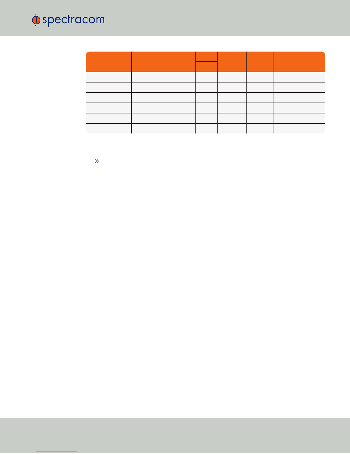
SIGNAL TYPE Option Number/
Channel Position
DCLS RS- 232 RS-422
(n or p)
Connector No.
(see Fig. above)
TTL
GPS IN Option & Channel 3 1 4
GPS OUT Option & Channel 4 1 4
IMU IN Option & Channel 5 1 (p) 4
IMU IN Option & Channel 6 1 (n) 4
IMU OUT Option & Channel 7 1 (p) 4
IMU OUT Option & Channel 8 1 (n) 4
1.1.4 Other Interfaces
USB serial equivalent: CLI interface (Connector 4)
1.1 Interfaces Overview
CHAPTER 1•VersaPNT Getting Started Guide Rev. 2.0 3

1.2 Connectors and their Pinouts
All of VersaPNT's connectors are provided at the front panel of the unit, below the Status LEDs.
1.2.1 Power Connector
Note: View in mating direction from front.
Table 1-4: Power connector pinout
Pin Signal
1 VMain (10 to 32V)
2 VMain (10 to 32 V)
3 VBatt (10 to 32 V)
4 GND
5 GND
1.2.2 Input/Output Connector
VersaPNT has a 26-pin input/output connector that offers 8 software-configurable CHANNELS,
plus one fixed DCLS channel, and a USB interface. To learn more about types of interfaces and
signals, and how to configure them, see "Assigning I/O Pins" on page21.
4CHAPTER 1•VersaPNT Getting Started Guide Rev. 2.0
1.2 Connectors and their Pinouts

Table 1-5: Default I/O connector pinout
Pin Channel Signal Pin Channel Signal
10 1PPS output (5V) 15 7 Have Quick output (RS-
485 signal +)
2GND 16 GND
31 HaveQuick input (RS-
485 signal +)
17 8 Have Quick output (RS-
485 signal –)
4GND 18 GND
52 HaveQuick input (RS-
485 signal –)
19 9
(USB ded-
icated)
GND
6GND 20 GND
73 1PPS output (10 V) 21 Not connected
8GND 22 GND
94 ASCII output (RS-232) 23 USB D–
10 GND 24 GND
11 5 1PPS input 25 USB D+
12 GND 26 GND
13 6 ASCII input (RS-232)
14 GND
1.2.3 Ethernet Connector
Note: View in mating direction from front.
1.2 Connectors and their Pinouts
CHAPTER 1•VersaPNT Getting Started Guide Rev. 2.0 5
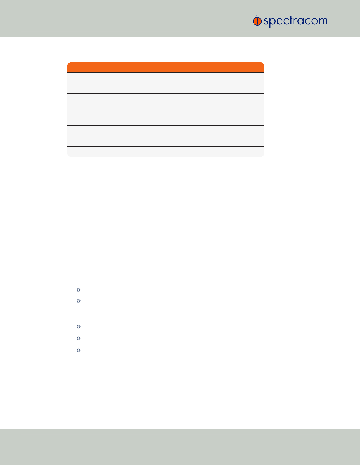
Table 1-6: Ethernet connector pinout
Pin Signal Pin Signal
1 Ethernet_1 A+ 9 Ethernet_2 A+
2 Ethernet_1 A– 10 Ethernet_2 A–
3 Ethernet_1 B+ 11 Ethernet_2 B+
4 Ethernet_1 B– 12 Ethernet_2 B–
5 Ethernet_1 C+ 13 Ethernet_2 C+
6 Ethernet_1 C– 14 Ethernet_2 C–
7 Ethernet_1 D+ 15 Ethernet_2 D+
8 Ethernet_1 D– 16 Ethernet_2 D–
1.2.4 Optional I/O Connector
The Optional I/O connector is used in conjunction with the Option Board that is available for
VersaPNT. If the unit is not equipped with an Option Board, this connector is not used.
1.2.5 Coaxial Connectors
VersaPNT offers five (5) coaxial connectors, three (3) of which can be configured at the factory
to accommodate requirements for e.g., IRIG AM signals or additional 10MHz outputs. The min-
imum configuration includes the GNSS antenna and a 10MHz sinewave output.
Unless otherwise ordered at the factory, all coaxial connectors (aside from the GNSS con-
nection) produce a 10MHz output that is not software configurable.
All coaxial connectors are standard SMA connectors.
ETHERNET connector wiring:
1 through 8: A Ethernet Connect, 4 pairs, 1000bT
9 through 16: B Ethernet Connect, 4 pairs, 1000bT
POWER connector pinout
1; 2: VMain, 10 to 32 VDC
3: VBatt, 10 to 32 VDC (Standby Power)
4; 5: Ground return
6CHAPTER 1•VersaPNT Getting Started Guide Rev. 2.0
1.2 Connectors and their Pinouts
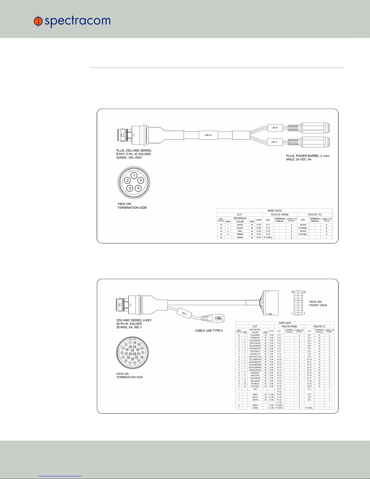
1.3 Included Cables
The VersaPNT Evaluation Kit contains the following cables (the antenna cable is not shown):
Power Cable
I/O Cable
1.3 Included Cables
CHAPTER 1•VersaPNT Getting Started Guide Rev. 2.0 7
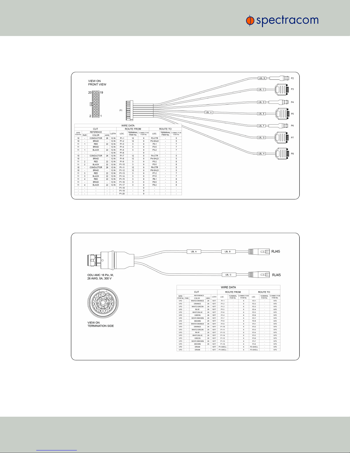
I/O Breakout Cable
Ethernet Data Cable
8CHAPTER 1•VersaPNT Getting Started Guide Rev. 2.0
1.3 Included Cables
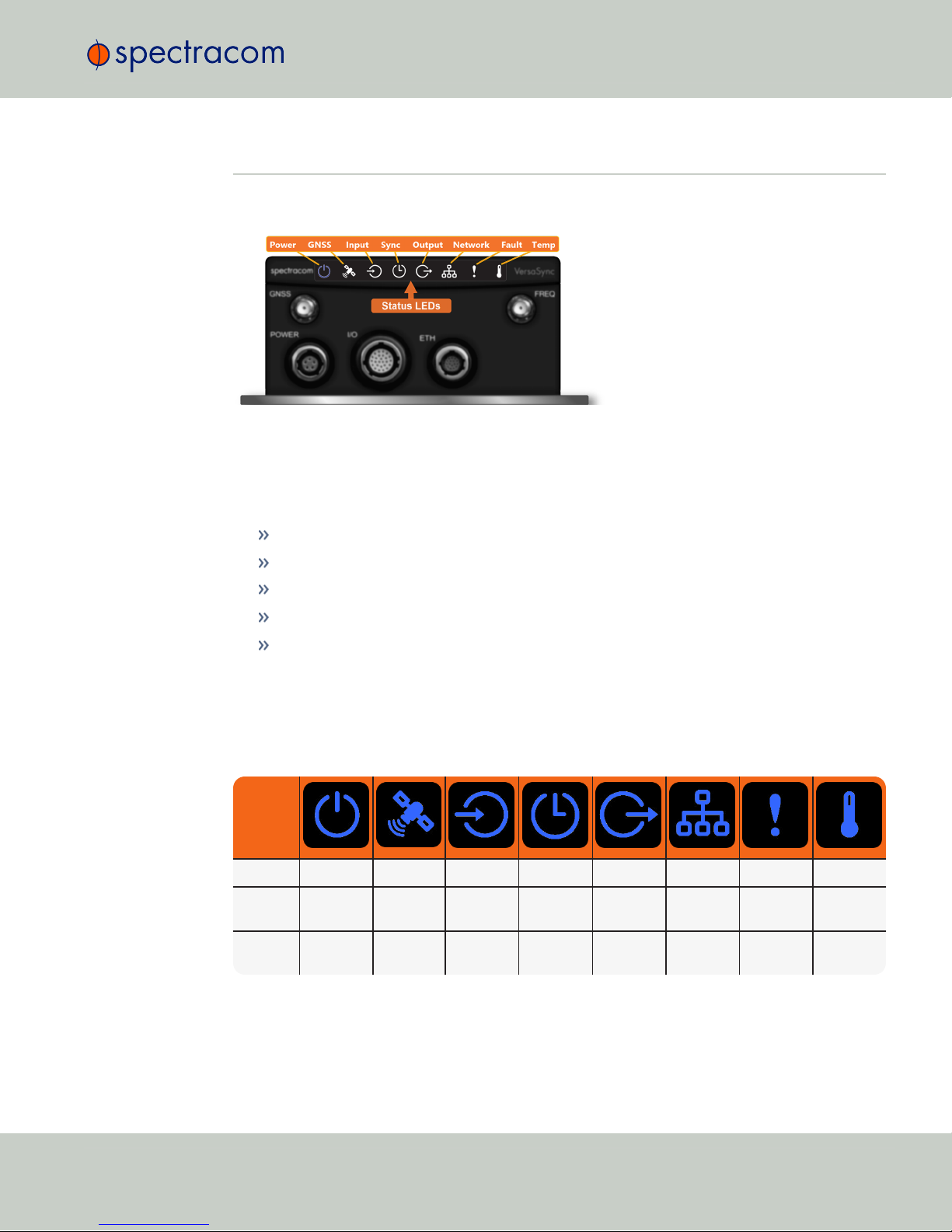
1.4 Status LEDs
VersaPNT's front panel status LEDs provide a real-time status overview: Eight (8) LEDs indicate
the unit's current operating state:
The LEDs can be disabled, see "Blackout Mode" on page11.
1.4.1 Blinking Intervals
The status LEDs can communicate five different operating states:
"OFF"
"ON"
"FAST": blinking interval @ 8Hz
"SLOW": blinking interval @ 2Hz
"HEARTBEAT": sinus-shaped interval @ 1Hz
1.4.2 LED Lighting Patterns
The table below indicates LED status light patterns for common VersaPNT operating statuses.
Table 1-7: Common light patterns
Start-up HEARTB. OFF OFF OFF OFF OFF OFF OFF
Acquir-
ing fix
FAST FAST FAST FAST FAST FAST HEARTB. FAST
Software
upgrade
FAST OFF OFF FAST OFF FAST HEARTB. OFF
1.4 Status LEDs
CHAPTER 1•VersaPNT Getting Started Guide Rev. 2.0 9
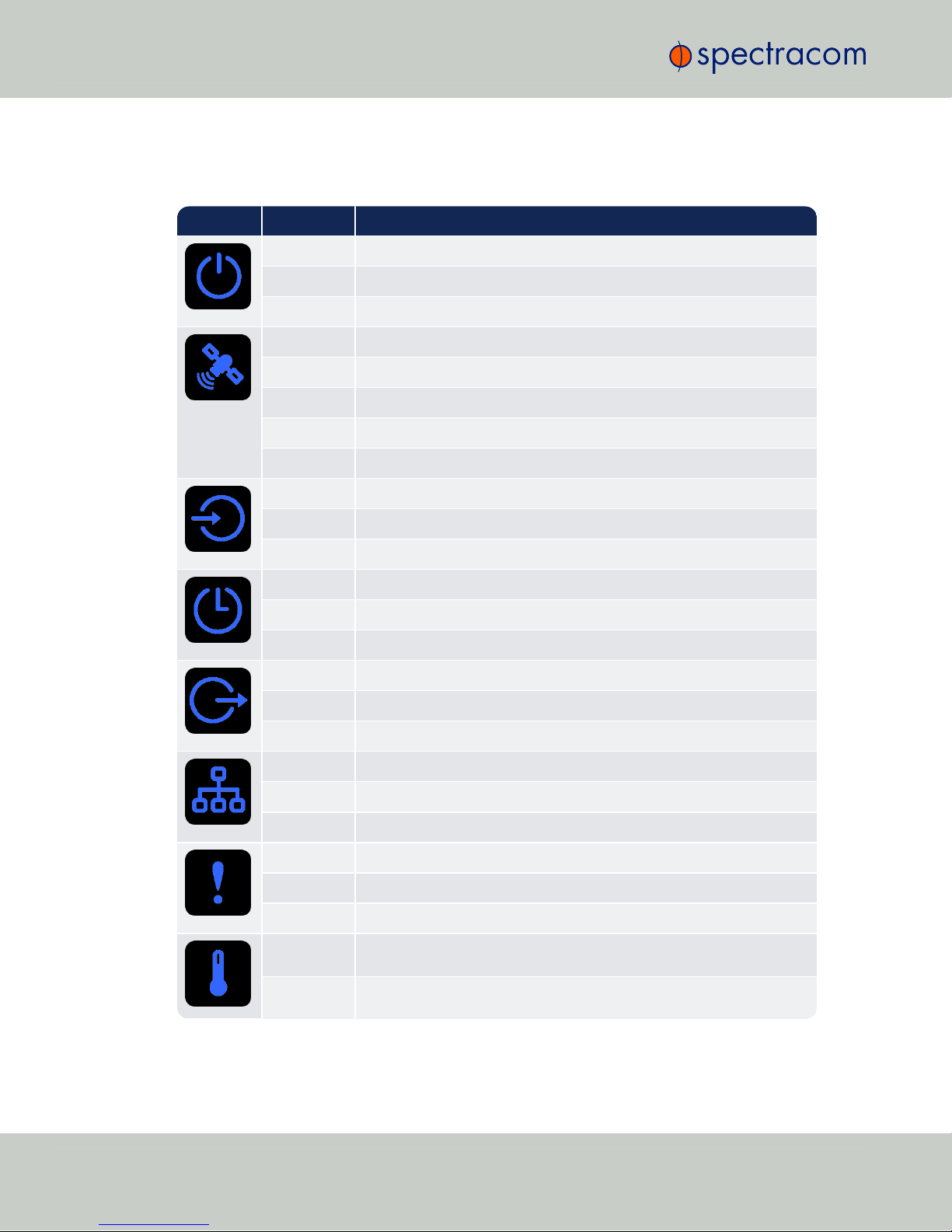
1.4.3 Legend, individual LEDs
Table 1-8: Legend for Status LEDs
Icon Light Meaning
OFF No power
HEARTBEAT Booting
ON Powered
OFF No GNSS reception (0 satellites)
HEARTBEAT GNSS acquisition in process (≥ 1satellite(s), or 1PPS OK, or Time OK
SLOW Jamming detected
FAST Antenna short circuit
ON GNSS is available as reference (1PPS and Time OK)
OFF Inputs not detected/all inputs are disabled
FAST 1 or more input is missing, or invalid timing on 1 or more input detected
ON Inputs are enabled
OFF Unit is in Holdover (valid)
ON System Clock OK (valid)
FAST Invalid Time (Holdover period exceeded, or oscillator damaged)
OFF No output signal(s) detected/all outputs are disabled
FAST Malfunction detected (short circuit, or overload)
ON Outputs are enabled
OFF No network detected
FAST Network malfunction detected (e.g., no auto-negotiation)
ON Network OK, configuration OK
OFF Unit OK
FAST Unit requires attention; check other status LEDs, see Web UI
HEARTBEAT See table "LED Lighting Patterns" on the previous page
OFF Temperature OK
FAST High temperature detected
10 CHAPTER 1•VersaPNT Getting Started Guide Rev. 2.0
1.4 Status LEDs
1.4.3.1 LED Patterns during Boot Sequence
For the first five seconds after power-up all LEDs will be OFF. Then the Power LED will be blink-
ing before it will be lit permanently. If you have configured your unit to operate in Blackout
Mode, this will take effect once the blinking cycle ends.
1.4.4 Blackout Mode
All LEDs can be turned off via the WebUI.
The LED brightness level can be set from 63 (as bright as possible) to 0(not visable).
To disable all LED activity via the WebUI:
Navigate to MANAGEMENT > OTHER: LED Configuration, and set the Brightness level to
"0".
1.5 The VersaPNT Web UI
VersaPNT has an integrated web user interface (referred to as "WebUI" throughout this doc-
umentation) that can be accessed from a computer over a network connection, using a standard
web browser. The WebUI is used to configure the unit, and for status monitoring during every-
day operation.
Note: An integrated Command-Line Interpreter interface (CLI) allows the use of a
subset of commands that are integrated into the Web UI.
The minimum browser requirements for the Web UI are: Internet Explorer ®9 or higher,
Firefox®, or Chrome®.
1.5.1 The Web UI HOME Screen
Note: Screens displayed in this manual are for illustrative purposes. Actual
screens may vary depending upon the configuration of your product.
The HOME screen of the VersaPNT web user interface ("Web UI") provides comprehensive
status information at a glance, including:
vital system information
current status of the references
key performance/accuracy data
major log events.
1.5 The VersaPNT Web UI
CHAPTER 1•VersaPNT Getting Started Guide Rev. 2.0 11

The HOMEscreen can be accessed from anywhere in the Web UI, using the HOMEbutton in
the Primary Navigation Bar:
The Primary Navigation Bar provides access to all menus:
HOME: Return to the HOME screen (see above)
INTERFACES: Access the configuration pages for …
… references (e.g., GNSS, NTP)
… outputs (e.g. 10 MHz, PPS, NTP) and
… installed input/output option cards.
MANAGEMENT: Access the NETWORK setup screens, and OTHER setup screens e.g., to
configure Reference Priorities, System Time, and the Oscillator.
TOOLS: Opens a drop-down menu for access to the system maintenance screens and sys-
tem logs.
HELP: Provides Spectracom Service Contact Information and high-level system con-
figurations you may be required to furnish when contacting Spectracom Service.
12 CHAPTER 1•VersaPNT Getting Started Guide Rev. 2.0
1.5 The VersaPNT Web UI

Quick Start
During the procedure described below, you will connect the Power cable, the Multi I/O cable,
and the Ethernet cable to the unit. These cables are included in the Evaluation kit. If you plan to
use your own cables, some of these instructions may not apply.
The step-by-step instructions below outline the VersaPNT installation and configuration process:
1. Install VersaPNT in the designated vehicle:
Choose a mounting location within reach of your antenna and networking cables
A location near the center of gravity of the vehicle is recommended.
It is recommended to orient the unit so that the rear panel of the unit (the opposite
of the connector face) points in the direction of travel. Other orientations (includ-
ing upside down) are possible, but will require Frame Rotation calculations (see
""Frame Rotation" Tab" on page33).
Ground the unit by connecting the DC negative terminals to the chassis of the unit,
and to the vehicle metallic structure.
The mounting plate should be in direct contact with the unit base plate, and the
mounting surface is even and heat conductive.
2. Install the GNSS antenna(s). Follow your antenna manufacturer's instructions. See ""Cal-
ibration" Tab/Antenna Installation" on page29 for specifications.
3. Wire the antenna cables and interface cables. (Most customers will require the Multi I/O
and Ethernet cables for these connections.)
USB: Connect the Multi I/O connector to the VersaPNT unit. If you are using the
Evaluation Kit, connect the Multi I/O USB output to a PC. Install a terminal emu-
lator program on the PC (e.g., TeraTerm®or PuTTY®).
Ethernet: Connect the Ethernet cable to the ETH port of the unit. If you are using
the Evaluation Kit, connect at least one of the two I/O cable Ethernet ports (ETH0
or ETH1) to a network switch/hub, or to the PC mentioned above (using a stand-
ard Ethernet patch cable, or a crossover cable).
Requirement Action Evaluation kit cable
USB con-
nection
Connect USB to the Multi I/O
connector.
Connect the USB connector to a PC with a terminal
emulator program (CA08R-CRUB-0002)
Network
connection
Connect at least one of the
two Ethernet connectors to a
network.
Connect the RJ45 jack labeled ETH0 or ETH1 to a
network hub/switch or directly to a PC (CA08R-
CRET-0002)
For pinout tables, see "Connectors and their Pinouts" on page4.
4. Connect the power supply. The unit will power up, and the ON/OFF status LED will
pulsate.
CHAPTER 2•VersaPNT Getting Started Guide Rev. 2.0 13
Requirement Action Evaluation kit cable
Power up Connect 12 VDC to the
power connector.
Attach a cable and apply 12 VDC to the plug labeled
"Main" (CA08R-CRPB-0002)
5. Establish a network connection so as to allow access to the web user interface ("Web UI").
See "Network Setup" below for information on the USB driver installation and network
address configuration.
Note: On a DHCP network, you can also use Zeroconf to access the Web
UI (see "Zero Configuration Setup" on page19).
6. Using the Web UI, configure the following:
Software-configurable I/O pins, see "Assigning I/O Pins" on page21.
INS settings, see "INS Configuration" on page26:
IMU data output settings (output format, position type, polling frequency)
Calibration settings: antenna offsets
Data log settings
FIR filter settings
Coning and sculling error compensation settings
Frame rotation configuration (if required).
This list covers the standard configuration options. More complex configurations
can be generated using the "INS Expert Mode" on page35.
Other VersaPNT INTERFACES settings and MANAGEMENT settings e.g., network
settings, reference priorities (see main product user manual).
2.1 Network Setup
After making the connections outlined in the Quick Start list, the following information will help
you to establish a network connection.
VersaPNT has a Command Line Interpreter ("CLI"). Using the CLI connection, you can set up
access to the web user interface ("Web UI") that is used to configure and monitor the unit.
Default settings:
VersaPNT network settings default to DHCP, i.e. if the unit is connected to a DHCP server via
ETH0 or ETH1, it will accept an assigned dynamic IP address.
14 CHAPTER 2•VersaPNT Getting Started Guide Rev. 2.0
2.1 Network Setup
In order to apply a static IP address, DHCP must be disabled. (Your network administrator can
provide you with an IP address you can use for the unit.)
Note: VersaPNT supports zeroconf: If you have a DHCP enabled network, you can
use zeroconf for initial setup. For more information, see "Zero Configuration
Setup" on page19. Otherwise follow the instructions below for conventional
setup.
Network connection:
1. USB Driver
On the PC connected to your unit, new hardware (the USB interface) will be detec-
ted. The correct driver should be installed automatically. If not, download the
driver from www.ftdichip.com/Drivers/VCP.htm, and install it manually via
the instructions for your operating system.
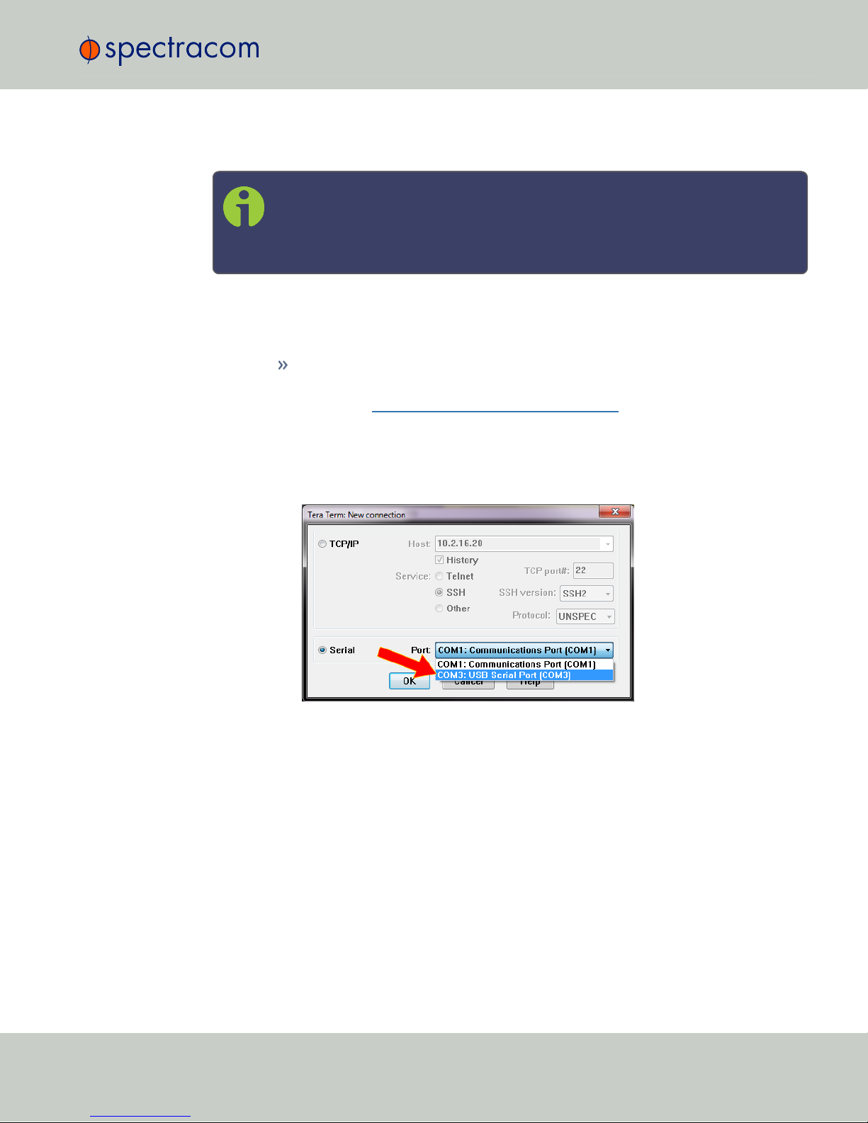
2. Network Address
a. Start the terminal emulator program on the PC. Select the COM port that is
assigned to the USB interface:
Access the CLI via ssh or telnet: The required port configuration is 115200 8N1:
2.1 Network Setup
CHAPTER 2•VersaPNT Getting Started Guide Rev. 2.0 15
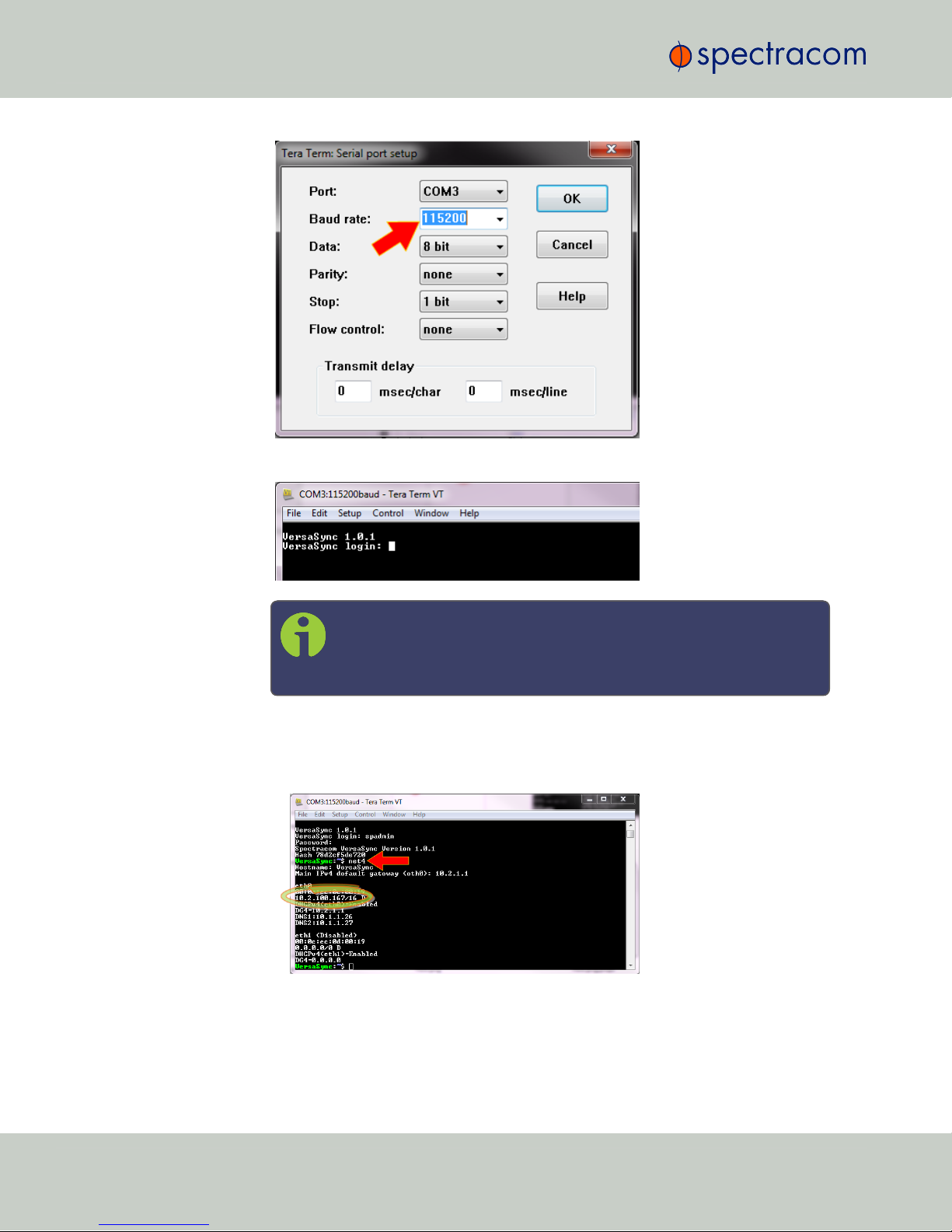
Press the Return key, and enter the login credentials:
Note: The default login credentials are:
User name =spadmin
Password =admin123 (will not be displayed on the screen)
b. If you are on a DHCP-enabled network, retrieve the IP address assigned to Ver-
saPNT by typing the net4 command. The command should return the network set-
tings, including the IP address assigned to the unit. Take note of the IP address.
You can use this IP address to login to the VersaPNT Web UI and then set a static
IP address, subnet mask and gateway (see Step 4. below).
16 CHAPTER 2•VersaPNT Getting Started Guide Rev. 2.0
2.1 Network Setup
Table of contents
Other Spectracom GPS manuals


