Copyright © SpectraDynamics, Inc. 2005 6
Description
The battery backup module allows the PD5-RM-B instrument to be powered by a 24
VDC power source in case of loss of the main AC power. The switch from AC to DC
supply operation is effected by a schottky diode network and charge storage capacitors
to ensure glitch free operation. The +24 VDC power source connector is located on the
back panel of the instrument. The +24 VDC ground is not connected to the instrument
case ground internally, however both ground connections are available at the DC power
connector and may be connected together at this point.
DC Voltage
The + 24 VDC may be used as backup power to prevent loss of signal during power
outages. The DC power supply should be able to provide 24VDC at 2A. For optimum
performance the following specifications should be used for the power supply.
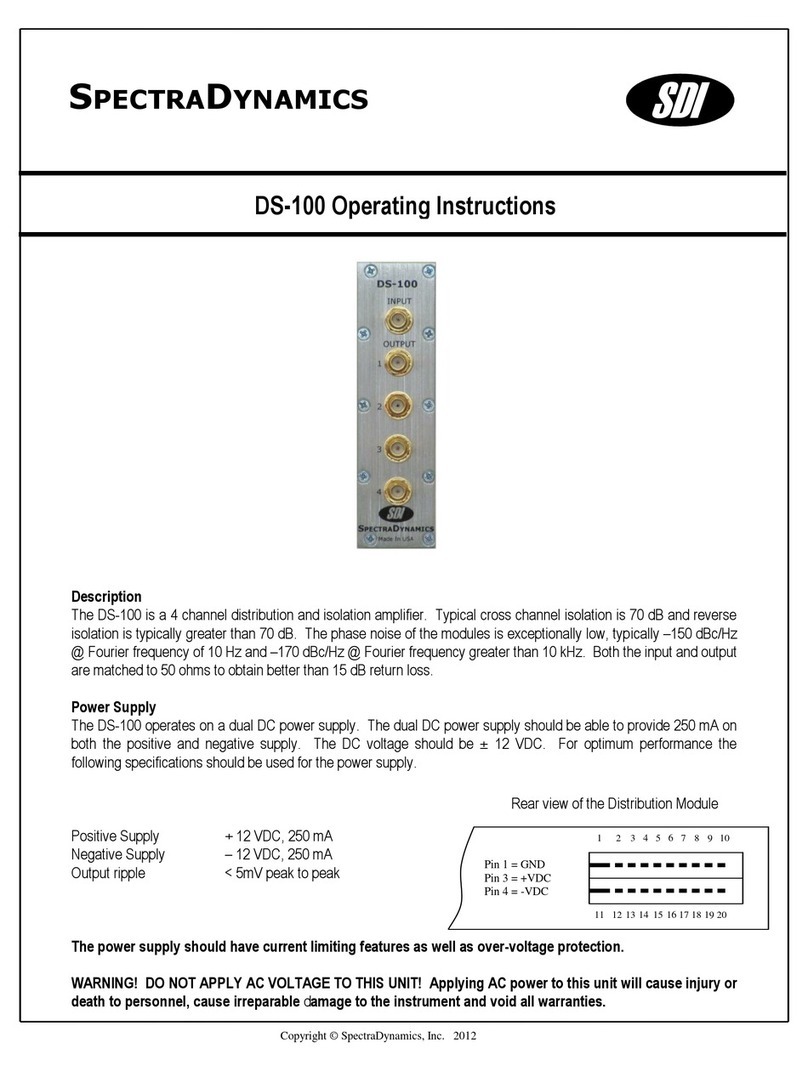
DC Supply 24 VDC, 2 A
Line regulation +/- 0.05% for a 10% line change
Load regulation +/- 0.05% for a 50% load change
Output ripple < 5mV peak to peak
DC Fuse 2A Slow blow
Fuse
A 2.0 Ampere 250V slow-blow fuse is used for +24 VDC operation.
Replace fuses with the same type and specifications.
Service
Do not attempt to service or adjust the instrument unless another person, capable of
providing first aid or resuscitation, is present. Contact SDI for any questions or repairs.
Operation
To operate the unit, locate the AC power entry connector on the rear panel and connect
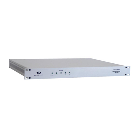
the power cable. When power is applied to the unit, a red led located on the front panel,
labeled “on”, should light up. Connection of the +24 VDC supply is optional. If the +24
VDC supply is connected a red led on the front panel labeled DC Power connector will
turn on.
Battery Backup Module
SDI
