SpectraDynamics FS-100RM-5 User manual
FS-100RM-5
LOW NOISE FREQUENCY MULTIPLIER
OPERATING MANUAL
SPECTRADYNAMICS, INC • 1849 Cherry St. Unit 2. • Louisville, CO 80027
Phone: (303) 665-1852 • Fax: (303) 604-6088
www.spectradynamics.com
SPECTRADYNAMICS, INC

FS-100RM-5, Low Noise Frequency Multiplier Operating Manual
Copyright © 2015 SpectraDynamics, Inc. All rights reserved.
FS-100RM-5:R00-2015/MD

Contents
1.0 Introduction …………………………………………………………………….... 1
2.0 Safety and preparation for use ………………………………..……….…….. 2
2.1 Electrical ……………….…………………………………………….……. 2
2.2 Instrument ……..…………….………………………………….….…….. 3
3.0 Front panel description …….…………………………………………….…… 4
4.0 Back panel description ………………………………………………….……. 5
5.0 Installation ……………………………………………………………….…….. 6
6.0 Operation ……………………………………………………………………… 7
7.0 Troubleshooting ………………………………………………………………. 8
8.0 Specifications …………………………………………………………………. 9
9.0 Warranty and service ………………………………………………………… 10


1.0 Introduction
Page 1
The FS-100RM-5 is an ultra-low noise frequency multiplier that takes an input signal
at 5 MHz. This versatile unit allows customers to select the output frequencies of choice at
the time of ordering. Available output frequencies are: 10, 20, 40, 80, 90 and 100 MHz.
The nominal output level of all output frequencies is +13 ±2 dBm. All outputs are
bandpass filtered to provide better than 50 dB of rejection for all spurious and harmonic
signals. The ultra-low residual phase noise of the multiplier allows it to be used with state-
of-the-art crystal frequency sources without degrading phase noise or environmental
stability.
The FS-100RM-5 is designed to be powered by a 100 to 240 VAC mains source and/or an
optional +12 to +36 VDC power source. If the instrument is acquired without the optional
battery back up module, the back panel will contain a black plastic cover instead of a DC
connector. When the unit contains a DC connector on the back panel, the user may power
the unit with both AC and DC power sources, in case of a loss of the main AC power the
instrument will automatically switch from AC to DC supply operation using a Schottky
diode network and charge storage capacitors to avoid any glitches and ensure
uninterrupted continuous operation.

2.0 Safety and Preparation for Use
Page 2
The FS-100RM-5 was designed for indoor use only and is not intended for operation
outdoors or in a wet environment. The instrument may be mounted in a standard 19-inch
instrumentation rack or may be used on a laboratory bench.
Inspect the instrument and power cords for damage before first use.
2.1 Electrical safety and preparation for use
Voltages capable of causing injury or death are present in this instrument. Use extreme
caution whenever the instrument cover is removed.
Line Voltage
This instrument is designed to operate on either 100 to 240VAC, 47 to 63 Hz AC and/or
+12 to +36 VDC at 1 Ampere power source.
Fuse
A 1.0 Ampere 250V slow-blow fuse is used for 100-240 VAC operation.
A 1.0 Ampere 250V slow-blow fuse is used for the DC power protection.
Only replace fuses with the same type and specifications.
AC Power
The instrument has a detachable three wire power cord for connection to a grounded AC
power source. The enclosure of the unit is directly connected to the outlet ground to protect
against electrical shock. Always use an outlet with a protective ground and do not disable
this safety mechanism. Detaching the AC power cord is the only option of disconnecting
the unit from the AC mains supply. Make sure you have access to the rear panel or provide
an external accessible AC disconnect means for your FS-100RM-5.
DC Power - Optional -
When the unit contains a DC connector on the back panel, the connector is configured as
follows:
Pin 1 NC
Pin 2 NC
Pin 3 NC
Pin 4 +12 to +36 VDC power return
Pin 5 +12 to +36 VDC power
Pin 6 Chassis GND /Earth GND

2.0 Safety and Preparation for Use
Page 3
Verify that the connector from your DC power supply has the pin configuration mentioned
on page 2. Do not apply AC voltage to the DC power connector. Failure to follow these
directions may cause injury or death to personnel, cause irreparable damage to the
instrument and voids all warranties.
If you provide DC power to your unit, detaching the DC power cord is the only option of
disconnecting the unit from the DC mains supply. Make sure you have access to the rear
panel or provide an external accessible DC disconnect means for your FS-100RM-5.
Please note that the power return (pin 4) is NOT connected to the instrument case ground
internally, however both ground connections (pin 4 and pin 6) are available at the DC
power connector and may be connected together at this point.
2.2 Instrument safety and preparation for use
Input RF Signals
The 5 MHz input signal level must be greater than +10 dBm, otherwise the multiplier will
not function properly and noise performance may be seriously degraded. The multiplier is
not a linear device therefore the output power does not vary linearly with input power. The
absolute maximum specifications should be observed to obtain the optimum performance
and ensure reliability.
Absolute Maximum Ratings
Input RF Power +20 dBm Maximum
Reverse RF Power +20 dBm Maximum
DC Voltage @ RF Input 20 VDC Maximum
DC Current @ RF Input 100 mA Maximum
DC Voltage @ RF Output 50 VDC Maximum
Storage Temperature -10 to +75 ºC
Operation Environment 0 to +50 ºC
Humidity 5% to 95% Non-condensing
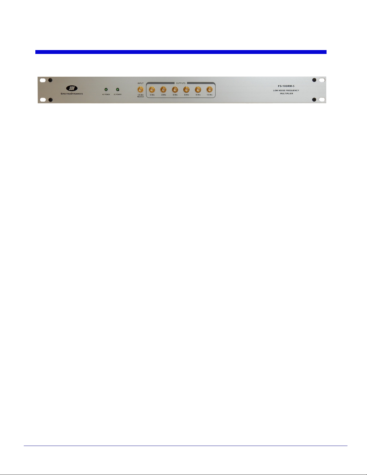
3.0 Front Panel
Page 4
AC Power
The AC Power LED turns on when AC power is applied to unit.
DC Power
The DC Power LED is on when DC power is applied to unit.
INPUT
A 5 MHz RF signal with a level greater than +10 dBm may be connected to the SMA
connector labeled INPUT.
OUTPUTS
This versatile unit allows customers to select the output frequencies of choice at time of
ordering. Available output frequencies are: 10, 20, 40, 80, 90 and 100 MHz.

4.0 Back Panel
Page 5
AC POWER
The FS-100RM-5 is configured to operate on 100 to 240 VAC.
DC POWER
If the instrument was acquired with the optional DC battery back up module, the unit may
operate on +12 to +36 VDC at 1 Ampere. When the FS-100RM-5 is set up to operate with
both AC and DC power sources at the same time the DC power is used as backup power
in case of AC power outages.

5.0 Installation
Page 6
Connecting power
The FS-100RM-5 ships with a standard North American or European IEC power cord. The
instrument may be mounted in a standard 19-inch instrument rack or may be operated on
a laboratory bench.
Locate the AC POWER entry module on the rear of the enclosure, connect the power cord
and turn on the power.
In the case that the FS-100RM-5 was acquired with the optional DC battery backup
module, you may locate the DC connector on the rear of the enclosure, connect the DC
power cord and turn on the power.

6.0 Operation
Page 7
Once power is supplied to the instrument and the instrument is turned on, the LED on the
front panel labeled AC will turn on. If you also apply the DC voltage the LED labeled DC
POWER on the front panel should light up. The 5 MHz input signal to be multiplied should
be connected to the SMA connector on the front panel labeled INPUT. The multiplied
signals will be available at the SMA connectors labeled OUTPUTS.

7.0 Troubleshooting
Page 8
Do not attempt to service or adjust the instrument unless another person, capable of
providing first aid or resuscitation, is present. If there are problems that cannot be
resolved by the troubleshooting steps below please contact technical support.
Technical Support
Tel: +1 (303) 665-1852 , Fax: +1 (303) 604-6088
support@spectradynamics.com, www.spectradynamics.com
AC Power LED does not turn on.
Disconnect the power cord. Check the main AC power fuse and power cord. If the fuse is
blown replace with same type and rating. Please contact SDI if the fuse blows again or if
the event that caused the fuse to blow is not known.
DC Power LED does not turn on.
Disconnect the power cord. Check the main DC power fuse and power cord. If the fuse is
blown replace with same type and rating. Please contact SDI if the fuse blows again or if
the event that caused the fuse to blow is not known.
No signal on the RF outputs.
Verify that the input signal frequency is 5 MHz +/- 250kHz, and that the amplitude of the
signal is greater than +10 dBm.

8.0 Specifications
Page 9
PARAMETER CONDITIONS MIN TYP MAX UNITS
Output Power +13 dBm input +10 +13 +15 dBm
Impedance input
output
50
50
Ohms
Return Loss
input(S11)
output(S22)
-15
-15
-20
-20
dB
Spurious Harmonics of input frequency -55 -45 dBc
Harmonic Distortion +13 dBm output
Harmonics of output frequency
-55
-45 dBc
Phase Noise
Referred to 5MHz
input
1 Hz
1 kHz
10 kHz
-143
-170
-176
-140
-167
-173
dBc/Hz
Temperature-delay
Coefficient
0 - 50 ºC
45
50 ps/ºC
All tests done at 5 MHz and +13 dBm input unless otherwise specified.

9.0 Warranty and Service
Page 10
Warranty
The FS-100RM-5 is warranted to be free of defects under normal operating conditions, as
specified, for one year from date of original shipment from SpectraDynamics, Inc. (SDI).
SDI’s obligation and liability under this warranty is expressly limited to repairing or
replacing, at SDI’s option, any product not meeting the said specifications. This warranty
shall be in effect for one (1) year from the date a FS-100RM-5 is sold by SDI. SDI makes
no other warranty, express or implied, and makes no warranty of the fitness for any
particular purpose. SDI’s obligation under this warranty shall not include any transportation
charges or costs of installation or any liability for direct, indirect, or consequential damages
or delay. Any improper use, operation beyond capacity, substitution of parts not approved
by SDI, or any alteration or repair by others in such manner as in SDI’s reasonable
judgement affects the product materially and adversely shall void this warranty. No
employee or representative of SDI is authorized to change this warranty in any way or
grant any other warranty.
Service
Do not attempt to service or adjust the instrument unless another person, capable of
providing first aid or resuscitation, is present. Please remember that any alteration or repair
may void the warranty. Contact SDI with any questions or to request an RMA if a repair is
needed.
SpectraDynamics, Inc.
1849 Cherry Street Unit 2.
Louisville, CO 80027
USA
Tel: (303) 665-1852
Fax: (303) 604-6088
support@spectradynamics.com
www.spectradynamics.com

Table of contents
Popular Network Hardware manuals by other brands

OpenEye
OpenEye OE-N4U16 user manual

ADTRAN
ADTRAN NetVanta E1/FE1 Network Interface Module quick start guide

Huawei
Huawei FIC-1E1 Specifications

Thales
Thales CipherTrust Manager k160 quick start guide

D-Link
D-Link DWL-2700AP - AirPremier Outdoor Wireless Access... Quick installation guide

Proscend
Proscend M366 user manual


Bosch
Bosch VIP X1600 Module Quick information guide

QNAP
QNAP VioStor-5000 Series user manual

Jinan USR IOT Technology
Jinan USR IOT Technology USR-TCP232-T instructions

TP-Link
TP-Link VIGI NVR11104H-4P user guide

Dahua
Dahua nvs0104dh quick start guide

ADTRAN
ADTRAN Total Access 300 Series Installation and maintenance guide