manuals.online logo
Brands
  1. Home
  2. •
  3. Brands
  4. •
  5. ADTRAN
  6. •
  7. Network Hardware
  8. •
  9. ADTRAN Total Access 300 Series User manual

ADTRAN Total Access 300 Series User manual

1
jobAid
DESCRIPTION
This Job Aid supports three Active Ethernet Single Family Unit (SFU) Optical
Network Terminal (ONTs) that can be installed in four different configurations
at the subscriber’s residence.
■Outdoor Installation, using ONT 1287704G1
■Indoor Installation in an unrestricted location, using ONT 1287704G1 and
Mounting Bracket 1187777G1
■Indoor Installation, using ONT 1287737G1
■Indoor Installation, using ONT 1287737G2
The following table lists the supported equipment.
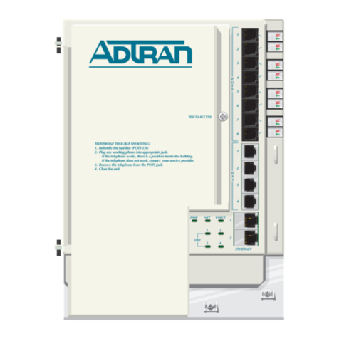
The following illustration is typical of an “Outdoor” ONT.
The illustration below is typical of an unrestricted access location ONT.
Description Part Number CLEI
Total Access 354E Active Ethernet SFU
ONT
1287704G1 BVMBD10F _ _
Total Access 324E Indoor Active Ether-
net ONT
1287737G1 BVMBE10F _ _
Total Access 324E Indoor Active Ether-
net ONT with UPS
1287737G2 BVMBF10F _ _
Total Access 3XX Mounting Bracket 1187777G1 NA
Surface
Mounting
Hole
Surface Mounting
Hole
Hinge
Hinge
Security
Screw
Two-screw
Terminal
Bridges
Ethernet
Connections
Fiber Optic
Cable
Ground
Power
Ethernet Drop
POTS Drop
Ground and
PowerDrop
Callout
Ground Drop
Fiber Drop
RING
TIP
RING
TIP
FXS 0/1
FXS 0/2
ETH 0/1
ETH 0/2
TIP RING
POTS 2
POTS 1
TELCO ACCESS
ETH 1 ETH 2
ETH 3
ETH 4
TOTAL ACCESS 354E
1287704G1
12V , 1.0A
POWER
NETWORK STATUS
TELEPHONE TROUBLESHOOTING
1.Identify the bad line.
2.Disconnect the plug from the appropriate POTS jack and plug
any working telephone into that jack.
If the telephone works, there is a problem inside the house.
If the telephone does not work, contact your service provider.
3.Remove the telephone and replace the plug into the POTS jack.
4.Close the unit.
CLEI
TEL.NUMBER
TIP/RING POTS 1
POTS 2
Total Access 300 Series
Active Ethernet
Single Family Unit ONT
NOTE
For installation in an Unrestricted Access location, refer to the Total Access 300
Series Active Ethernet Single Family Unit ONT Installation and Maintenance Guide
(P/N 612877AEONT-5).
The illustration below is typical of an “Indoor” ONT. The difference between
the two versions of the Total Access 324E ONT is the power source. Part
number 1287737G1 uses a 3-pin 12 Volt AC Adaptor, and the 1287737G2 uses
an Uninterruptible Power Source (UPS). The following illustration represents
the 1287737G2.
TIP/RING
Ground Wire
DO NOT Use Terminal Bridges for POTS Connections.
TELCO ACCESS
ETH 1 ETH 2
TOTAL ACCESS 354E
1287704G1
12V , 1.5A
POWER
NETWORK STATUS
TELEPHONE TROUBLESHOOTING
1. Identify the bad line.
2. Disconnect the plug from the appropriate POTSjack and plug
any working telephone into that jack.
If the telephone works, there is a problem inside the house.
If the telephone does not work, contact your service provider.
3. Remove the telephone and replace the plug into the POTSjack.
4. Close the unit.
CLEI
TEL. NUMBER
POTS 1
POTS 2
POTS 1
POTS 2
ETH 3 ETH 4
TIP/RING
Tie Wrap Point
Power
Tie Wrap Point
Fiber
PHONE 1 PHONE 2
NET
123
ETHERNET
4
LOW BAT
BAT MIS
REP BAT
ON BAT
SIG RET
12V RET
+12V
Total Access 324E
PHONE
PWR NET 121234
ETH
Issue Date: March 2015
Document P/N: 612877AEONT-22B
The following related online documents and resources provide additional information for this product:
Total Access 300 Series Active Ethernet Single Family Unit Installation and Maintenance Guide
Total Access 5000 Series Fiber to the Premises Deployment Guide
Total Access 5000/5006 Engineering Guide
Documentation for ADTRAN Carrier Networks products is
available for viewing and download directly from the
ADTRAN Support Community website.
Go to: https://supportforums.adtran.com/welcome
Registration is required.
ADTRAN offers training courses on our products, including
customized training and courses taught at our facilities or at
customer sites.
For inquiries, go to: http://adtran.com/training
2612877AEONT-22B
INSTALLATION OUTDOORS
Mounting the ONT
CAUTION
!
■This equipment must be connected to a known, reliable earth ground at all
times during installation and service. Refer to the National Electrical Code
(NEC) and state/local codes for details on grounding requirements. A 6
AWG copper ground conductor shall be used to connect the equipment to
earth ground.
■This equipment must be serviced by authorized service personnel only. All
repair procedures are detailed to allow sub-assembly level repairs ONLY.
Authorized service personnel should not attempt component level repairs
or circuit modifications to the printed circuit board. Improper repairs can
create a safety hazard.
Complete the following steps to mount the enclosure:
1. Choose a vertical surface near an approved ground, but away from
down spouts, permanent water sprinklers, or other water sources. The
subscriber should have easy access for testing.
2. Use the top and bottom external mounting holes as a template to mark
fastener locations. Use a level to ensure the unit is level to prevent
warping.
3. Pre-drill the marked locations and install fasteners or anchors
appropriate to the mounting surface (each anchor rated to 15 lbs
minimum).
4. Mount the ONT to the side of the subscriber’s premise.
The Electronics Module is installed in the housing and swings open on hinges.
To release this module, loosen the Security Screw (refer to the illustration on
the first page) and swing the electronics Module to the left.
CAUTION
!
Do not use a knife to cut the opening in the rubber grommets. This may result
in an excessively large hole and compromise the integrity of the unit allowing
moisture into the unit.
Grounding the ONT
Install the ground connection by completing the following steps:
1. Remove the rubber grommet from the housing and insert a #6 solid cop-
per ground wire through the rubber grommet.
2. Using the figure on page 3, route the ground wire as shown and attach it
to the ground bar.
3. Replace the rubber grommet in the housing.
4. Route the ground wire 12 inches below finished grade by the shortest
and most direct route to the AC power ground system Multi Grounded
Neutral (MGN) of the customer premises. Ensure the wire is free of any
sharp bends.
5. Attach the ground wire to the side of the subscriber’s premises with
stainless steel half moon clamps or tie-wrap the ground wire to the riser
conduit of the Buried Fiber Drop.
6. Clean the MGN connector with emery cloth to insure a stable
connection.
7. Coat the connection with a metal corrosion preventative.
8. Attach the ground wire from the ONT to the MGN connector with the
appropriate UL approved ground clamp/fitting.
9. Attach a Warning Ground Tag to this grounding connection.
123
ACTIVE ETHERNET
Active Ethernet uses Ethernet components that are 802.3ah compliant. Active
Ethernet provides dedicated bandwidth based on individual subscriber
requirements that are applicable to both residential and business applications.
Because Active Ethernet is pure IP, no transition protocol is required.
The ONT and OLT employ bi-directional Small Form-factor Pluggable (SFP)
connectors for data transmission. To allow for transmission of downstream
and upstream traffic on a single fiber, different wavelengths are used for each
direction. Downstream traffic uses 1490 nm, while Upstream traffic uses 1310
nm. Refer to the Total Access 300 Series Active Ethernet Single Family Unit ONT
Installation and Maintenance Guide (P/N 612877AEONT-5). Section 2 contains
instructions for installing SFPs for Indoor ONTs, and Section 3 and 4 contain
instructions for installing SFPs for Outdoor ONTs.
INSTALLATION OVERVIEW
After unpacking the ONT, inspect it for damage. If damage is noted, file a
claim with the carrier and then contact ADTRAN. For more information, refer
to the warranty.
Installing the ONT includes the following:
■Installation Outdoors
♦Mounting the ONT
♦Grounding the ONT
♦Connecting Power/Alarms
♦Routing OptiTap Fiber
♦Installing SC/ACP Optical Connections
♦Connecting Local Power Source
♦Connecting POTS
♦Connecting Ethernet
■Installation Indoors
♦Connecting POTS
♦Connecting Ethernet
NOTE
The Total Access 300 Series Active Ethernet Single Family Unit ONT Installation
and Maintenance Guide (P/N 612877AEONT-5) contains all the information
necessary to install, test, and troubleshoot the ONTs represented in this Job
Aid.
Required Tools and Supplies
Standard technician tools and those listed below are required for installing the
ONT:
■Carpenter’s level
■3/32” screw driver for connecting ONT power
■5/32” hex tamper proof bit
■RJ-45/RJ-11 crimper
■A telephony/data communication test set
■PON power meter with wavelength filtering
■Fiberscope or videoscope
■Two #10 screws and appropriate surface anchors for mounting the ONT
■Assorted tie wraps for securing cabling and wiring
■Four RJ-45 plugs
■Two RJ-11 plugs (when not using two-screw terminal bridges)
For fiber optic connections, the following are required:
■Fiber Optical Fusion Splice Tools
■ODC Fiber optics cleaning tool
■SC/APC fiber connector
Included with the ONT packaging are 2 two-screw terminal bridges, fiber cable
management and strain relief, a fiber connector, and electronics/optics. For
data, the connection to the SFU is through the RJ-45 Ethernet connectors. For
POTS, the connection is made through two-screw terminal bridges, or RJ-11
connections.
612877AEONT-22B 3
Connecting Power/Alarms
NOTE
Wiring the Power/Alarm connector improperly could damage the ONT.
The ONT is supplied with a 7-conductor Power/Alarm connector. To make
connections from the UPS to the power connector refer to the illustration on the
next page and complete the steps below:
1. Remove the Power/Alarm Connector by pulling it out of the electronics
module.
2. Refer to the illustrations on the following page and the “Local Power
Source Wiring” section to assist in completing the next steps.
3. Remove the rubber grommet from the housing and insert the power and
ground cable through the grommet.
4. Terminate the two UPS power leads (Pins 6 and 7) and, if needed, the
five alarm status leads in the power connector.
5. Reconnect the Power/Alarm Connector to the bottom of the Electronics
Module.
6. Tie Wrap the wires through the holes just below the Power/Alarm
connector.
7. Replace the rubber grommet while closing the Electronics Module. This
places less stress on the wiring and allows the Electronics Module to
close without pinching any wiring.
Routing OptiTap Fiber Drop
Refer to the illustration below for OptiTap installation:
1. Place the OptiTap fiber drop in the same rubber grommet channel as the
ground cable. The ground cable should be “behind” the OptiTap fiber.
2. Place the OptiTap connector in the cut-out in the housing.
3. Insert the LC SFP into the SFP cage on the Electronics Module. Ensure
the latch handle on the SFP is facing upward, and slide the SFP all the
way into the SFP cage until there is an audible “click”.
4. Install the optical connection between the SFP and the OptiTap
connector as illustrated below.
5. Route the cable so that when the Electronics Module is closed, the fiber
is not pinched.
+ 12VDC
12V RTN
SIG RTN
ON BAT
REP BAT
BATMIS
LOW BAT
7654321
+ 12VDC
12V RTN
SIG RTN
ON BAT
REP BAT
BAT MIS
LOW BAT
7654321
Power/Alarm
Connector
Back of Electronics Module
Fiber Optic Cable
Fiber Cable
SFP Optics
Connection
CAUTION
!
Ensure the fiber is free of crimps or excessive bends, and will not be pinched
when the Electronics Module is closed. There are wire routing clips on the
lower right of the Electronics Module housing. It is recommended that these
not be used.
Installing SC/APC Optical Connections
Refer to the Total Access 300 Series Active Ethernet Single Family Unit ONT Instal-
lation and Maintenance Guide (P/N 612877AEONT-5) for complete information
on installing the SC/APC optical connection using the bulkhead adaptor.
NOTE
For the optical connection without using the OptiTap, refer to the Total Access
300 Series Active Ethernet Single Family Unit ONT Installation and Maintenance
Guide (P/N 612877AEONT-5).
Connecting Local Power Source
Installation of the Local Power Source (LPS) will be dictated by on-site condi-
tions and local telephone company practices. Refer to the Total Access 300 Series
Active Ethernet Single Family Unit ONT Installation and Maintenance Guide (P/N
612877AEONT-5) for complete information on connecting to the LPS.
WARNING
!
■Before making any power connections to this equipment, verify the power
is off (fuse removed/breaker tripped).
■The ONT needs to be powered by a UL Listed Power Supply suitable for
the application with Output at LPS Levels.
CAUTION
!
To reduce the risk of fire, use minimum no. 26 AWG telecommunications line
cord.
NOTE
This equipment should only be operated from the type of certified/listed
power supply recommended by the manufacturer.
Connecting POTS
The telephone service or POTS connections can be made with either two-screw
terminal bridges, or RJ-11 connectors.
If the two-screw terminal bridges are used the RJ-11 jacks provide a diagnostic
test point. Inserting an RJ-11 jack (i.e., telephone cable or telephone test set) will
connect the telephone set to the ONT and also disconnect the subscriber service
from the ONT providing fault isolation to the SFU or premises wiring.
To terminate the POTS lines on the two-screw terminal bridges complete the
following:
1. Trim each wire to length and strip insulation. Identify each pair in the
service cable.
2. Loosen the screws from the TIP (green) and RING (red).
3. Wrap the appropriate wire around the appropriate screw and tighten
the screws to secure the connections.

POTS can also be connected directly to the RJ-11 jack. In this case the two-
screw terminal bridges become isolated and are not used.
Connecting Ethernet
If the ONT is going to support 1 Gigabit operation (10/100/1000Base-T), the
cable used should be rated CAT 5e or better. Strip back the jacket of the
subscriber Ethernet cable and connect the 4-pair twisted wires to the RJ-45 Plug
using an RJ-45 crimper. Insert the terminated RJ-45 jack into the appropriate
RJ-45 ETH socket on the ONT.
Warranty: ADTRAN will replace or repair this product within the warranty period if it does not
meet its published specifications or fails while in service. Warranty information can
be found online at www.adtran.com/warranty.
©2015 ADTRAN, Inc. All Rights Reserved. *612877AEONT-22B*
INSTALLATION INDOORS
Refer to the following steps to install the ONT indoors:
1. Decide on a location for the ONT. Mount below eye-level so the LEDs
are visible.
2. Attach a 3/4” mounting board (typically plywood) to the wall. If the
wall is of drywall construction, ensure the mounting board is supported
by the wall studs.
3. Install two #8 Pan Head screws (1” or greater in length) approximately
5” apart. Use the two key holes on the back of ONT as location marks.
Leave approximately 1/4” protruding from the mounting surface.
4. Slide the ONT over the Pan Head screws and exert a small amount of
downward pressure to ensure that the top of the slots are resting on the
shafts of the pan head screws.
Connecting POTS
If POTS cables are not available, use the following procedure to create the
POTS cables:
1. Trim the insulation for the subscriber POTS cables.
2. Connect the twisted pair Tip (green) and Ring (Red) to the RJ-11
connector using an RJ-11 Crimper.
3. Insert the RJ-11 connector in the appropriate PHONE 1 or PHONE 2
jack.
Connecting Ethernet
The SFU ONT supports four 1 Gigabit (10/100/1000Base-T) connections. Use

CAT 5e, or better rated cables. If Ethernet cables are not available, use the
following procedure and table to create the Ethernet cables:
1. Trim the insulation for the subscriber Ethernet cable.
2. Connect the wires per the following table using an RJ-45 Crimper.
SFP Installation
Refer to Section 2 in the Total Access 300 Series Active Ethernet Single Family
Unit ONT Installation and Maintenance Guide (P/N 612877AEONT-5) for
instructions on installing the SFP for this ONT.
Ethernet RJ-45 Pin-out
Pin Name Description Color Code
1 TRD0+ Transmit/Receive Positive White/Orange
2 TRD0- Transmit/Receive Negative Orange
3 TRD1+ Transmit/Receive Positive White/Green
4 TRD2+ Transmit/Receive Positive Blue
5 TRD2- Transmit/Receive Negative White/Blue
6 TRD1- Transmit/Receive Negative Green
7 TRD3+ Transmit/Receive Positive White/Brown
8 TRD3- Transmit/Receive Negative Brown
PHONE 1 PHONE 2 NET
123
ETHERNET
4
LOW BAT
BAT MIS
REP BAT
ON BAT
SIG RET
12V RET
+12V
LED STATUS
The following LED table provides the LED status for both Outdoor and Indoor
ONTs.
OPERATIONAL SPECIFICATIONS
Refer to the Total Access 300 Series Active Ethernet Single Family Unit ONT Instal-
lation and Maintenance Guide (P/N 612877AEONT-5) for a list of all specifica-
tions for both the Indoor and Outdoor ONT.
■Voltage: 12Voltstypical
♦Minimum Voltage: 10 Volts
♦Maximum Voltage: 13.9 Volts
■Power Consumption:
♦Total Access 354E: 5.71 Watts
♦Total Access 324E: 6.42 Watts
♦Total Access 324E with UPS: 6.42 Watts
■Weight: 3.5 Pounds (NID and Electronics Module combined)
♦NID Outdoor Housing: 2.25 pounds (1 kilograms)
♦Electronics Module: 1.25 pounds(0.6 kilograms)
♦Indoor Module: 1.5 pounds (0.7 kilogram)
MAINTENANCE
Neither the Indoor or Outdoor ONT require routine hardware maintenance for
normal operation. ADTRAN does not recommend that repairs be attempted in
the field. Repair services may be obtained by returning the defective unit to
ADTRAN. Refer to the warranty for further information. Field support for
software is provided through upgrade facilities.
SAFETY AND REGULATORY COMPLIANCE
Refer to the appropriate Safety and Regulatory Compliance Notice
(61287737G1-17, 61287737G2-17 or 61287704G1-17) for detailed safety and
regulatory information.
Label Status Description
POWER 

Off
Green
No power
Power is On
NETWORK
STATUS



Green
Yellow
Red
OLT has activated the ONT
OLT is discovering and ranging the
ONT
OLT has shutdown the ONT
POTS 1 - 2 

2
Off
Green
Green Flashing
Administratively Shut Down
Off Hook
Ringing
ETH 1 - 4 

4
Off
Green
Yellow Flashing
Link is down: no activity or Adminis-
tratively Shut Down
10/100/1000 Link is up
TX or RX activity
C A U T I O N
C A U T I O N
!
SUBJECT TO ELECTROSTATIC DAMAGE
OR DECREASE IN RELIABILITY.
HANDLING PRECAUTIONS REQUIRED.
ADTRAN CUSTOMER CARE:
From within the U.S. 1.800.726.8663
From outside the U.S. +1 256.963.8716
PRICING AND AVAILABILITY 1.800.827.0807

Other manuals for Total Access 300 Series

11

Other ADTRAN Network Hardware manuals

ADTRAN 24-Port DSLAM Access Module IADSL Module User manual

ADTRAN

ADTRAN 24-Port DSLAM Access Module IADSL Module User manual

ADTRAN NetVanta 900 Series Manual

ADTRAN

ADTRAN NetVanta 900 Series Manual

ADTRAN Total Access SHDSL LTU Instruction Manual

ADTRAN

ADTRAN Total Access SHDSL LTU Instruction Manual

ADTRAN Total Access 300 Series User manual

ADTRAN

ADTRAN Total Access 300 Series User manual

ADTRAN XFP NG-PON2 ONU User manual

ADTRAN

ADTRAN XFP NG-PON2 ONU User manual

ADTRAN TRACER 4102 User guide

ADTRAN

ADTRAN TRACER 4102 User guide

ADTRAN ESU LT User manual

ADTRAN

ADTRAN ESU LT User manual

ADTRAN Cable T1 ESF CSU ACE User manual

ADTRAN

ADTRAN Cable T1 ESF CSU ACE User manual

ADTRAN 4202023L1 User manual

ADTRAN

ADTRAN 4202023L1 User manual

ADTRAN Stub Routing User manual

ADTRAN

ADTRAN Stub Routing User manual

ADTRAN T1 Nx64 HTU-R Instruction Manual

ADTRAN

ADTRAN T1 Nx64 HTU-R Instruction Manual

ADTRAN DS3 MX User manual

ADTRAN

ADTRAN DS3 MX User manual

ADTRAN Total Access 374 Product manual

ADTRAN

ADTRAN Total Access 374 Product manual

ADTRAN E1 User manual

ADTRAN

ADTRAN E1 User manual

ADTRAN DDS T200 Instruction Manual

ADTRAN

ADTRAN DDS T200 Instruction Manual

ADTRAN U-BR1TE Maintenance and service guide

ADTRAN

ADTRAN U-BR1TE Maintenance and service guide

ADTRAN Total Access Octal ADSL User manual

ADTRAN

ADTRAN Total Access Octal ADSL User manual

ADTRAN MX2800 STS-1 User guide

ADTRAN

ADTRAN MX2800 STS-1 User guide

ADTRAN NetVanta Series User manual

ADTRAN

ADTRAN NetVanta Series User manual

ADTRAN D4-n x 56 DSU DP User manual

ADTRAN

ADTRAN D4-n x 56 DSU DP User manual

ADTRAN SDX 611 GPON SFU ONT User manual

ADTRAN

ADTRAN SDX 611 GPON SFU ONT User manual

ADTRAN Total Reach DDS-DP 5 Series Instruction Manual

ADTRAN

ADTRAN Total Reach DDS-DP 5 Series Instruction Manual

ADTRAN 6540 Instruction Manual

ADTRAN

ADTRAN 6540 Instruction Manual

ADTRAN ENHANCED PSD 239 H2R User manual

ADTRAN

ADTRAN ENHANCED PSD 239 H2R User manual

Popular Network Hardware manuals by other brands

Bosch D8125INV Operation and installation guide

Bosch

Bosch D8125INV Operation and installation guide

ACTi GNR -3000 user manual

ACTi

ACTi GNR -3000 user manual

Cabletron Systems DLE52-MA user guide

Cabletron Systems

Cabletron Systems DLE52-MA user guide

BuildingLink KeyLink 140 PRODUCT SPECIFICATIONS & SETUP GUIDE

BuildingLink

BuildingLink KeyLink 140 PRODUCT SPECIFICATIONS & SETUP GUIDE

pivotal COMMWARE ECHO 5G How to set up

pivotal

pivotal COMMWARE ECHO 5G How to set up

VC 16835 Mounting and operating manual

VC

VC 16835 Mounting and operating manual

Barefoot nbn HFC Connection guide

Barefoot

Barefoot nbn HFC Connection guide

Juniper JATP700 Hardware guide

Juniper

Juniper JATP700 Hardware guide

Adva FSP 3000R7 Maintenance and troubleshooting manual

Adva

Adva FSP 3000R7 Maintenance and troubleshooting manual

ZyXEL Communications NSA-220 Plus user guide

ZyXEL Communications

ZyXEL Communications NSA-220 Plus user guide

Hoymiles DTU-Lite-S(Wi-Fi) Quick installation guide

Hoymiles

Hoymiles DTU-Lite-S(Wi-Fi) Quick installation guide

NETGEAR ReadyDATA 5200 installation guide

NETGEAR

NETGEAR ReadyDATA 5200 installation guide

Enterasys 6E2xx Local Management User’s Guide

Enterasys

Enterasys 6E2xx Local Management User’s Guide

Canon Vb-C60 - Ptz Network Camera Operation guide

Canon

Canon Vb-C60 - Ptz Network Camera Operation guide

LAPP ETHERLINE GUARD PM03T operating instructions

LAPP

LAPP ETHERLINE GUARD PM03T operating instructions

Gigamon GigaVUE H Series Hardware installation guide

Gigamon

Gigamon GigaVUE H Series Hardware installation guide

SonicWALL TELE3 TZ Getting started guide

SonicWALL

SonicWALL TELE3 TZ Getting started guide

AK-NORD COMPOINT-LIB manual

AK-NORD

AK-NORD COMPOINT-LIB manual

manuals.online logo
manuals.online logoBrands
  • About & Mission
  • Contact us
  • Privacy Policy
  • Terms and Conditions

Copyright 2025 Manuals.Online. All Rights Reserved.