Spectral ISOPOLE User manual

1-Insert the lower decoupling cone (the one with the brand name)into the mast
measuring the distance h2from the topof the mast. Insert the polyethelyne disc
into the cone fom the bottom of the mast to be centered.Adjust the clamp
Remove paint, oxid or anodized (if aluminum) and apply silicon grease to insure
a good electrical contactbetween the mast and the decoupling cones.
2-Insert the polyethelyne disc and after insert the cone and repeat the operation as in
the lowercone measuring the distance h1from the top of the mast.Both cones must be
placed with sheet metal unions simmetrically.
3-Pass the transmission lin RG-8or RG213 with the PL 259 through the mast and attach
to the recessed connector of upper radiator tigthening with hands.
4-Place the upper radiator base sleeve into the mast and tighten the three screw set.
Insert the rod into the upper radiator and measure the distance h3 from the base of the
lower decoupling.cone and secure the joint with the small clamp provided .
NOTE:The SpectralIsopole 144 is easy to tune simply by following the dimensions
provided with the tuning chart. If an SWR meter is available and it is desidered to tune
to the exact frequency, simply extend the dimension h3 between the upper radiator
and the upper cone equally to decrease the frequency of resonanace, and decrease
the distance h3 to increase the frequency of resonance.The lower cone must conserve
always the same distance to the upper cone: 65cm or 25-1/2 in.
SPECIAL RECOMMENDATIONS
*Never turn the upper radiator. Internal parts can be broken.
*Never use pliers or force tools to adjust the connector. This procedure must be
performed with hands.
*Neverhold the antenna withhands or ropestaking it fromthe radiator.Perform
this operation taking it from the bas of the connector or from under the clamp
of the upper cone.
*Adjust the decoupling cones clamps with a reasonable torque. A poor electrical
contact between the mast and the cones can cause noise and a poor performance
of the antenna
Technical support on line: [email protected]
Warning
*The antenna should be mounted so as clear sorrounding objects as much as possible,
a high location is desiderable.Be sure to muount the antenna so it will neither touch
or be able to fall with power wiring.
SPECTRAL IsoPole
VHF 144
The SPECTRALIsoPoleis a Hi-Quality product and has been designed to ofer the maximum performance for the application
required.It must be mounted in a metal mast of at least 22 mm (7/8")of internal diameter, to pass a PL-259 connector,and
no more than 32 mm (1.25")of external diameter The minimun mast length is3 meter(10 feet) for amateur frequencies .
INSTRUCTIONS ASSEMBLY (Use gloves to avoid metal cuts)
Visit our website: www.isopole.com or contact us: [email protected]
Amateur Frequency Chart
Mhz h1 h2 h3
144 to 148 1,27 1,92 2,54
* 50 75-1/2 100
Dimensions expressed in meters
*Dimensions expressed in inches
Specification or changes without previous notice
or obligation . 2000 SPECTRAL
HandcrafHandcraf
HandcrafHandcraf
Handcrafted in America!ted in America!
ted in America!ted in America!
ted in America!

SPECTRAL 01/W UHF
INSTRUCCIONES PARA EL ARMADO
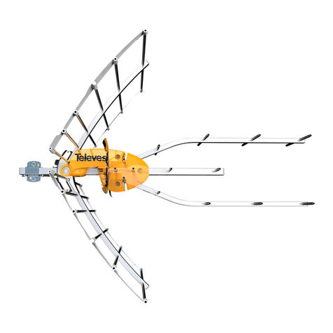
La Antena Spectral 01/W UHF representa un concepto diferente en Sistemas Irradiantes Verticales
Omnidireccionales, para estaciones de base, ofreciendo características excepcionalmente superiores a otras
antenas de este tipo tales como: ángulo de radiación 0º lo que posibilita la máxima ganancia en el horizonte con
un factor de dispersión uniforme a 360º, construcción extremadamente robusta capaz de soportar condiciones
meteorológicas duras, libre de mantenimiento y gran potencia admisible.
Diseñada para ser montada en un tubo de hasta 32 mm de diámetro exterior y un diámetro interior
suficiente para el paso de un conector de tipo N. Solamente se requiere el ajuste de los tres tornillos de la base
para la sujección al mástil.
AJUSTE
La Antena Spectral 01/W UHF se entrega pre ajustada, la operación de
ajuste final es muy simple; solamente es necesario variar la posición de los conos
de acuerdo a la tabla de dimensiones y frecuencias para obtener una sintonía
adecuada a la frecuencia a utilizar; por lo cual si se desea aumentar la frecuencia
de resonancia el cono superior deberá acercarse al aislador central y la operación
a la inversa, o sea separando el cono del aislador central si se desea disminuir la
frecuencia de resonancia de la antena. Es muy importante que cada vez que se
modifique la distancia del cono superior para variar la frecuencia de resonancia
de la antena, el cono inferior acompañe al superior, debiendo Siempreconservar
la misma distancia h2 entre uno y el otro.
* La medida debe ser tomada desde el centro del aislador central.
** La medida entre el cono superior e inferior debe permanecer constante.
Atención:
*La antena debe ser montada en un lugar abierto, sin objetos cercanos, o tan lejos como
sea posible; un lugar alto es apropiado.
*Asegúrese que la Antena no esté en contacto con cables de electricidad, líneas de alta
tensiónocablestelefónicos.Sidurantelainstalaciónéstacayerasobrelíneasdecorriente
eléctrica NO toque la Antena y recurra a la compañía de electricidad.
* En caso de shock eléctrico, recurra por ayuda médica URGENTE.
Especificaciones y cambios sin previo aviso u obligación.
SPECTRAL COMMUNICATIONS
Telefax 01-544-1146 Internacional +54-1-544-1146
Table of contents
Languages:
