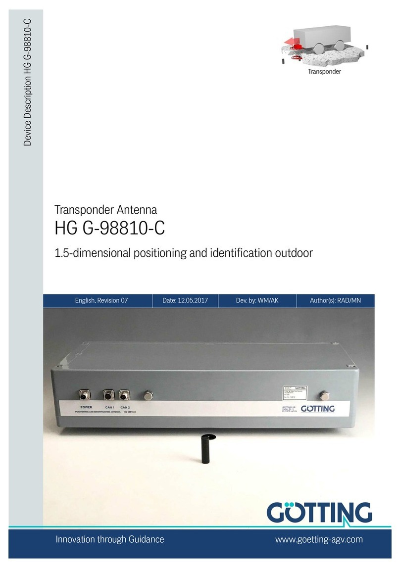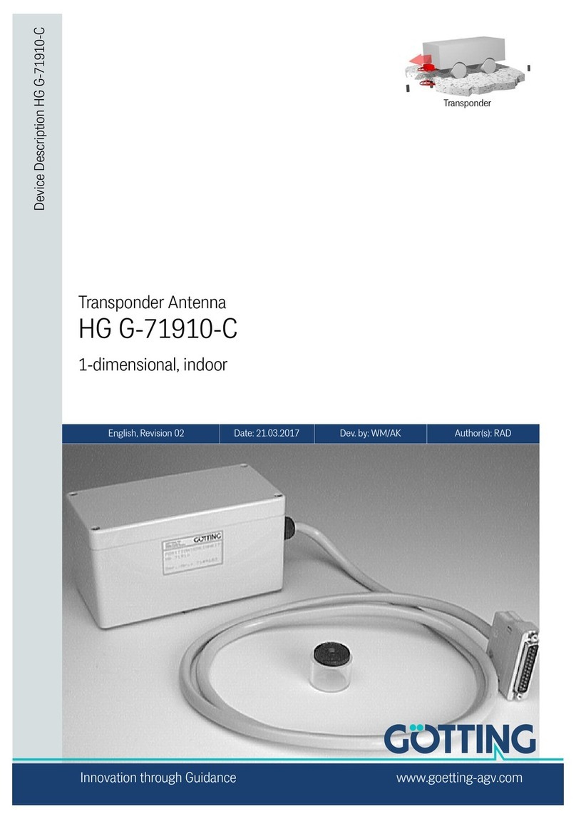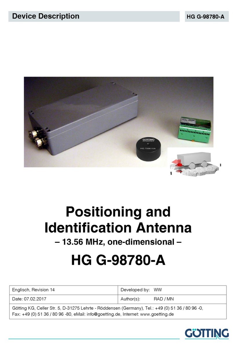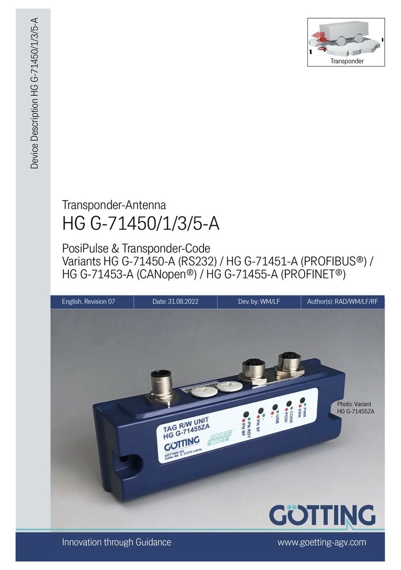
Device Description HG G-71910-C | English, Revision 03 | Date: 17.09.2019
3
Table of Contents
Contents
1 About this Document........................................................................ 5
1.1 Warning Notices.................................................................................................................... 5
1.2 Symbols ................................................................................................................................... 6
2 Introduction....................................................................................... 7
2.1 System Components............................................................................................................ 7
2.2 Function ................................................................................................................................... 8
3 Mounting ........................................................................................... 9
3.1 Metal-free Areas Around Transponder and Antenna ................................................. 9
3.1.1 Smaller Metallic Structures That do Not Form a Loop ......................................... 9
3.1.2 Closed Metallic Structures or Smaller Metallic Structures That
Form Loops ......................................................................................................................10
3.2 Transponder .........................................................................................................................10
3.3 Antenna HG 71910-C ........................................................................................................11
4 Installation / Commissioning ......................................................... 12
5 Components and Operation ........................................................... 16
5.1 Components in the Ground: Transponders ................................................................. 16
5.2 Transponder Antenna (Versions)....................................................................................16
5.2.1 Plug / Pin assignment ...................................................................................................17
5.2.1.1 Connection plan of the 7-pin-socket (HG 71910ZC) .......................................17
5.2.1.2 Connection plan of the alternative 26-pin flat band round ca-
ble / of the SUB-D connector (HG G-71910YC/XC/VC) ..................................18
5.2.1.3 Connection Plan of the 6 Pin Hirschmann Connector (HG G-
71910UC)......................................................................................................................18
5.2.2 Interfaces ..........................................................................................................................18
5.2.2.1 RS 232 (all Variants)..................................................................................................18
5.2.2.1.1 List of System Data that may be Output ........................................................ 19
5.2.2.1.2 List of System Commands ..................................................................................20
5.2.2.1.3 Programming of Transponders (serial) ...........................................................21
5.2.2.1.4 System Monitor ......................................................................................................21
5.2.2.2 Positioning Pulse (all Variants) .............................................................................. 21
5.2.2.3 CAN (Version HG G-71910ZC)................................................................................21
5.2.2.3.1 Description...............................................................................................................21
5.2.2.3.2 CAN Message Object 1 (Send-Object) ............................................................ 22
5.2.2.3.3 CAN Message Object 2 (Send-Object) ............................................................ 22
5.2.2.3.4 CAN Message Object 3 (Send-Object) ............................................................ 22
5.2.2.3.5 CAN Message Object 4 (Reception-Object, Transponder Pro-
gramming)................................................................................................................22
5.2.2.4 CANopen®....................................................................................................................23
5.2.2.4.1 Defaults.....................................................................................................................23
5.2.2.4.2 Description of the Process Data Objects (PDO) ........................................... 23
5.2.2.4.3 PDO_1 .......................................................................................................................23
5.2.2.4.4 PDO_2 .......................................................................................................................24
5.2.2.4.5 Heartbeat..................................................................................................................24
5.2.2.4.6 Node-Guarding .......................................................................................................24
5.2.2.4.7 Description Of The Service Data Objects (SDOs) ........................................ 24
5.2.2.4.8 Object Directory .....................................................................................................25
5.2.2.4.9 Explanation of the Entries CANopen® Directory ......................................... 27
5.2.2.5 Parallel Port (Versions HG 71910YC/XC/VC) .....................................................32
6 Software .......................................................................................... 33
