Spectravideo SVI-605 User manual

1
SUPER
EXPANDER
USER'S
MANUAL

USER’S
MAN
UAL
STATE
iWl
ENT
This
equipment
generates
and
uses
radio
frequency
energy
and
if
not
installed
and
used
properly,
that
is,
in
Strict
accordance
with
the
manufacturer’s
instructions,
may
cause
interference
to
radio
and
television
reception.
It
has
been
type
tested
and
found
to
comply
with
the
limits
for
a
Class
B
computing
device
in
accordance
with
the
specifications
in
Subpart
J
of
Part
15
of
FCC
Rules,
which
are
designed
to
provide
reasonable
protection
against
such
interference
in
a
residential
installation.
However,
there
is
no
guarantee
that
interference
will
not
occur
in
a
particular
i
installation.
If
this
equipment
does
cause
interference
to
radio
or
television
reception,
which
can
be
determined
by
turning
equipment
off
and
on,
the
user
is
encouraged
to
try
to
correct
the
interference
by
one
or
more
of
the
following
measures:
—
Reorient
the
receiving
antenna
—
Relocate
the
computer
with
respect
to
the
receiver
—
Move
the
computer
away
from
the
receiver
—
Plug
the
computer
into
a
different
outlet
so
that
computer
and
receiver
are
on
different
branch
circuits
I
f
necessary,
the
user
should
consult
the
dealer
or
an
experienced
radio/television
technician
for
additional
suggestions.
The
user
may
find
the
following
booklet
prepared
by
the
Federal
Communications
Commission
helpful:
“How
to
Identify
and
Resolve
Radio-TV
Interference
Problems”
This
booklet
is
available
from
the
U.S.
Government
Printing
Office,,
VVashington,
DC20402.
Stock
No.
004-000-00345-4.
WARNING:
This
equipment
has
been
certified
to
comply
with
the
limits
for
a
class
B
computing
device,
pursuant
of
Subpart
J
of
Part
15
of
FCC
Rules.
Only
peripherals
(computer
input/output
devices,
terminals,
printers,
etc.)
certified
to
comply
with
the
Class
B
limits
may
be
attached
to
this
computer.
Operation
with
non-certified
peripherals
is
likely
to
result
in
interference
to
radio
and
TV
reception.

INTRODUCTION
Spectravideo’s
Expander
Unit
SVI-605
is
specially
designed
to
offer
convenient
and
flexible
expansion
of
the
SVI-318/SVI-328MKII
computer
unit.
The
Expander
unit
connects
directly
to
the
system
bus
of
the
SVI-31
8/SVI-328
via
a
50-pins
connector.
With
the
addition
of
the
SVI-605,
the
SVI-318/SVI-328
can
interface
with
a
maximum
of
4
different
peripheral
devices
and
two
floppy
disk
drives
at
one
time.
The
metal
casing
of
the
SVI-605
which
is
helpful
to
eliminate
EMI
(electromagnetic
interference)
provides
rigid
and
durable
casing.
Moreover,
the
most
remarkable
feature
is
the
built-in
floppy
disk
drive,
disk
drive
controller
and
centronics
interface
in
the
Expander
Unit.
It
is
ready
to
utilize
disk
basic,
the
most
current
CP/M
programme
(with
sufficient
RAM
installed)
and
hard
copy
printout
with
the
addition
of
Centronics
printer.
Before
using
the
Expander
Unit,
please
read
this
manual
carefully.

SPECTRAVIDEO
SUPER
EXPANDER
SVI-605/SVI-605A
INSTRUCTION
MANUAL
CONTENTS
1
.
1
2
.
2
3
.
3
4
.
4
5
.15
6
.18
7
.19
8
.20
9.
1
O
Installation
of
the
Optional
Second
Disk
Drive.
.24
.26
11
.28
12.
Servicing
&
Trouble
shooting.
.29

1.
Packing
List
The
SVI-605
package
should
contain
the
following
items;
(A)
Expander
Unit
(B)
SVI-605
User’s
Manual
(C)
CP/M
Operating
System
Manual
(D)
CP/M
Command
Summary
(E)
CP/M
User’s
Guide
(F)
CP/M
2.20
Diskette
(G)
Disk
Basic
User’s
Guide
(H)
SV
Extended
Basic
Diskette
(I)
Six
Peripheral
indication
Inlays
(J)
Labels
sticker
with
words
(K)
Warranty
registration
card
1
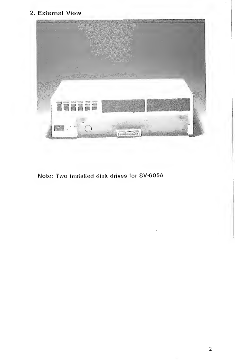
2.
External
View
Note:
i
wo
installed
disk
drives
for
SV-605A
2
3.
Main
Features
(A)
4
slots
to
accommodate
optional
interface
modules
supplied
in
cartridge
form.
(B)
Convenient
front
panel
read-out
for
selected
add-on
optional
expansion
and
interface
cartridges.
(C)
Expansion
cartridge
power-on
LED
indication.
(D)
Built-in
half
height
S’A”
Disk
Drive
provides
secondary
memory
capacity
and
high
access
speed.
(E)
Provide
power
supply
and
protection
circuitry
to
the
built-in
Floppy
Disk
Drive
and
the
various
optional
expansion
cartridges
connected.
(F)
Space
available
for
installation
of
second
optional
Floppy
Disk
Drive
for
SVI-605
and
two
drives
are
installed
in
SVI-605A.
(G)
Floppy
Disk
Controller
Cartridge
and
Centronics
Interface
Cartridge
are
built
in
the
circuit
board.
(H)
S
p
ecial
head
surface
for
maximum
signal
transfer
to
and
from
diskette
with
minimum
head/diskette
wear.
(I)
Stepping
motor
ensures
precision
positioning
of
the
read/write
head.
(J)
Use
industrial
standard
5.25”
flexible
single
sided,
double
density
diskette.
(K)
Fast
access
time:
approximate
88
msec.
(L)
Metal
and
sturdy
housing
capable
of
seating
a
14”
TV
monitor
(44
lbs/20
kg)
provides
good
shielding
to
EMI.
(M)
The
front
side
of
the
SVI-605
Expander
Unit
is
specially
engineered
tofitthe
rearside
of
the
SVI-318
or
SVI-328
computer
unit.
3
4.
Installation
4.1
Connections
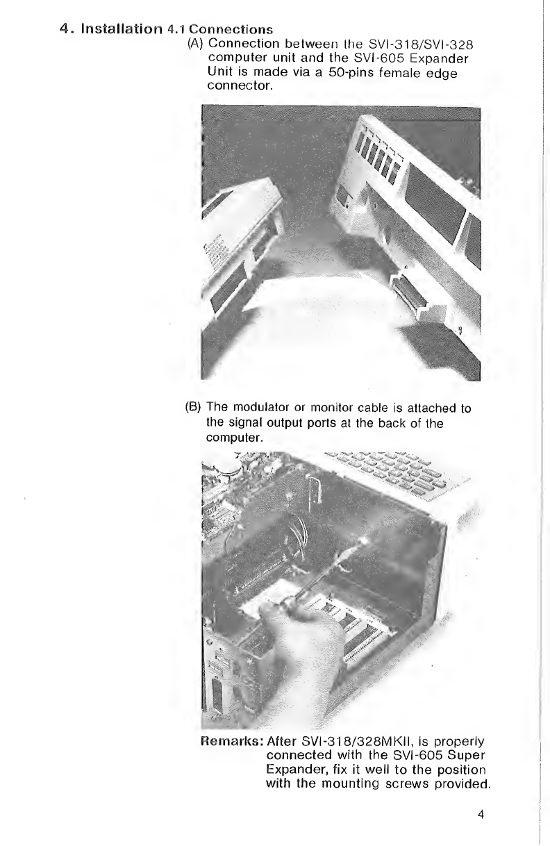
(A)
Connection
between
the
SVI-318/SVI-328
computer
unit
and
the
SVI-605
Expander
Unit
is
made
via
a
50-pins
female
edge
connector.
Remarks:
After
SVI-318/328MKII,
is
properly
connected
with
the
SVI-605
Super
Expander,
fix
it
well
to
the
position
with
the
mounting
screws
provided
4

(C)
Optional
interface
and
expansion
cartridges
can
be
inserted
in
any
of
the
4
slots,
from
SKO
to
SK3
(50-pins
socket).
(£)Cqpyflflht
:
(D)You
may
install
the
transformer
outside
the
Expander,cut
the
nylon
band
to
remove
it.

(E)
Dress
the
cable
of
the
transformer
through
the
hole
at
the
rear
panel
of
the
Expander.
Connect
it
to
the
socket
on
the
power
regulator
circuit
board
which
is
located
at
the
back
panel
of
the
Expander.
(F)
Connect
the
transformer
to
the
AC
power
supply.

4.2
Installation
of
the
optional
peripheral
interface
(A)
Description
of
the
rear
panel
of
the
Expander
1.
T
here
are
2
slots,
3
keyholes
and
1
rectangular
hole
at
the
rear
panel
of
the
Expander.
2.
The
two
slots
are
designed
to
mount
all
flat
interface
cables
while
the
rectangular
hole
is
specially
designed
to
mount
the
25
pins
D
type
socket
for
RS232.
The
three
keyholes
are
designed
for
the
monitor
cable,
RF
cable
as
well
as
the
80
column
cable.
3.
Both
two
slots
and
the
rectangular
hole
are
shielded
by
the
two
metallic
plates
provided.

4.
W
ith
one
shielding
plate
turns
up
side
down,
the
rectangular
hole
is
not
shielded.
This
allows
you
to
install
the
connector
of
the
RS232
cable
to
that
position.
5.
The
shielding
covers
are
designed
to
serve
the
following
purposes:
a)
good
metallic
contact
to
the
shielding
layer
of
flat
cable
to
eliminate
unwanted
EMI.
b)
acting
as
strain
relief
for
the
flat
cable.
c)
shielding
of
the
RS232
port
opening
if
it
is
not
occupied.
6.
Installation
Recommendations
In
general,
RAM
cards
are
recommended
to
be
located
at
slots
SK2,
3.
Other
peripherals
may
be
located
at
slots
SKO,
1
so
that
they
are
nearer
to
the
panel
opening.
8
(B)
Monitor
or
Modulator
Cable
Use
a
screwdriverto
remove
the
window
plate
which
covers
the
front
hole
of
the
Expander
Monitor
cable
for
SVI-318/328
1.
Attach
the
end
of
the
cable
connector
to
signal
output
ports
at
the
back
of
the
computer.
2.
Dress
the
video
and
audio
cables
through
the
front
hole
of
the
Expander
to
the
keyhole
at
the
rear
panel.
3.
Connect
the
cables
to
the
video
and
audio
inputs
of
the
monitor.
TV
cable
for
SVI-318/328
Mark
II
1.
Plug
the
end
of
the
cable
connector
to
signal
output
port
at
the
back
of
the
computer.
2.
Dress
the
cable
through
the
front
hole
of
the
Expander
to
the
keyhole
at
the
rear
panel.
3.
Connect
the
cables
to
the
input
of
the
TV.
Modulator
cable
for
SVI-318/328
1.
Fix
the
modulator
with
double
side
tape
at
the
location
beside
the
slots.
2.
Dress
the
modulator
cable
through
the
front
hole
of
the
Expander
and
attach
the
DIN
plug
to
the
RF
port
at
the
rear
of
thfe
computer.
3.
Connect
one
end
of
the
TV
cable
to
the
RCA
socket
on
the
modulatorand
the
other
end
to
the
TV
through
the
rear
panel
of
the
Expander.

(C)
Centronics
Interface
Cable
oArL'XSr
1
*
3
pla,e
at
back
2
'
Centronics
Sb^ihe
CeJ
^
05
wmtm
i
i
4.
Connect
the
other
end
of
the
cable
to
Ma?rix*Printer
nt6r
"
'
he
SVI
'
901
D
°'
to
the
AC
power
s
of
the
printer
10
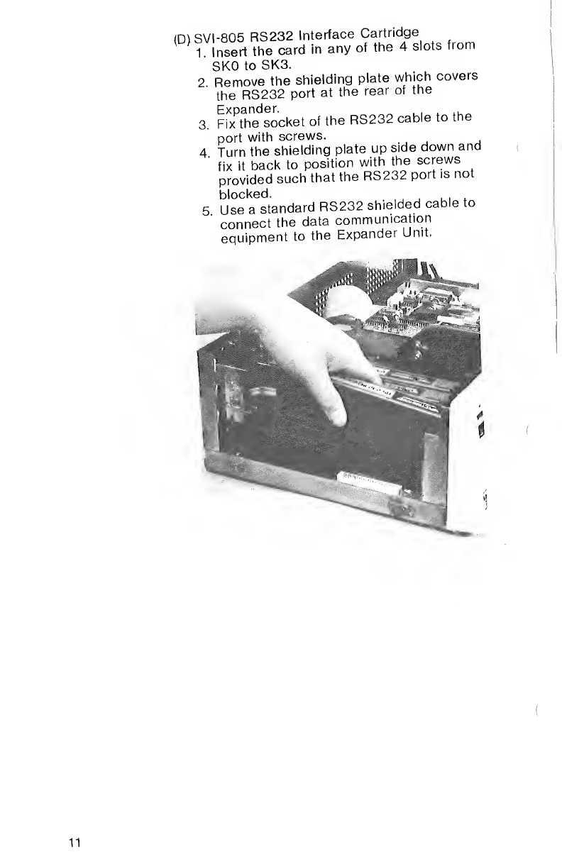
<mSVI-805
RS232
Interface
Cartridge
1.
Insert
the
card
in
any
of
the
4
slots
from
SKO
to
SK3.
2
Remove
the
shielding
plate
which
covers
the
RS232
port
at
the
rear
of
the
Expander.
„
.
.
,
.,_
3
Fix
the
socket
of
the
RS232
cable
to
th
port
with
screws.
4.
Turn
the
shielding
plate
up
side
down
and
fix
it
back
to
position
with
the
screws
provided
such
that
the
RS232
port
is
not
blocked.
5
Use
a
standard
RS232
shielded
cable
to
connect
the
data
communication
pnuinment
to
the
Expander
Unit.
11

(E)
SVI-806
80
Column
Video
Board
Cartridge
1.
Insert
the
card
into
any
of
the
4
slots
gently.
2.
Dress
the
cable
through
the
keyhole
on
the
rear
panel
of
the
Expander.
3.
Press
the
RCA
phono
connector
down
and
fix
it
to
the
position.
Fasten
the
mounting
ring.
4.
Attach
one
end
of
the
phono
cable
to
the
connector
and
the
other
end
to
the
monitor.

(F)
SVI-803/SVI-807
16K/64K
RAM
Cartridge
1.
Insert
the
card
into
any
of
the
4
slots
gently.
2.
The
SVI
-803
fills
the
first
half
of
Bank
0
Page
2
in
the
SVI-318
computer
unit.
3.
The
SVI-807
is
designed
to
fill
in
the
memory
banks
of
the
SVI-318/SVI-328
computer
units
with
the
use
of
DIP
switches.
Switch
Bank/Page
SI
21
S2
22
S3
31
S4
32
S5
02
S6
48K/32K
Bank
Memory
for
SVI-318
32K
page
bankO
bankl
bank2
bank3
*
RAM:
the
user
expandable
RAM
area
—>
RAM:
the
built-in
RAM
area
Total
:
there
are
144K
user
expandable
RAM
area.
Bank
Memory
for
SVI-328
—
S3
k
—
S2
■
k
S4
k
bankO
bankl
bank2
bank3
*
RAM:
the
user
expandable
RAM
area
RAM:
the
built-in
RAM
area
Total
:
there
are
96K
user
expandable
and
64K
built-in
RAM
Remark:
Prefer
to
put
SVI-803/807
RAM
cartridge
into
slots
SK2,
3.
For
details,
please
refer
to
the
corresponding
User
Manual.
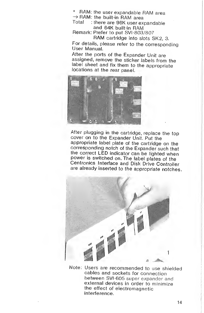
After
the
ports
of
the
Expander
Unit
are
assigned,
remove
the
sticker
labels
from
the
label
sheet
and
fix
them
to
the
appropriate
locations
at
the
rear
panel.
After
plugging
in
the
cartridge,
replace
the
top
cover
on
to
the
Expander
Unit.
Put
the
appropriate
label
plate
of
the
cartridge
on
the
corresponding
notch
of
the
Expander
such
that
the
correct
LED
indicator
can
be
lighted
when
power
is
switched
on.
The
label
plates
of
the
Centronics
Interface
and
Disk
Drive
Controller
are
already
inserted
to
the
appropriate
notches
Note:
Users
are
recommended
to
use
shielded
cables
and
sockets
for
connection
between
SVI-605
super
expander
and
external
devices
in
order
to
minimize
the
effect
of
electromagnetic
interference.
14

5.
Operations
(A)
Operations
of
the
Cartridges
1.
Connect
the
SVI-605
to
the
SVI-318
or
SVI-328
before
turning
on
power.
2.
Never
switch
on
the
power
until
all
connections
are
properly
made.
3.
Switch
on
the
power.
The
power-on
LED
indicator
will
illuminate.
4.
All
operations
of
interface
cartridges
and
associated
peripherals
are
controlled
by
the
host
computer
SVI-318
or
SVI-328
MKII.
For
details
to
the
individual
interface
cartridges
manuals.
(B)
Operation
of
the
Centronics
Printer
with
SVI-605
Super
Expander
1.
Under
Disk
Basic
To
print
a
file,
load
the
programme
and
then
“LUST”
it
on
the
paper.
The
following
commands
are
used.
LOAD
“<disk
drive#>
:
<filename>”
lENTERl
,_,
e.g.
LOAD
“1
:
TEST”
lENTERl
OK
r
_,
LLIST
lENTERl
The
programme
will
be
listed
on
the
paper.
2.
Under
CP/M
If
you
want
to
print
a
file,
just
enter
the
following
statement,
the
computer
will
do
it
for
you.
<disk
drive
#>
>
PIP
PRN:
=
<filename>
lENTERl
--.
e.g.
B
>
PIP
PRN;
=
DUMPASM
lENTERl
(C)
O
p
eration
of
the
diskette
1.
Before
inserting
a
diskette,
make
sure
that
the
connections
on
all
the
appliances
involved
are
correctly
made
and
power
is
switched
on.
15

2.
M
o
ve
the
disk
lock
to
the
horizontal
position.
Remove
the
card
which
protects
the
read/write
head
during
transportation
in
the
disk
drive.
3.
W
ith
the
diskette
label
facing
up
and
the
head
window
towards
the
slot,
insert
the
diskette
into
the
slot.
'A
4.
P
ush
the
diskette
lightly
until
it
stops
and
move
the
lock
to
the
vertical
position
as
shown.
If
the
diskette
is
not
inserted
all
the
way,
the
lock
cannot
be
moved
down.
When
this
happens,
do
not
force
the
lock
but
re-insert
the
diskette
correctly.
16
This manual suits for next models
1
Table of contents


