Spectrex Incite Fire SharpEye FS-1200 User manual


Legal Notice
The SPECTREX SharpEye Flame Simulator described in this document is the property of Rosemount.
No part of the hardware, software or documentation may be reproduced, transmitted, transcribed, stored in a
retrieval system or translated into any language or computer language, in any form or by any means, without prior
written permission of Rosemount.
While great efforts have been made to assure the accuracy and clarity of this document, Rosemount assSimulator
Statusumes no liability resulting from any omissions in this document, or from misuse of the information obtained
herein. The information in this document has been carefully checked and is believed to be entirely reliable with all
of the necessary information included. Rosemount reserves the right to make changes to any products described
herein to improve reliability, function, or design, and reserves the right to revise this document and make changes
from time to time in content hereof with no obligation to notify any persons of revisions or changes. Rosemount
does not assume any liability arising out of the application or any use of any product or circuit described herein;
neither does it convey license under its patent rights or the rights of others.
Warranty
SPECTREX agrees to extend to Purchaser/Distributor a warranty on the SPECTREX supplied components of the
SharpEye products. SPECTREX warrants to Purchaser/Distributor that the products are free from defects in
materials and workmanship for a base period of two (2) years for the Flame Simulator, twelve (12) months for the
battery and six (6) months for the charger, commencing with the date of delivery to Purchaser/Distributor.
SPECTREX expressly excludes damage incurred in transit from the factory or other damage due to abuse, misuse,
improper installation, or lack of maintenance or “Act of God” which are above and beyond its control. SPECTREX
will, upon receipt of any defective product, transportation prepaid, repair or replace it at its sole discretion if found
to have been defective when shipped. Said repair or replacement is SPECTREX’S sole liability under this warranty
and SPECTREX’S liability shall be limited to repair or replacement of the component found defective and shall not
include any liability for consequential or other damages. The customer is responsible for all freight charges and
taxes due on shipments both ways. This warranty is exclusive of all other warranties express or implied.
TM380102 Rev. (Ad), September 2020

TM380102 Rev. (Ad), September 2020 v
Table of Contents
Table of Contents ............................................................................................ v
List of Figures ............................................................................................... vii
List of Tables................................................................................................. vii
1About this Guide ........................................................................................ 9
1.1 Release History...................................................................................... 9
1.2 Glossary and Abbreviations ....................................................................10
2Product Overview .................................................................................... 13
2.1 Flame Simulator Compatibility with Flame Detector Models ........................13
2.2 Features and Benefits ............................................................................14
2.3 Principles of Operation ...........................................................................14
2.4 Product Certification ..............................................................................14
2.4.1 ATEX, IECEx...................................................................................14
2.4.2 cCSAus..........................................................................................14
2.4.3 TR CU/EAC.....................................................................................14
2.5 Simulator Structure...............................................................................16
2.6 Certification Instructions ........................................................................18
2.6.1 General Instructions........................................................................18
2.6.2 Specific Conditions of Use ................................................................19
3Operation Instructions ............................................................................ 21
3.1 Ordering Information.............................................................................21
3.2 Unpacking............................................................................................21
3.3 Operating Instructions ...........................................................................22
3.4 Simulator Status ...................................................................................22
3.4.1 Normal Status ................................................................................22
3.4.2 Fault Status ...................................................................................22
3.5 Detection Ranges ..................................................................................23
3.6 Charging the Battery .............................................................................23
3.7 Maintenance.........................................................................................25
3.8 Troubleshooting ....................................................................................26
3.9 Technical Specifications .........................................................................26
3.9.1 General Specifications .....................................................................26
3.9.2 Electrical Specifications....................................................................26
3.9.3 Physical Specifications .....................................................................26


TM380102 Rev. (Ad), September 2020 vii
List of Figures
Figure 1: Flame Simulator Side View ...................................................................16
Figure 2: Flame Simulator Rear View ...................................................................17
Figure 3: Flame Simulator Front View ..................................................................17
Figure 4: Flame Simulator Battery Replacement....................................................25
List of Tables
Table 1: Detection Ranges per Detector/Flame Simulator .......................................23

About this Guide
TM380102 Rev. (Ad), September 2020 9
1About this Guide
This guide describes the SharpEye Flame Simulator and its features, and provides
instructions on how to operate and maintain the simulator.
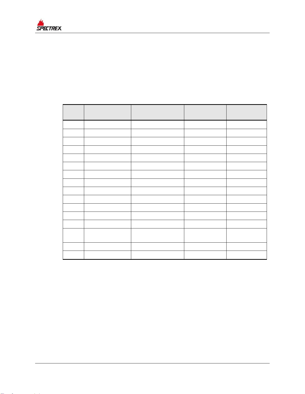
1.1 Release History
Rev
Date
Revision History
Prepared by
Approved
by
0
December 2015
First Release
Ian Buchanan
Eric Zinn
1
December 2015
Second Release
Ian Buchanan
Eric Zinn
2
January 2016
Third Release
Ian Buchanan
Eric Zinn
3
March 2016
Fourth Release
Ian Buchanan
Eric Zinn
4
April 2016
Fifth Release
Ian Buchanan
Eric Zinn
5
May 2016
Sixth Release
Ian Buchanan
Eric Zinn
6
May 2016
Seventh Release
Ian Buchanan
Eric Zinn
7
July 2016
Eighth Release
Ian Buchanan
Eric Zinn
8
January 2017
Ninth Release
Jay Cooley
Ian Buchanan
9
February 2017
Tenth Release
Jay Cooley
Ian Buchanan
10
February 2017
Eleventh Release
Jay Cooley
Ian Buchanan
11
April 2017
Twelfth Release
Jay Cooley
Shaul Serero
Aa
August 2017
Thirteenth Release
Jay Cooley
Shaul Serero
Ab
March 2018
Fourteenth
Release
Michal Heller
Udi Tzuri
Ac
December 2019
Fifteenth Release
Michal Heller
Udi Tzuri
Ad
September 2020
Sixteenth Release
Michal Heller
Udi Tzuri

About this Guide
10 SharpEye™ UV/IR Flame Simulator User Guide
1.2 Glossary and Abbreviations
Abbreviation/Term
Meaning
Analog Video
Video values are represented by a scaled signal
ATEX
Atmosphere Explosives
AWG
American Wire Gauge
BIT
Built-In-Test
CMOS
Complementary Metal-Oxide Semiconductor image
sensor
Digital Video
Each component is represented by a number
representing a discrete quantization
DSP
Digital Signal Processing
EMC
Electromagnetic Compatibility
EMI
Electromagnetic Interference
EOL
End of Line
FOV
Field of View
HART
Highway Addressable Remote Transducer –
communications protocol
IAD
Immune at Any Distance
IECEx
International Electro-Technical Commission
Explosion
IP
Internet Protocol
IPA
Isopropyl Alcohol
IR
Infrared
IR3
Refers to the 3 IR sensors
JP5
Jet Fuel
LED
Light Emitting Diode
MODBUS
Serial communications protocol using Master-Slave
messaging
N/A
Not Applicable
N.C.
Normally Closed
NFPA
National Fire Protection Association
N.O.
Normally Open
NPT
National Pipe Thread
P/N
Part Number
RFI
Radio Frequency Interference
RTSP
Real Time Streaming Protocol
SIL
Safety Integrity Level

About this Guide
TM380102 Rev. (Ad), September 2020 11
Abbreviation/Term
Meaning
UNC
Unified Coarse Thread
VAC
Volts Alternating Current

Product Overview
TM380102 Rev. (Ad), September 2020 13
2Product Overview
To comply with local standards and jurisdictional authorities, "end-to-end" loop
testing of fire protection alarm systems, including detectors, should be performed
periodically. Many safety authorities and plant managers of high-value/high-risk
assets and facilities insist on quarterly "end-to-end" testing of their entire fire
protection systems using an external flame simulator.
SPECTREX flame simulators emit electromagnetic radiation in a unique sequential
pattern corresponding to and recognizable as fire by specific SharpEye Flame
Detector models. This allows for testing under real fire conditions without the
associated risks of an open flame. SPECTREX flame simulators are ATEX certified
EExd for use in hazardous zones 1 and 2, and are powered by rechargeable
lithium-ion batteries. When fully charged, the flame simulator operates for at
least 100 tests without recharging.
The SPECTREX flame simulator is the only non-hazardous and safe method to
test the flame detector’s sensors, internal electronics, alarm activation software,
cleanliness of the viewing window/lens, wiring integrity, actual relay activation,
and proper functionality of any other outputs used (mA, RS-485, HART).
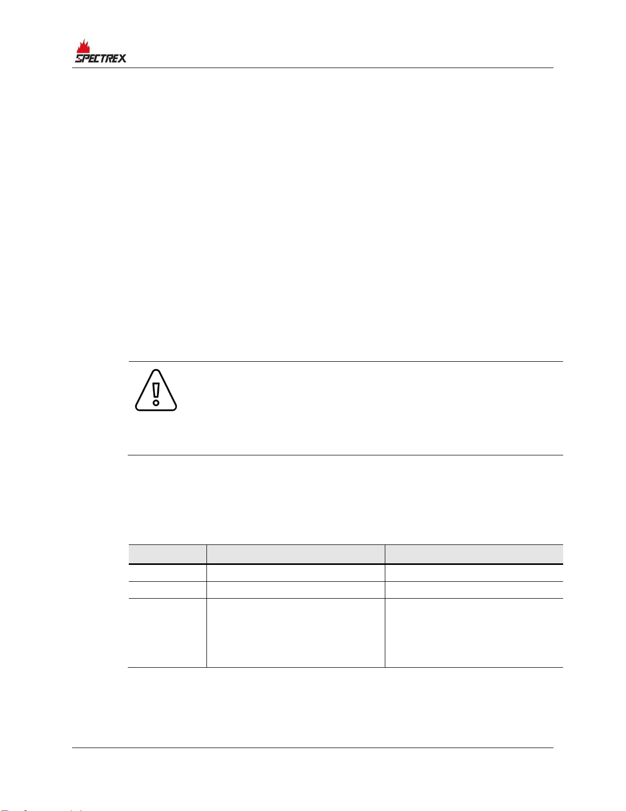
Warning:
The Simulator is not field-repairable due to the meticulous alignment
and calibration of the sensors and the respective circuits. Do not
attempt to modify or repair the internal circuits or change their
settings, as this will impair the system's performance and void the
SPECTREX product warranty.
2.1 Flame Simulator Compatibility with Flame Detector
Models
The FS-1200 Flame Simulator is compatible with several detector types:
Simulator
P/N
Compatible with:
UV/IR Flame
Simulator
FS-1200
40/40L-LB, 40/40L4-L4B,
40/40C-LB, 40/40C-L4B,
40/40D-LB, 40/40D-L4B,
40/40U-UB, 40/40UFL
20/20ML

Product Overview
14 SharpEye™ UV/IR Flame Simulator User Guide
2.2 Features and Benefits
•Used for maintenance and testing of flame detectors
•Ability to activate the flame detector from a distance of up to 10m
•Rechargeable battery included
•Operates at least 100 tests before battery recharge is necessary
2.3 Principles of Operation
The FS-1200 includes a halogen lamp that emits UV and IR energy. This energy
is accumulated by a reflector and directed towards the detector.
The FS-1200 does not include a laser diode. It includes only a mechanical sight,
as the user can see the spot from the simulator and should aim the spot toward
the center of the detector.
2.4 Product Certification
The Flame Simulator has the following certifications:
•ATEX, IECEx, page 14
•cCSAus, page 14
•TR CU/EAC, page 14
2.4.1 ATEX, IECEx
Ex II 2 G D
Ex db ib IIB + H2 T4 Gb
Ex ib tb IIIC T135°C Db
-4°F to +122°F / -20°C to +50°C
2.4.2 cCSAus
Class I, Zone 1, AEx db ib op is IIB+H2 T4 Gb
-20°C ≤ Ta ≤ +50°C
2.4.3 TR CU/EAC
1Ex db ib op is IIB+H2 T5 Gb X
-20°C ≤ Ta ≤ +50°C
This product is suitable for use in hazardous zones 1 and 2 with IIB + H2 gas
group vapor present.

Product Overview
TM380102 Rev. (Ad), September 2020 15
Product Overview
16 SharpEye™ UV/IR Flame Simulator User Guide
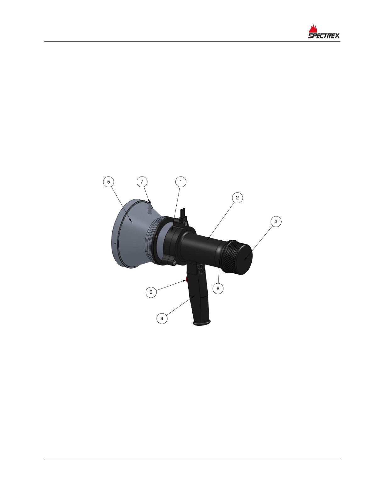
2.5 Simulator Structure
The flame simulator has a black-coated aluminum ex-proof enclosure. It includes
the following components:
•Reflector
•Electronic compartment
•Battery compartment
•Handgrip
The electronic compartment includes the internal optical and electronic parts of
the device.
The battery compartment includes a battery pack containing 4 lithium-ion
batteries, measuring a total of 14.8VDC and 2.6Ah.
To charge or replace the battery pack, follow the instructions in section 3.6 on page 23.
Figure 1: Flame Simulator Side View

Product Overview
TM380102 Rev. (Ad), September 2020 17
Figure 2: Flame Simulator Rear View
Figure 3: Flame Simulator Front View

Product Overview
18 SharpEye™ UV/IR Flame Simulator User Guide
1
Electronic Compartment
5
Reflector
2
Battery Compartment
6
Push Button
3
Battery Back Cover
7
Sight
4
Handgrip
8
Back Cover Locking Screw
2.6 Certification Instructions
2.6.1 General Instructions
The equipment marking is defined as follows:
Ex II 2 G D
Ex db ib IIB + H2 T4 Gb
Ex ib tb IIIC T135°C Db
-20°C to +50°C / -4°F to +122°F
•The equipment may be used with flammable gasses and vapors with
apparatus groups IIA and IIB+H2 T4 in the ambient temperature range of -
4°F to +122°F / -20°C to +50°C.
•Inspection and maintenance of this equipment should be performed by
suitable trained personnel, in accordance with the applicable code of practice,
e.g. EN 60079-17.
•Repair of this equipment should be performed by suitable trained personnel,
in accordance with the applicable code of practice e.g. EN 60079-19.
•Certification of this equipment relies upon use of the following materials in its
construction:
•Enclosure: Aluminum 6061T6
•Window: Sapphire glass
•Seals: EPDM
•If the equipment is likely to come into contact with aggressive substances
(described below), then it is the responsibility of the user to take suitable
precautions (described below) to prevent the equipment from being adversely
affected. This ensures that the type of protection provided by the equipment
is not compromised.
•Examples of aggressive substances: acidic liquids or gases that may
attack metals or solvents, or may affect polymeric materials.
•Examples of suitable precautions: routine inspections, establishing
resistance to specific chemicals from the material’s data sheets.

Product Overview
TM380102 Rev. (Ad), September 2020 19
2.6.2 Specific Conditions of Use
•The dimensions of the flameproof joints are other than the relevant minimum
or maximum values required by Table 3 of IEC/EN 60079-1:2014 for IIB +
H2, as detailed below:
Flamepath Description
Type of Joint
Minimum Width
“L” (mm)
Maximum Gap
“ic” (mm)
Joint formed by window
against the enclosure
Flanged
10.75
0.02
Enclosure end-cap spigot
Cylindrical
15
0.08
Gaps should not be machined to be any larger than the values of “ic,” and width
should not be modified to be any smaller than the values of “L,” as shown in the
table above.
•The equipment should only be charged in a safe area. Batteries must be
removed from the flameproof enclosure. The charge conditions are as follows:
•Maximum charge voltage: 16.8V
•Maximum charge current: 4A
The charge voltage and current should not exceed these values.


Operation Instructions
TM380102 Rev. (Ad), September 2020 21
3Operation Instructions
3.1 Ordering Information
The P/N of the Flame Simulator Kit is 380114-2.
The kit is supplied in a carry case that includes:
•Flame Simulator FS-1200
•Charger
•Tool Kit
•Technical Manual TM380102
3.2 Unpacking
Verify that you have received the following components:
•Delivery form
•Flame simulator with integral battery
•Battery charger
•Tool keys
•User manual
•FAT forms
•EC declaration
•Storage case
Note:
The FS shall be stored in a suitable suitcase to prevent possible
damage during handling
Warning:
Do not open when an explosive atmosphere is present. Use only
replaceable battery pack P.N. 380015

Operation Instructions
22 SharpEye™ UV/IR Flame Simulator User Guide
3.3 Operating Instructions
1Verify you are using the correct simulator that fits the tested detector, per
section 2.1 on page 13
2Verify you are at the correct distance from the detector according to the type
of detector and the detector sensitivity (See Simulator Status on page 22).
3Using the mechanical sight, aim the flame simulator toward the center of the
detector.
4Push the activate button; direct the halogen beam toward the center of the
detector.
5Once the trigger is pressed, with an initial 2 seconds delay, the equipment will
operate for a maximum period of 60 seconds, following which the equipment
cannot be operated for a minimum period of 30 seconds.
3.4 Simulator Status
During the first 5 seconds of operation, the simulator performs self-test for
operating status.
3.4.1 Normal Status
When switching to normal status, the equipment will operate for a maximum
period of 60 seconds, following which the equipment cannot be operated for a
minimum period of 30 seconds.
3.4.2 Fault Status
•Low Battery –When the battery is lower than 12.3 VDC, the lamp won’t be
activated.
This manual suits for next models
1
Table of contents
Popular Switch manuals by other brands


Vega
Vega VEGACAP 65 operating instructions

Windbit
Windbit ESW1L3 Series Hardware installation and reference guide

Dungs
Dungs AA-A1-0 Series installation instructions

Dell
Dell PowerConnect 6224 release note

Linkskey
Linkskey LKV-M02 Quick installation guide

TIL
TIL AMS-6000 Installation and operating instructions

Huawei
Huawei CR-SRUB Specifications

IFM Electronic
IFM Electronic efector 150 operating instructions

Intelix
Intelix VGA2-SW4 installation guide

Planet Networking & Communication
Planet Networking & Communication WGS-4215-8P2S user manual

SMC Networks
SMC Networks 8606SX - FICHE TECHNIQUE manual

AV Access
AV Access 4KMX42-H2A user manual