IFM Electronic efector 150 User manual

Bedienungsanleitung
Operating instructions
Notice utilisateurs
Kapazitiver
Näherungsschalter KW
Capacitive proximity
switch KW
Détecteur de proximité
capacitif KW
DEUTSCHENGLISHFRANÇAIS
Sachnr. 701641/00 02/2006

Inhalt Seite
1. Bestimmungsgemäße Verwendung ---------------------------------- 2
2. Montage ------------------------------------------------------------------ 3
3. Elektrischer Anschluß -------------------------------------------------- 3
4. Bedienung ---------------------------------------------------------------- 4
5. Programmieren -------------------------------------------------------------- 5
6. Inbetriebnahme / Betrieb ---------------------------------------------- 9
7. Anschlußschema ------------------------------------------------------ 27
1. Bestimmungsgemäße Verwendung
Der Näherungsschalter erfaßt berührungslos Metalle, nahezu alle
Kunststoffe, Glas, Keramik, Holz, Papier, Öle, Fette, Wasser und alle
wasserhaltigen Materialien und meldet sie durch ein Schaltsignal.
• Nennschaltabstand (Sn) 12mm b; (Messung auf geerdete Metall-
platte und Wasser; bei anderen Materialien kürzer).
• Automatischer Abgleich durch den Anwender auf das zu erfassen-
de Objekt.
2
4
5
5
1
2
3
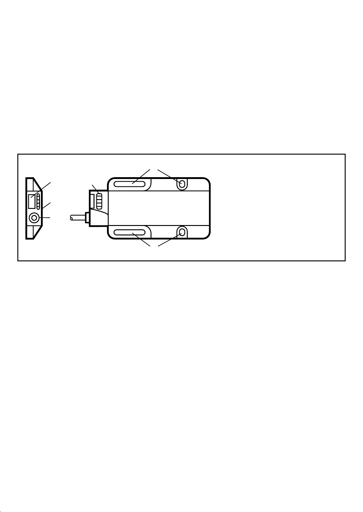
(1) Teach-In-Element
(2) Elektrischer Anschluß
(Steckverbindung oder
Anschlußleitung)
(3) Aktive Fläche
(4) LEDs rot, gelb, grün
(5) 4 Befestigungsbohrungen

DEUTSCH
2. Montage
Für die Montage können Sie die vorhandenen Befestigungsbohrungen
nutzen.
Beim bündigen Einbau nachfolgende Skizze beachten:
Mindestabstände bei Montage mehrerer Schalter gleichen Typs:
3. Elektrischer Anschluß
Schalten Sie die Anlage spannungsfrei. Schließen Sie das Gerät
an (Seite 27 oder Typenschild).
Adernfarben: BN = braun, BU = blau, BK = schwarz, WH = weiß
Funktionskontrollausgang / Programmierleitung Pin2/WH
Dies ist eine bidirektionale Leitung.
•Als Funktionskontrollausgang können Ausgangsignale vom Gerät
ausgewertet werden.
•Als Programmierleitung können Bedienvorgänge ausgelöst werden.
Signale am Funktionskontrollausgang
Zustand Signal
Funktionskontrolle Funktionskontrollausgang ist leitend
Abgleichfehler Ausgang wechselt mit 7 Hz zwischen
leitendem und gesperrtem Zustand
3
3 x SnBBB
4
Anschluss Programmierleitung
Gerätetyp Auslösung eines Bedienvorganges
p-schaltend zum Aktivieren der Funktion wird die Leitung elektrisch
mit Leitung "L+" verbunden.
n-schaltend zum Aktivieren der Funktion wird die Leitung elektrisch
mit Leitung "L-" verbunden.
4. Bedienung
Der Sensor wird entweder über das induktive Teach-In-Element oder
die Programmierleitung bedient.
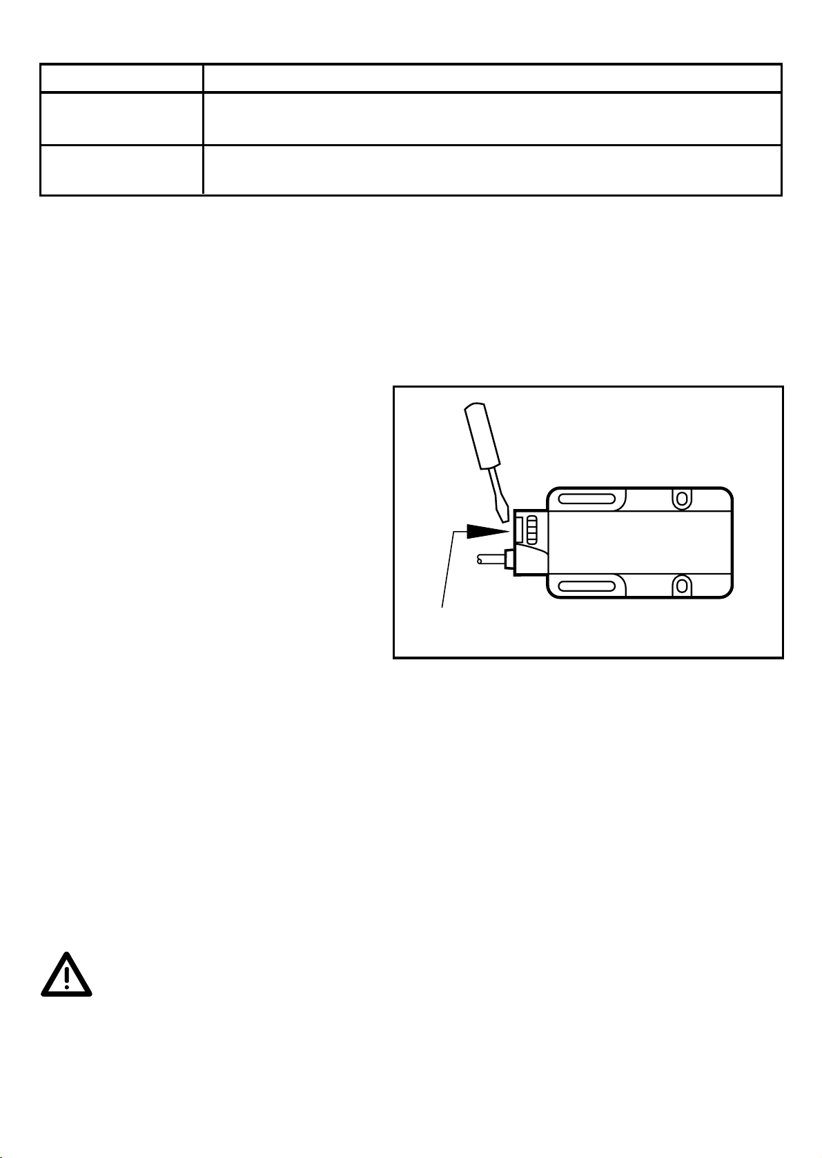
Teach-In-Element
Wenn Sie das entsprechend
markierte Feld mit einem metal-
lischen Gegenstand (z.B.
Schraubendreher) berühren,
dann wird das Teach-In-Element
aktiviert.
Wenn Sie den Gegenstand wie-
der von dem Feld entfernen,
wird das Teach-In-Element wie-
der deaktiviert.
Mit "Betätigung" ist im Folgenden ein einfacher Berührungsvorgang
aus aktivieren und wieder deaktivieren des Teach-In-Elementes ohne
besondere zeitliche Bedingungen gemeint.
Bedienung über Programmierleitung (Pin2/WH)
Sie können die nachfolgenden Bedienvorgänge auch über die Pro-
grammierleitung durchführen. Ein Signal auf diesem Eingang ent-
spricht dem Betätigen des Teach-In-Elements.
Die Programmierung über das Teach-In-Element hat Vorrang
gegenüber der Programmierleitung (Pin 2/WH). Eine beginnende
oder bereits laufende Programmierung über die Programmierlei-
tung wird durch die Betätigung des Teach-In-Elements blockiert.
Berührungsfläche des Teach-In-Elements
DEUTSCH
5. Programmieren
Einstellen der Schaltschwelle bei stillstehenden Objekten
Das Gerät erfaßt die Zustände "Objekt vorhanden" und "Objekt nicht
vorhanden" und gleicht die interne Schaltschwelle elektronisch ab.
5
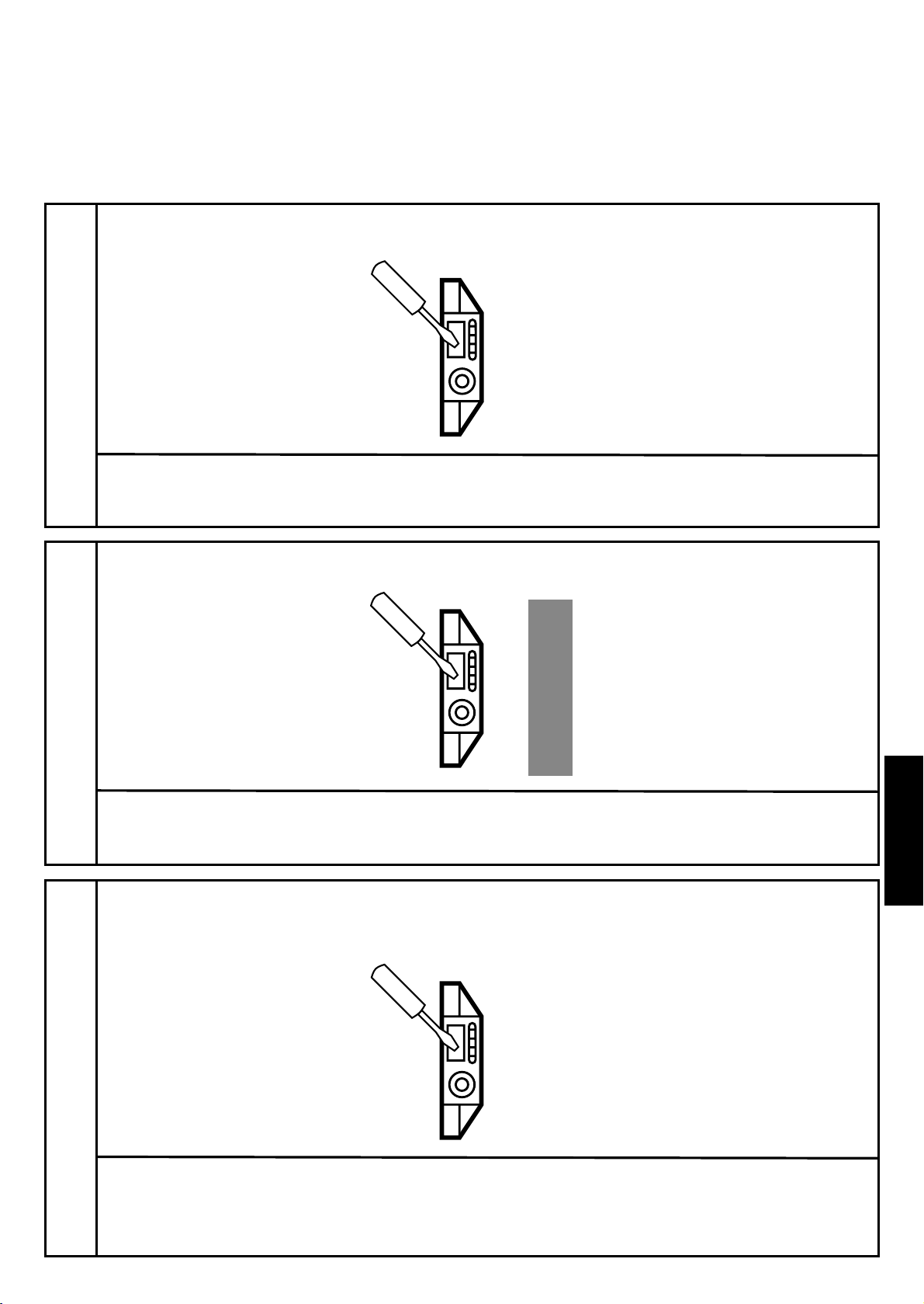
1
Gerät in den Abgleichmodus bringen.
Betätigen Sie das
Teach-In-Element für 2s.
LEDs gelb und grün blinken im Wechsel (1 Hz).
Das Gerät ist im Abgleichmodus.
2
Plazieren Sie das Objekt im Erfassungsbereich des Sensors.
Betätigen Sie kurz das
Teach-In-Element.
LEDs gelb und grün verlöschen kurz, blinken dann schnell im Wechsel
(2 HZ). LED rot leuchtet.
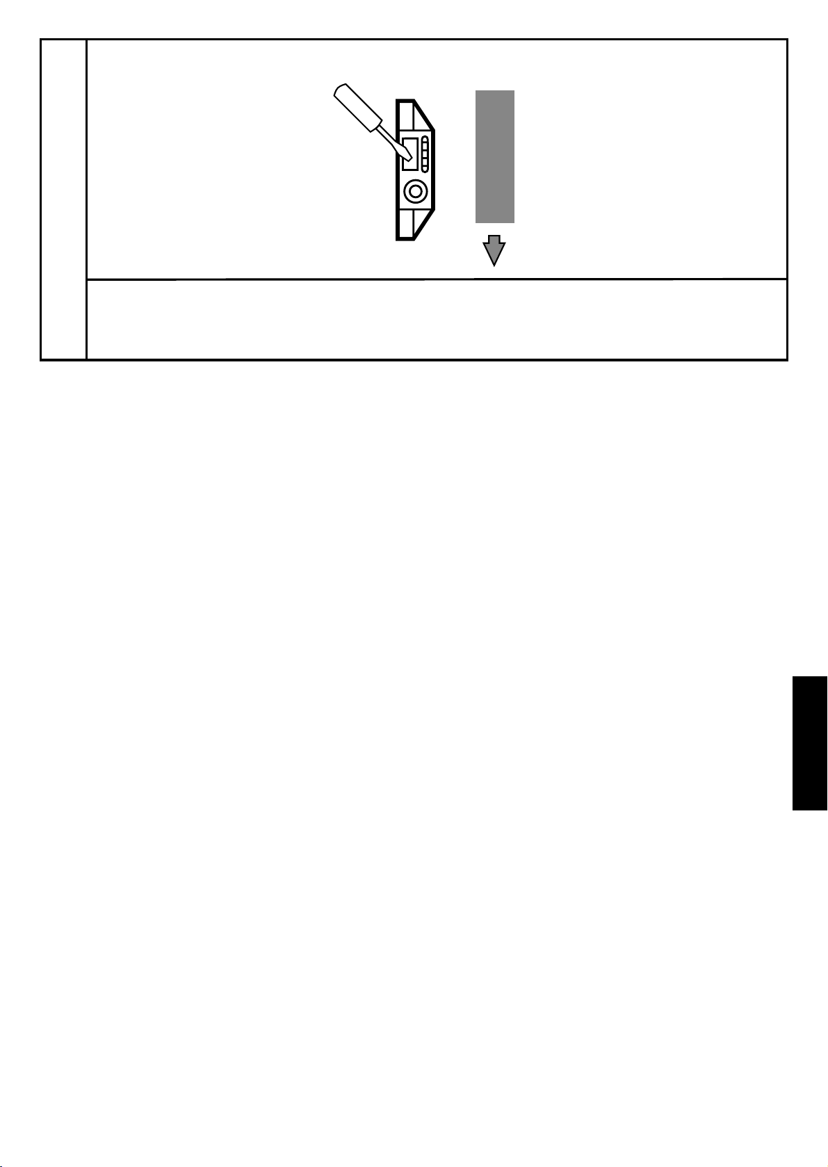
3Betätigen Sie kurz das
Teach-In-Element.
LEDs gelb und grün verlöschen kurz, danach leuchtet LED grün.
LED gelb zeigt den aktuellen Schaltzustand an.
Das Gerät ist im Betriebsmodus.
Entfernen Sie das Objekt oder vergrößern Sie den Abstand zwischen
Objekt und Gerätbis die rote LED verlischt.

Bei Schritt 2 und 3 können Sie auch in umgekehrter Reihenfolge vorgehen:
Zuerst ohne Objekt einstellen, dann das Objekt in den Erfassungsbereich brin-
gen, bis die rote LED verlischt.
Einstellen der Schaltschwelle bei bewegten Objekten
Wenn schnelle, sich regelmäßig wiederholende Vorgänge (z.B. Zähl-
vorgänge) erfasst werden sollen, die schneller als 2 Hz (bis max. 40 Hz)
sind, bietet das Gerät die Möglichkeit im laufenden Prozess durch eine
Maximum-Minimum-Erkennung die Schaltschwelle einzustellen.
6
1
Montieren Sie das Gerät so, dass sich das zu erfassende Objekt sich im
Erfassungsbereich der Aktiven Fläche befindet. Das Objekt befindet
sich im laufenden Prozess (schneller als 2 Hz).
Betätigen Sie das
Teach-In-Element für 2s.
LEDs gelb und grün blinken im Wechsel (1 Hz).
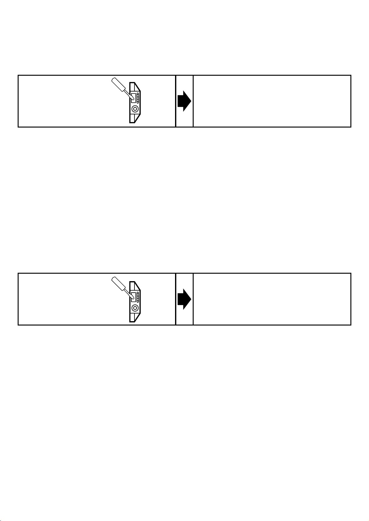
2Betätigen Sie kurz das
Teach-In-Element.
LEDs gelb und grün blinken im Wechsel (2 Hz),
zusätzlich leuchtet die rote LED dauerhaft.
Das Objekt befindet sich weiterhin im laufenden Prozess (schneller
als 2 Hz).
DEUTSCH
Fehlermeldung
Ist der Abgleich nicht möglich, blinkt die rote LED nach dem Abgleich-
versuch schnell ca. 7 Hz (Abgleichfehler). Zum Löschen dieser Fehler-
meldung betätigen Sie 1 mal das Teach-In-Element oder schalten Sie
die Betriebsspannung aus und wieder ein. Die bisher erfolgreich ein-
gelesenen Abgleichpositionen bleiben dabei unverändert erhalten.
Mögliche Ursachen eines Abgleichfehlers:
•Bei stillstehendem Objekt
Der Signalabstand zwischen dem Abgleich mit Objekt und demjeni-
gen ohne Objekt ist zu gering.
Abhilfe: Verkleinern Sie den Abstand zwischen Gerät und Objekt
und wiederholen Sie den Abgleich.
•Bei bewegtem Objekt
a) Die Frequenz ist zu niedrig und dadurch ist die Bewegungserken-
nung nicht aktiv.
Abhilfe: Erhöhen Sie die Frequenz oder gleichen Sie mit stillstehen-
dem Objekt ab.
b) Die Frequenz ist zu hoch und dadurch ist der Signalabstand zu
klein
Abhilfe: Verkleinern Sie den Abstand zwischen Gerät und Objekt
oder setzten Sie die Frequenz herab. Wiederholen Sie den Abgleich.
Weitere Fehlerarten (Diese Fehler sind keine Abgleichfehler)
•Elektronischer Fehler oder Beschädigung des Gerätes im Sensorbe-
reich
•Interner Fehler (kann nur durch aus- und wieder einschalten der
Betriebsspannung gelöscht werden, Hardware-Reset)
7
3Betätigen Sie kurz das
Teach-In-Element.
LEDs gelb, grün und rot verlöschen, danach leuchtet LED grün.
Die LED gelb und der Schaltausgang sollten jetzt der
Objektbewegung folgen.
Das Objekt befindet sich weiterhin im laufenden Prozess (schneller als
2 Hz).
Verriegeln
Die gespeicherten Abgleichwerte können gegen unberechtigtes Pro-
grammieren wie folgt gesichert werden (Ausgangszustand "nicht ver-
riegelt"):
Beim Deaktivieren des Teach-In-Elementes wird nun das Gerät verrie-
gelt und alle Programmierfunktionen sind gesperrt. Das Gerät springt
zurück in den Betriebsmodus (LED grün leuchtet).
Entriegeln
Wird dieser Vorgang aus dem verriegelten Zustand heraus gestartet, so
zeigt die grüne LED zunächst keine Reaktion, um jeden Hinweis auf
eine versteckte Funktion zu vermeiden.
Wenn Sie also die Verriegelung wieder freigeben wollen, gehen Sie wie
folgt vor:
Beim Deaktivieren des Teach-In-Elementes wird nun das Gerät entrie-
gelt und alle Programmierfunktionen sind wieder freigegeben. Das
Gerät springt zurück in den Betriebsmodus.
8
Nach 10s verlöschen die LEDs.
Danach ist das Gerät entriegelt und
die LEDs zeigen den aktuellen
Betriebszustand
Betätigen Sie
das Teach-In-
Element für
min 10s
Betätigen Sie
das Teach-In-
Element für
min. 10s
Nach ca. 2s beginnen die grüne und
gelbe LED im Wechsel mit 1 Hz zu
blinken. Nach ca. 10s verlöscht die
grüne LED, das Gerät ist verriegelt.

DEUTSCH
6. Inbetriebnahme / Betrieb
Prüfen Sie, ob das Gerät sicher funktioniert.
Anzeige durch LEDs und durch Funktionskontroll-Ausgang.
Der Betrieb des Näherungsschalters ist wartungsfrei. Für einwandfrei-
es Funktionieren ist zu beachten:
•Die aktive Fläche und der Freiraum sollten von Ablagerungen und
Fremdkörpern freigehalten werden; insbesondere bei Montage mit
aktiver Fläche nach oben.
Die rote LED zeigt keine Gerätestörung an, sondern daßsich das
interne Sensorsignal in der Nähe der Schaltschwelle befindet.
Dabei sind 2 Fälle zu unterscheiden:
•Normaler Betrieb / Sicheres Funktionieren
Die rote LED leuchtet während des Wechselns zwischen “Objekt
vorhanden”und “Objekt nicht vorhanden”vorübergehend auf.
•Warnung vor möglicher Fehlfunktion
Leuchtet die rote LED konstant, sind die Arbeitsbedingungen nicht
mehr optimal.
Z. B. kann eine durch Schmutzablagerungen verursachte Schaltab-
standsverschiebung erkannt werden.
Sie können Gegenmaßnahmen ergreifen, bevor es zu einer Fehl-
funktion kommt. Führen Sie in z.B. einen erneuten Abgleich durch
oder reinigen Sie das Gerät.
9
LED grün EIN = Gerät ist betriebsbereit.
LED gelb EIN = Ausgang ist geschaltet.
LED rot + Funktions-
kontrollausgang EIN = Funktionskontrolle.
Blinken bzw. 7 Hz Signal des Funktionskontrollausgang =
Interner Fehler, Abgleichfehler.
LEDs
gelb + rot Blinken im Gleichtakt (2 Hz) = Ausgang kurzgeschlossen.
LED rot + Funktions-
kontrollausgang
Contents Page
1. Function and features ------------------------------------------------ 10
2. Installation -------------------------------------------------------------- 11
3. Electrical connection -------------------------------------------------- 11
4. Operation ---------------------------------------------------------------- 12
5. Programming -------------------------------------------------------------- 13
6. Set-up / operation ------------------------------------------------------ 17
7. Wiring diagram -------------------------------------------------------- 27
1. Function and features
The proximity switch detects without contact metals, almost all plas-
tics, glass, ceramics, wood, paper, oils, greases, water and all hydrous
materials and indicates their presence by providing a switched signal.
•Nominal sensing range (Sn) 12 mm f, (measured on an earthed
metal plate and water; shorter sensing range for other materials).
•Automatic adjustment to the medium to be detected by the user.
10
4
5
5
1
2
3
(1) Teach-in element
(2) Electrical connection
(plug or cable)
(3) Active face
(4) LEDs red, yellow, green
(5) 4 fixing holes
Table of contents
Languages:
Other IFM Electronic Switch manuals

IFM Electronic
IFM Electronic efector100 GG507S User manual

IFM Electronic
IFM Electronic AL3100 User manual

IFM Electronic
IFM Electronic efector 150 KA User manual

IFM Electronic
IFM Electronic Efector 160 LI2 User manual

IFM Electronic
IFM Electronic Efector 150 KG User manual

IFM Electronic
IFM Electronic Efector 160 LI5045 User manual

IFM Electronic
IFM Electronic efector160 LI5 Series User manual

IFM Electronic
IFM Electronic Efector 150 KNM User manual

IFM Electronic
IFM Electronic ZB0050 User manual

IFM Electronic
IFM Electronic G Series User manual


