Spectrum Industries mLT-30 55315BW User manual

55315BW
55319BW
55318BW
mLT-30 Mini Laptop Cart
mLT-30 Laptop Cart
mLT-30 w/ wire management trays
mLT-30 w/ wire management trays & rear locking door
Owner's Manual
0105788R9 Page 1 of 12
IMPORTANT:
Before you begin, please make sure all parts and proper quantities are
included. Any parts damaged during shipment must be reported within 15
days of receipt. To report information regarding damages or if you have any
questions, please call 1-800-235-1262.
CAUTION:
Before using this product, read this manual and follow all safety and
operating instructions.
Spectrum Industries, Inc.
Chippewa Falls, WI 54729, USA
To purchase parts or accessories, please contact us at
www.spectrumfurniture.com
1-800-235-1262
Thank you for choosing Spectrum products!
55315BW
mLT-30 Mini Laptop Cart
w/ 5" Balloon Wheels
0105788R9
Page
1
of
12

Safety
(6) 0103920
1/4-20 x 1/2"
Thumbscrew
(1) 025039
4mm Hex Wrench
(14) 052605
1/4-20 x 15mm JC Bolt
(4) 0105648
Cord Wrap Bracket
(100) 0102376
11" Zip Tie
Hardware package contents
Tools Required
1. Handle Installation
A. Attach handle to the side panel with (4) 1/4-20 x 15mm JC Bolts, but do not tighten completely. Figure 1.
B Install two more 1/4
20 x 15mm JC bolts through the handle and into the worksurface as shown
4mm Hex Wrench
(included)
Phillips Screwdriver
Tools Required:
Read this owners manual before assembly or operation
Do not allow children to move cart
Move slowly and carefully when mobile
Assembly / Setup
0105788R9 Pa
g
e 2 of 12
B
.
Install
two
more
1/4
-
20
x
15mm
JC
bolts
through
the
handle
and
into
the
worksurface
as
shown
.
C. Tighten all screws securely.
D. Repeat this procedure for the second handle on the opposite side.
Handle
Figure 1
1/4-20 x 15mm JC Bolts
(6) Req'd
Worksurface
Side Panel
Note: Handles must be installed
before cord management brackets.
4mm Hex Wrench
0105788R9
Page
2
of
12

A. Attach the cord management brackets to the side panels (left and right-side) with 1/4-20 x 15mm JC bolts
as shown in Figure 2A and tighten securely. Be sure the brackets are facing away from each other as shown.
B. Route each power cord through each lower side panel grommet as shown in Figure 2B.
C. Wrap excess cord around the brackets as necessary. (See cord management section for further information.)
Cord Management
Bracket
1/4-20 x 15mm JC Bolts
(2) req'd per bracket
1/4-20 x 15mm JC Bolts
(2) req'd per bracket
Power Cord
Lower Side Panel
Grommet
2. Cord Management Bracket Installation
Cord Management
Bracket
Tools Required:
4mm Hex Wrench
0105788R9 Pa
g
e 3 of 12
A. The mLT-30 comes with the rear panel installed with
(6) 1/4-20 x 5/8" PHM screws. To remove the panel, remove
the screws with a Phillips screwdriver. Figure 3.
B. For quicker access, the screws can be replaced with the
(6) included 1/4-20 thumbscrews.
3. Rear Panel Removal
Figure 3
Rear Panel
1/4-20 x 5/8"
PHM screws
(6 req'd)
Figure 2B
Note: Keep thumbscrews
tightened securely at all times.
Figure 2A
Tools Required:
Phillips Screwdriver
0105788R9
Page
3
of
12

A. Remove the rear panel (or open rear door.) Make sure all power cords are unplugged.
B. To wire multiple laptop chargers in a row, stack two chargers together along with the necessary bundled charge cords,
and attach to the cart using zip ties and the cord management slots shown in Figure 4A.
C. Charge cords can be routed to the laptops several different ways depending where the charge jacks are located on your
particular laptops. Use zip ties and the cord management slots to route and anchor the laptop charge cords to the cart. Cords can be
anchored with the included zip ties as shown. Figure 4B. Pine-tree clips are also installed under the worksurface for securing charge
cords. Figure 4B & 4C.
D. With the power strip switches in the 'OFF' position, plug the transformers into the power strips, and the transformers into the laptops.
E. When plugging the power strips into wall outlets, be sure a separate circuit is used for each power strip.
F. When all power strips and laptops are plugged in, flip the power switches to the 'ON' position.
4. Cord Management & Setup
(2) laptop chargers
stacked together
Zip Ties
16-outlet
Power Strip
16-outlet
Power Strip
0105788R9 Page 4 of 12
Figure 4A
12' Power Cord
(separate circuit
recommended for each
power strip)
Cord Management Slots
(zip ties included)
Reset Button
Power Switch
12' Power Cord
(separate circuit
recommended for
each power strip)
mLT-30 Mini Laptop cord management
rear view (shown without rear panel)
Reset Button
Power Switch
0105788R9
Page
4
of
12

Charge Cord
Position #3 Charge Cord
Position #2
Charge Cord
Position #1
Zip Ties
Mini Laptop / Netbook
Charging
Transformers
(Wiring example
#1)
Zip Ties
Pine-tree Clips
Front Door
0105788R9 Page 5 of 12
Charge Cord
Position #3 Charge Cord
Position #2
Charge Cord
Position #1
Charging
Transformers
(Wiring example
#2)
Power Strip
Figure 4B
Mini Laptop / Netbook
Optional
Shelf
Zip Ties
mLT-30 Mini Laptop cord management section view
0105788R9
Page
5
of
12

Pine-tree Clips
Mini-Laptop /
Netbook
Worksurface
0105788R9 Page 6 of 12
Figure 4C
mLT-30 Mini Laptop cord management front view
CAUTION
The mLT-30 Mini Laptop Cart features two separate 16-outlet charging
circuits on separate cords. Some laptop notebook computers may draw
more than 1/2amp when fully discharged. If that is the case, plugging the
two power cords into separate 15-amp electrical outlets will prevent an
electrical overload which may trip a circuit breaker. Please consult the
owners manual of your specific laptop computer for further information.
0105788R9
Page
6
of
12

A. Switch off both power strips.
B. Route the power strip cords as shown. Figure 5. Use the cord management brackets for excess cords.
C. When plugging the power strips into wall outlets, be sure a separate circuit is used for each power strip.
D. When all power strips and laptops are plugged in, flip the switch on each power strip to the 'ON' position.
mLT-30 Power Cord Management (without optional timer or cord reel)
Cord Management
Bracket
Power Strip 'B'Power Strip 'A'
Cord Management
Bracket
0105788R9 Page 7 of 12
Figure 5
To wall outlet
To wall outlet
0105788R9
Page
7
of
12

A. Switch both power strips and the cycle timer off.
B. Route the power strip cords as shown and plug one in to the 'A' side outlet, and one into the 'B' side outlet on the timer. Figure 6.
(routing these cords behind the power strips will provide easier access to the outlets.)
C. Plug the cycle timer power cord into wall outlet.
mLT-30 Power Cord Management (with optional timer)
Power Strip 'B'
Cycle Timer
Plug from Power
Strip 'B'
Plug from Power
Strip 'A'
Power Strip 'A'
0105788R9 Page 8 of 12
mLT-30 power cord management rear view
(shown without rear panel)
Excess Cords
Cycle Timer
Power Cord To
Wall Outlet
A. Before moving the unit, unplug all power cords and wrap around the cord management brackets.
B. Be sure the casters are in the unlocked position and the front door is closed.
C. Move the cart using the handle. After moving, lock the casters.
Moving the Cart Figure 6
0105788R9
Page
8
of
12

Value Cycle Timer Operation
Using Timer:
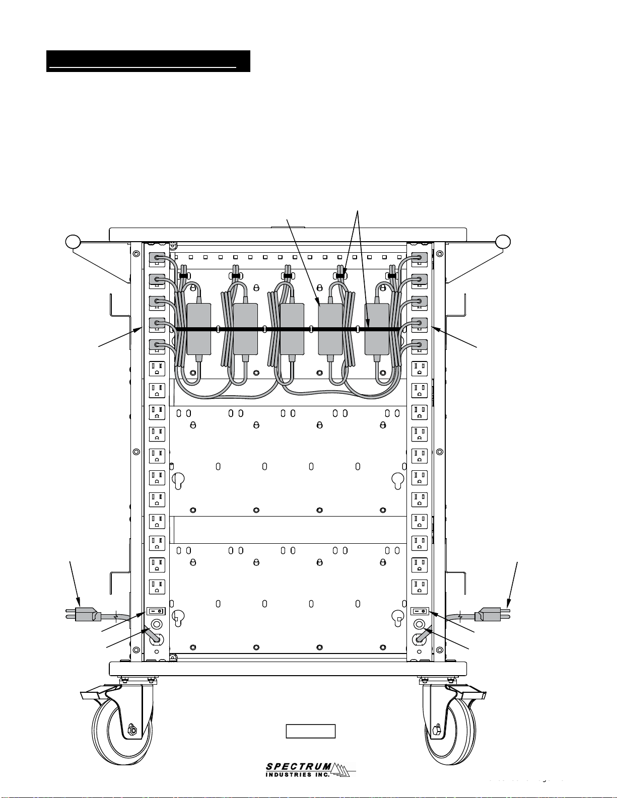
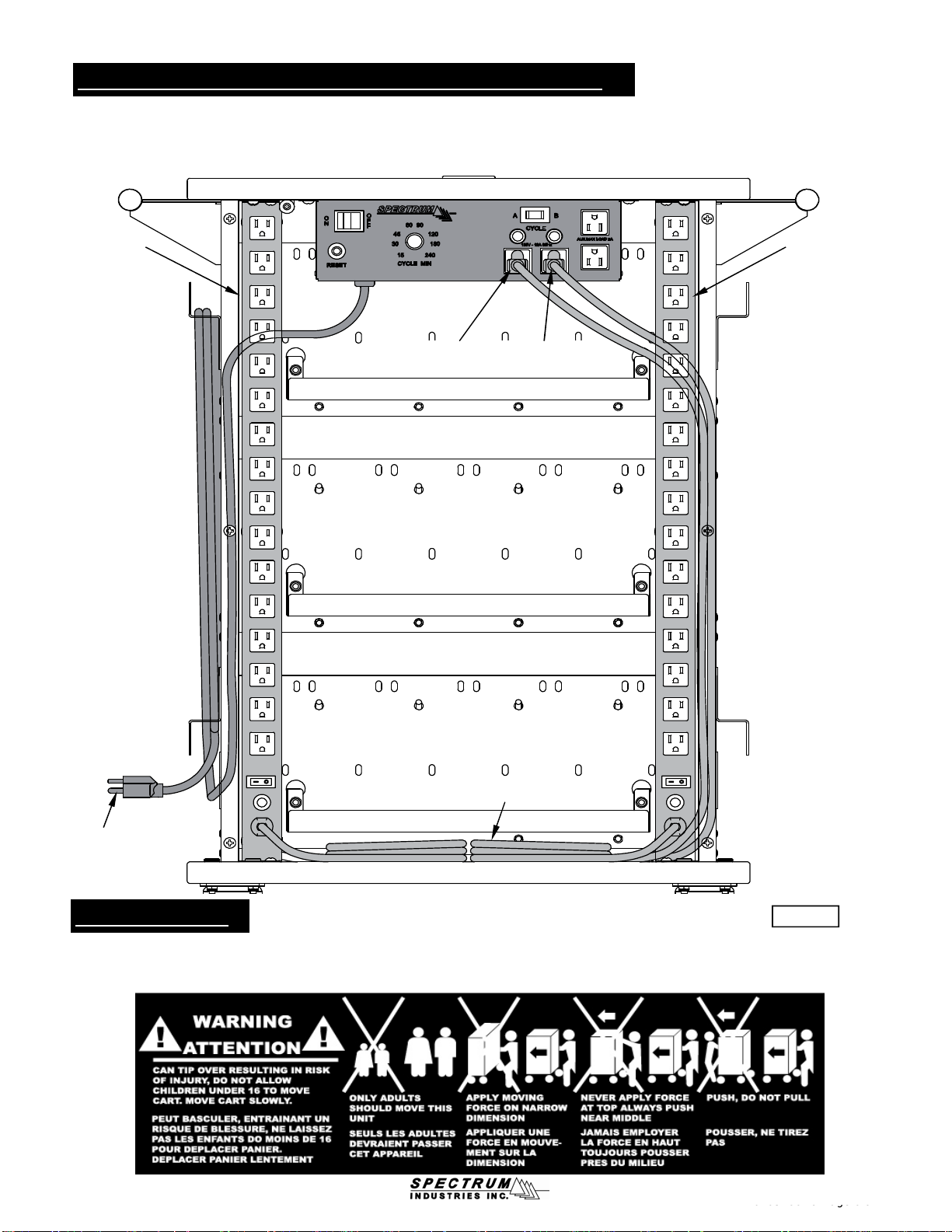
The timer prevents overload by alternating power between both power strips in the cart, providing charging to multiple laptops during
the day. The power strips plug into the outlets labeled 'A' or 'B'.
Th ti t l b dj t d b t 15
240 i t
Thiith b f i t ti illb"ht"bf th
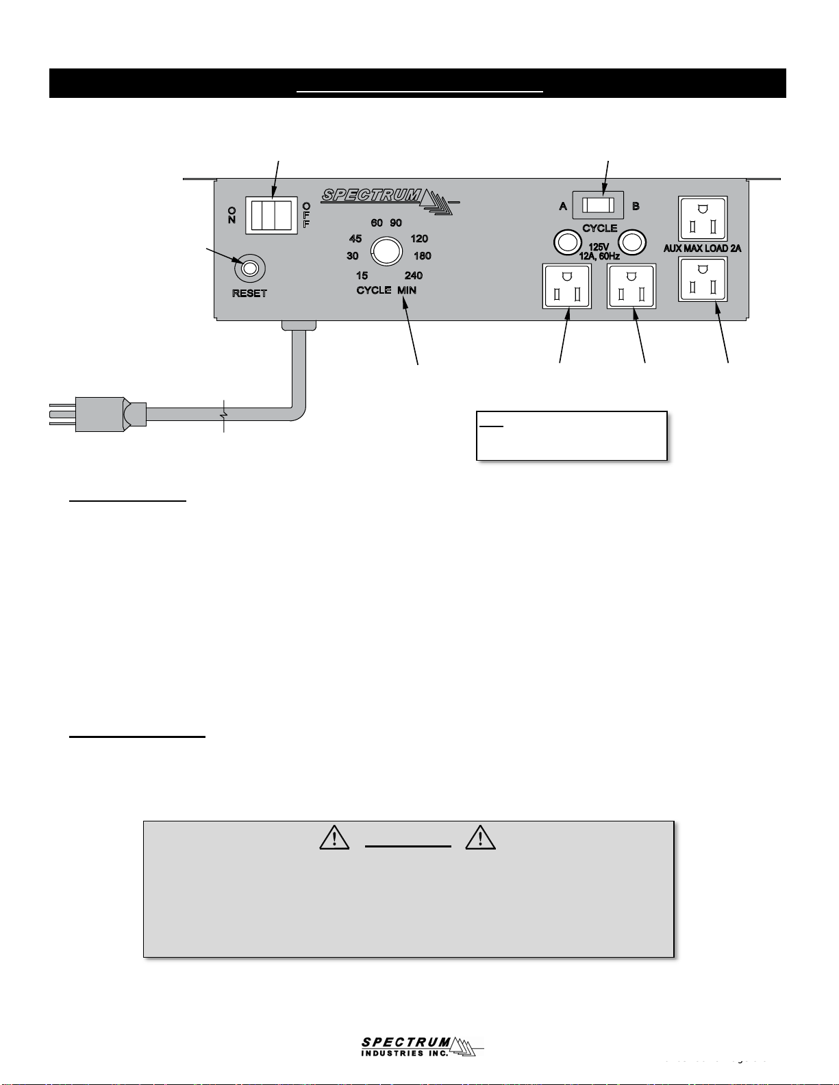
ti
On / Off Switch
(Controls power to timer &
'A' and 'B' outlets)
Timer Control Auxiliary
(constant-power)
2-outlets used for
accessories such
as Wi-Fi routers,
teacher laptops, or
printers
Note:Each laptop cart power strip
needs to be plugged into a separate
outlet ('A' or 'B').
Left (A) power
strip outlet &
indicator
Right (B) power
strip outlet &
indicator
15-amp Reset Button
Power Cord
Cycle Switch
0105788R9 Pa
g
e 9 of 12
CAUTION
• Do not use the auxiliary outlets to charge multiple laptops (use the 'A' and 'B' outlets only.)
Auxiliary outlets are for peripheral use only.
• Total equipment load not to exceed 12-amps per power strip.
• For indoor use only. Do not install or store the unit where it will be exposed to weather.
Keep unit dry.
• For added safety, plug the timer into a grounded three-prong receptacle controlled by a GFI
(Ground Fault Interrupter) circuit breaker.
Th
e
ti
mer con
t
ro
l
can
b
e a
dj
us
t
e
d
b
e
t
ween
15
-
240
m
i
nu
t
es.
Thi
s
i
s
th
e num
b
er o
f
m
i
nu
t
es a power s
t
r
i
p w
ill
b
e
"h
o
t"
b
e
f
ore
th
e
ti
mer
switches to the other power strip. 15 minutes can be used as the default setting, but the time setting will depend on the laptop size,
battery capacity, frequency of laptop use, and the time available for charging between uses. Lower minute settings should be used if
the laptops are being used more frequently.
• To cycle charge both 'A' and 'B' sides, keep the cycle switch in the middle 'Cycle' position, then set the timer control to the
desired cycling increment. After the Side 'A' time expires, the timer will activate Side “B” for the same period of time and will
continue to cycle until the On/Off switch is set to the "OFF" position.
• To manually-override the timer function, and charge side 'A' only, switch the cycle switch from the middle to the 'A' position.
• To manually-override the timer function, and charge side 'B' only, switch the cycle switch from the middle to the 'B' position.
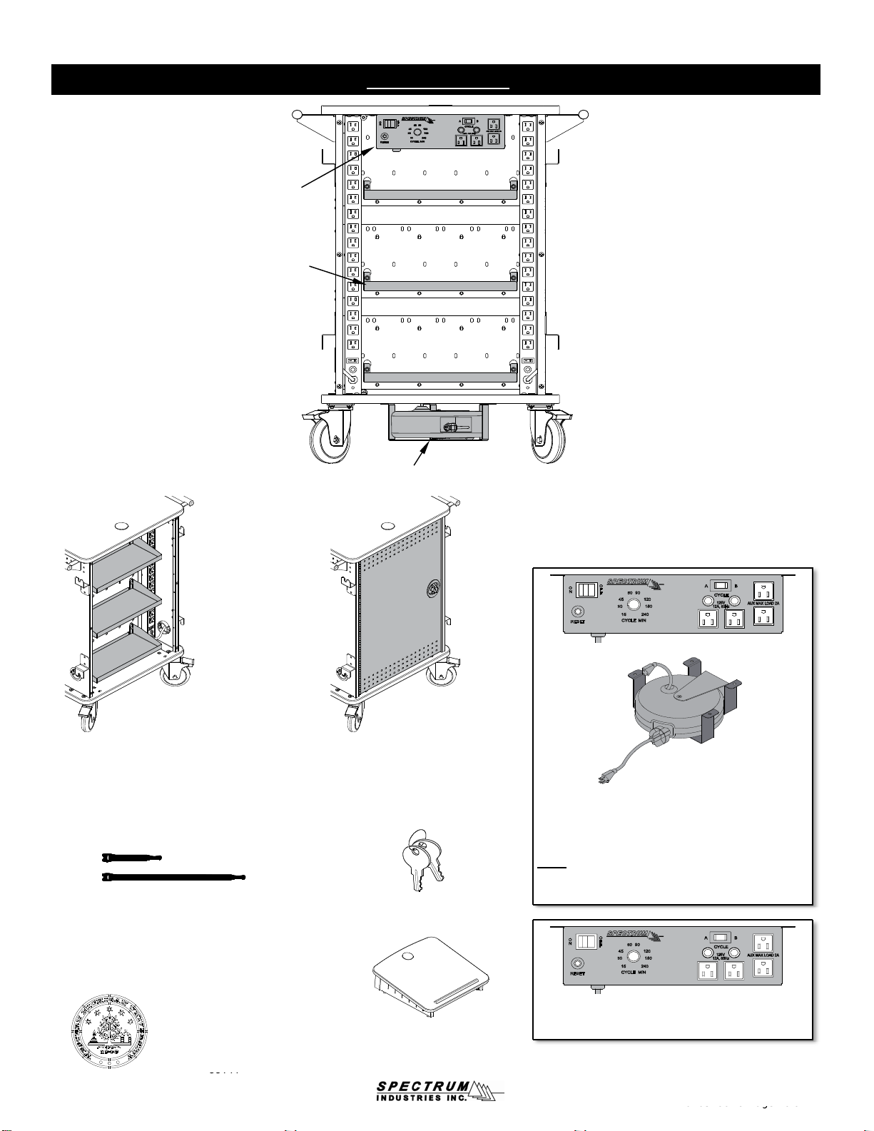
Specifications:
• 12-amp, 120 volt, 60Hz
• 15-240 minute timer
• 20' 14 AWG power cord
0105788R9
Page
9
of
12

mLT-30 Options
Value Cycle Timer
Wire Management Trays
(3 trays included)
Retractable
Cord Reel
0105788R9 Pa
g
e 10 of 12
Wire Management Trays
16"W x 6"D x 2"H
(set of 3 trays holds charging
transformers and cords)
shipping weight: 7 lbs
55316
Replacement Key Set
55142
Lectern Riser
18"W x 1713/16"D
95002
Custom-Cut Logo
(Typical logo location on
rear panel or door)
55141
Velcro® Strap Kit
(16) 3/4" x 12", and (32) 3/4" x 5"
Velcro® Straps
95004
Rear Double-Bolt Locking Door
191/4"W x 3/4"D x 30"H
(replaces rear panel)
shipping weight: 13 lbs
55317
Value Cycle Timer
99035 - Timer only
Value Cycle Timer +
15' Retractable Cord Reel Kit
(factory-installation required)
55324
Note: The cord reel cannot be used by itself on the
mLT-30, and must be used in conjunction with the
optional cycle timer to charge all 30 mini-laptops.
0105788R9
Page
10
of
12
55141

Technical Specs
Construction
●The worksurface and base panel is constructed from 11/16" NAUF (No Added Urea Formaldehyde) composite board with .030 high-
pressure laminate on one face, and a balancing phenolic backer on the opposing face
●16-gauge side panels, shelves, and front door
●All metal components are finished with a scratch-resistant powder coat epoxy
●Worksurface edges are covered with 3mm vinyl
●Each Mini Laptop Cart is factory-assembled, packaged, and shipped on its own skid
(Handle, and cord management brackets to be installed by customer)
Capacity
●Overall dimensions: (See dimensioned drawings)
●Mini Laptop capacity: 30 units
●15 storage slots - 4"W x 121/4"D x 10"H (each slot holds 2 mini laptops)
●Electrical: The cart has two 16-outlet (125V) power strips,
each containing a 15-amp breaker, on/off switch and a 12' nominal 14 AWG,
3-wire power cord. Outlets are accessible from the back of the unit via a
removable panel held in place with 6 Phillips screws or 6 easily removable
thumbscrews (both included.) A separate wall circuit is recommended for
each power strip.
●Meets or exceeds all ANSI-BIFMA test standards
●Features and specifications subject to change without notice
●Unit weight (nominal): 139 lbs
●Shipping weight (nominal): 167 lbs
55315BW
mLT-30 Mini Laptop Cart
w/ balloon wheels
CAUTION
Maximum load not to exceed
60 lbs on worksurface
CAUTION
Maximum load not to exceed
24 lbs on lower shelf
0105788R9 Page 11 of 12
5" balloon wheels
Maximum load not to exceed
24 lbs on lower shelf
CAUTION
Maximum load not to exceed
58 lbs on shelf
0105788R9
Page
11
of
12

Warranty
WE WILL MAKE IT RIGHT FOR YOU!
We guarantee all Spectrum products to be free of all defects in materials and workmanship, for the original owner, for a period of ten years.
Any item deemed defective by Spectrum or the original manufacturer, under normal use conditions, will be repaired or replaced at
Spectrum’s discretion. This warranty applies to all products manufactured and distributed by Spectrum except the products listed below.
DESIGNED FOR INDOOR USE ONLY - Spectrum’s products have been designed and constructed for indoor use only. Moving or using
outdoors, or on excessively rough surfaces, may cause damage to the products and may void the warranty. If an outdoor application is
desired please contact us to discuss potential custom design solutions.
Spectrum is committed to provide complete customer satisfaction. Each of our products are manufactured from the best materials available
and each product is stringently monitored throughout the production process through our P.A.C.E. program (Product Assurance to meet
Customer Expectations).
Our Customer Service Help Line 1-800-235-1262 is ready to provide immediate attention to any questions, comments or concerns. Weare
available to answer your calls Monday through Friday from 7 am to 5 pm CST. In addition your product comments or concerns are welcome
via e-mail at: spectrum@spectrumfurniture.com.
Items that have a varying warranty include, but are not limited to, the following:
• Adjustable Crank/Electric Desk Legs (1 yr)
• Flat Panel Desk Gas Cylinders (1 yr)
• Adjustable Height Chair Parts – including frames, gas cylinders, wood and plastic parts, and control handles (7 yrs)
• Adjustable Height Chair Parts Casters (2 yrs)
• Adjustable Height Chair Upholstery - In-Stock Upholstery (2 yrs)
• Adjustable Height Chair Upholstery - Graded-In Fabrics and C.O.M (no warranty)
• Height Adjustable Columns and Lifts (1 yr)
• General Use Casters (1 yr)
• Electrical – ECA (1 yr)
• Electrical - Power Strips (1 yr)
• Electrical Surge Suppressors (lifetime)
• Electrical - Retractable Power Cords (1 yr)
• Keyboard/Mouse Trays (1 yr)
• Flat Panel Monitor Arm – General Parts (5 yrs)
0105788R9 Pa
g
e 12 of 12
• Flat Panel Monitor Arm
–
Gas Cylinders (2 yrs)
• CRT Monitor Arm (1 yr)
The warranty, as stated above, is effective as of 05/28/2009
0105788R9
Page
12
of
12
Table of contents
Other Spectrum Industries Laptop Accessories manuals