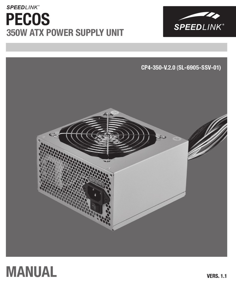
Speed Link PECOS SL-6915-SSV-01 User manual

Manual
PECOS
520W aTX POWER SuPPlY unIT
VERS. 1.1
CP4-520-V.2.0 (Sl-6915-SSV-01)

2
DE
Haftungsausschluss
Die Jöllenbeck GmbH übernimmt keine Haftung für Schäden am Produkt oder Verletzungen von
Personen aufgrund von unachtsamer, unsachgemäßer, falscher oder dem Herstellerzweck
nicht entsprechender Verwendung des Produkts. Unter keinen Umständen haftet die Jöllenbeck
GmbH für tatsächlich entstandene, mittelbare, unmittelbare oder Folgeschäden, Datenver-
lust, Produktionsausfälle, Einkommensausfall oder entgangenen Gewinn, Sachschäden und
Ersatzansprüche Dritter. Sie sollten vor dem Formatieren und Partitionieren der Festplatte eine
vollständige Sicherheitskopie Ihres Systems erstellen.
Störungen
Unter Einwirkung von starken statischen, elektrischen oder hochfrequenten Feldern (Funkan-
lagen, Mobiltelefonen, Mikrowellen-Entladungen) kann es zu Funktionsbeeinträchtigungen des
Gerätes (der Geräte) kommen. Versuchen Sie in diesem Fall, die Distanz zu den störenden
Geräten zu vergrößern.
Entsorgung
Die Kennzeichnung auf dem Produkt bzw. in der dazugehörigen Literatur gibt an, dass es
nach seiner Lebensdauer nicht zusammen mit dem normalen Haushaltsmüll entsorgt werden
darf. Entsorgen Sie dieses Gerät bitte getrennt von anderen Abfällen, um der Umwelt bzw.
der menschlichen Gesundheit nicht durch unkontrollierte Müllbeseitigung zu schaden. Recyceln
Sie das Gerät, um die nachhaltige Wiederverwertung von stofichen Ressourcen zu fördern.
Private Nutzer sollten den Händler, bei dem das Produkt gekauft wurde, oder die zuständigen
Behörden kontaktieren, um in Erfahrung zu bringen, wie sie das Gerät auf umweltfreundliche
Weise recyceln können. Gewerbliche Nutzer sollten sich an Ihren Lieferanten wenden und die
Bedingungen des Verkaufsvertrags konsultieren. Dieses Produkt darf nicht zusammen mit
anderem Gewerbemüll entsorgt werden.
Technischer Support
Bei Fragen oder Problemen steht Ihnen unser technischer Support zur Verfügung.
Schauen Sie auf die Webseite http://www.speedlink.com oder schreiben Sie eine E-Mail an:
INFORMATIONEN

3
DE
Stromversorgung
Überprüfen Sie vor dem Anschließen die Versorgungsspannung. Die Stromquelle, mit der das
Netzteil betrieben wird, muss den auf dem Etikett angegebenen Werten entsprechen. Benutzen
Sie das Netzteil nie für Geräte, deren Spannung größer ist als die für das Netzteil vorgesehene,
Sie laufen Gefahr, Netzteil und Gerät zu beschädigen.
Für den Betrieb dieses Geräts sollte sich die Steckdose in der Nähe benden und leicht
zugänglich sein.
Dieses Gerät ist erst vollständig vom Strom getrennt, wenn der Netzstecker gezogen ist.
Reinigung
Schalten Sie das Netzteil vor dem Reinigen bitte aus und trennen Sie es vom Stromnetz. Reini-
gen Sie das Gerät bitte nur von außen und verwenden Sie dazu ein weiches, trockenes Tuch.
Fehlerbeseitigung/Reparatur
Um der Gefahr eines Stromschlages vorzubeugen, öffnen Sie das Netzteilgehäuse nicht. Dieses
Produkt enthält keine austauschbaren Teile. Versuchen Sie nicht, das Gerät selbst zu warten
oder zu reparieren. Überlassen Sie jegliche Reparatur dem zuständigen Fachpersonal. Nehmen
Sie keine Veränderungen am Gerät vor. Dadurch verlieren Sie jegliche Garantieansprüche.
Feuchtigkeit/Wärmequellen
Verwenden Sie das Gerät nicht in der Nähe von Wasser (z. B. Waschbecken, Badewannen etc.),
und halten Sie es von Feuchtigkeit, tropfenden oder spritzenden Flüssigkeiten sowie Regen
fern. Setzen Sie das Gerät keinen hohen Temperaturen, hoher Luftfeuchtigkeit oder direktem
Sonnenlicht aus.
WICHTIGE SICHERHEITSHINWEISE

4
DE
Lieferumfang: • 1 × Netzteil
• 1 × Netzkabel
• 1 × Bedienungsanleitung
• 4 × Schrauben
• 4 × Kabelbinder
• 1 × PATA/SATA-Adapter
Modellbeschreibung: CP4-520-V.2.0 – 520 Watt PC Power Supply (SL-6915-SSV-01)
Bauform/Standard: ATX/ATX 2.3
Anschlüsse: 1 × 20/24-pin Main ATX (500 mm), 1 × 4-pin P4, 3 × IDE/PATA, 3 × SATA
(plus 1 × PATA/SATA-Adapter), 1 × FDD, 1 × 6-pin PCIe
Kühlung: 120-mm-Lüfter (temperaturgesteuert)
Leistung: 520 W
Eingang (DC): 200-240 V, 47-53 Hz, 6 A
PFC: Passiv-PFC
Abmessungen: 148 × 140 × 86 mm
Gewicht: 1410 g
Zertikate: TÜV, CE, RoHS nach 2002/95/EC
Hersteller: ACOS GmbH
Kulemannstieg 34
D-22457 Hamburg
Vertrieb: Jöllenbeck GmbH
Kreuzberg 2
D-27404 Weertzen
TECHNISCHE DATEN
+3,3 V
24 A
Ausgangsleistung +5 V
21 A
+12 V
36 A
5 V SB
2,5 A
-12V
0,3 A

5
DE
Wichtiger Hinweis:
Die Stromversorgung des Mainboards kann abhängig von Hersteller und Produkt variieren.
Bitte greifen Sie für detaillierte Angaben und Anweisungen auf die Bedienungsanweisung Ihres
Mainboards zurück.
Sollten Sie keine Fachkenntnisse für den Einbau besitzen, so lassen Sie ihn bitte von einer
Fachkraft oder einer entsprechenden Fachwerkstatt vornehmen!
Ausbau des alten Netzteils
Schalten Sie Ihr Netzteil am Netzschalter aus und trennen Sie den Rechner vom Stromnetz.
Warten Sie ungefähr zwanzig Minuten, damit sich der Reststrom entladen und das Netzteil
abkühlen kann. Dann öffnen Sie den Computer, indem Sie die linke Seitenwand abschrauben.
Als nächstes trennen Sie alle Verbindungen vom alten Netzteil zu den verschiedenen
Komponenten wie z.B. dem Motherboard, der Festplatte, der Grakarte etc. Danach lösen Sie die
Schrauben, mit denen das Netzteil an der Rückseite des Rechners befestigt ist, und nehmen
es vorsichtig heraus.
Einbau des neuen Netzteils
Nun können Sie das neue Netzteil in die Halterung schieben. Achten Sie dabei darauf, dass das
eine Lüftungsgitter zur Rechnerinnenseite nicht versperrt ist und die heiße Luft aus dem Compu-
terinnenraum angesaugt und nach außen weggeleitet werden kann.
Dann ziehen Sie die Schrauben an der Rückseite des Rechners wieder fest.
Anschluss des Netzteils
Nun können Sie damit beginnen, das Netzteil an die Komponenten anzuschließen. Bitte
versuchen Sie nie mit Gewalt einen Stecker mit einem Anschluss zu verbinden.
Netzteil und Hardware-Komponenten tragen dadurch Schäden davon, die nicht unter unsere
Garantieleistung fallen.
INSTALLATION

6
DE
20+4-pol. MAIN-Stromanschluss – Motherboard
4-pol. +12V-AUX/P4-Stromanschluss – 12V-AUX/P4
5-pol. S-ATA-Stromanschluss – SATA-Festplatten,
SATA-CD-ROM-/DVD-Laufwerke/ Brenner
6-pol. PCI Express-Stromanschluss – PCI Express Grakkarten
4-pol. Peripheriegeräteanschluss – IDE-Festplatten, CD-ROM-Laufwerke/Brenner,
DVD-Laufwerke/Brenner, AGP-Grakkarten
4-pol. Floppy-Anschluss – Disketten-/Floppy-Laufwerk
Zuerst wird Hauptstromstecker (1) des Netzteils an der Hauptplatine, dem sogenannten
Motherboard angeschlossen. Einige Motherboards benötigen dazu einen 20-pol.-Anschluss,
andere einen 24-pol.-Anschluss. Für diesen Fall verfügt das Pecos 520 Watt über einen
20-pol.-Anschluss mit 4-Pol-Zusatzstecker. Diese 4-pol.-Erweiterung von 20- auf 24-poligen
Kombistecker darf nicht in die weit entlegene 12V-AUX/P4-Buchse gesteckt werden. Sie gehört
entweder in die 24-polige Extended ATX Buchse oder bleibt im Falle von ATX 20-polig
ungenutzt.
Für den 12V-AUX-Anschluss gibt es einen eigenen 4-pol.-+12V-Stecker (2), der z.B. dadurch zu
erkennen ist, dass er nur über zwei schwarze und zwei gelbe Kabel verfügt.
Der 5-pol. SATA-Stromanschluss (3) ist ein sehr acher, schwarzer Stecker, der der Verbindung
des Netzteils mit einer SATA-Festplatte oder SATA-CD-ROM-/DVD-Laufwerken oder -Brennern
dient.
1 2 3
1
2
3
4
5
6
4 5 6

7
DE
Der 6-pol. PCI Express-Stromanschluss (4) ist für PCI Express Grakkarten vorgesehen,
bestimmte AGP-Grakkarten sowie IDE-Festplatten und CD-ROM-und DVD-Laufwerke sowie
-Brenner benötigen hingegen einen 4-pol. Peripherie-Stromanschluss (5).
Verfügt Ihr Rechner über ein Disketten-/Floppy-Laufwerk, verbinden Sie dieses bitte über den
4-pol.-FDD (6) mit dem Netzteil.
Inbetriebnahme des Netzteils
Überprüfen Sie alle Kabelverbindungen und stellen Sie sicher, dass alle Geräte richtig
verbunden wurden. Stecken Sie dann das Netzkabel in Netzteil und Steckdose. Legen Sie den
Netzschalter von „0“ auf „I“ um. Lässt sich der Rechner nun problemlos hochfahren, haben Sie
alle Geräte korrekt angeschlossen und die Installation des Netzteils ist beendet.
Pol Funktion Farbe Pol Funktion Farbe
1 +3,3 V Orange 13 +3,3 V Orange
2 +3,3 V Orange +3,3 Vs Braun
3COM Schwarz 14 -12 V Blau
4 +5 V Rot 15 COM Schwarz
5COM Schwarz 16 PS-ON Grün
6 +5 V Rot 17 COM Schwarz
7COM Grau 18 COM Schwarz
8PWR OK Blau 19 COM Schwarz
9 +5 VSB Gelb 20 --- ---
10 +12 V Gelb 21 +5 V Rot
11 +12 V Orange 22 +5 V Rot
12 +3 V 23 +5 V Rot
24 COM Schwarz
20+4 pol. MAIN-Stromanschluss
KABELDIAGRAMME
1
13
12
24

8
DE
Pol Funktion Farbe
1 +3,3 V Orange
2COM Schwarz/Schwarz
3 +5 V Rot/Rot
4COM Schwarz/Schwarz
5 +12 V Gelb/Gelb
5-pol. SATA-Stromanschluss
Pol Funktion Farbe Pol Funktion Farbe
1 +12 V Gelb 1COM Schwarz
2 +12 V Gelb 2COM Schwarz
3 +12 V Gelb 3COM Schwarz
6-pol. PCI Express-Stromanschluss
1
4
4-pol. +12V-AUX/P4-Stromanschluss
1
3
Pol Funktion Farbe
1COM Schwarz
2COM Schwarz
3 +12 V Gelb
4 +12 V Gelb

9
DE
4-pol. Peripheriegeräteanschluss
Pol Funktion Farbe
1 +12 V Gelb/Gelb
2COM Schwarz/Schwarz
3COM Schwarz/Schwarz
4 +5 V Rot/Rot
Pol Funktion Farbe
1 +12 V Gelb
2COM Schwarz
3COM Schwarz
4 +5 V Rot
4-pol. Floppy-Anschluss
Sollte sich der Rechner nicht hochfahren lassen, ergreifen Sie bitte die folgenden Maßnahmen.
• Stellen Sie sicher, dass der Netzschalter auf „I“ gestellt ist.
• Schauen Sie nach, ob das Netzkabel korrekt mit dem Netzteil und der Steckdose verbunden ist.
• Überprüfen Sie, ob alle Komponenten einwandfrei an das Netzteil angeschlossen sind.
• Schalten Sie das Netzteil aus, warten Sie ein paar Sekunden und schalten Sie es dann
wieder ein.
• Sollte der Rechner trotzdem nicht hochgefahren werden können, wenden Sie sich bitte an
Fachpersonal. Öffnen Sie unter keinen Umständen das Netzteil und nehmen Sie auch sonst
keine Änderungen an dem Gerät vor!
FEHLERBEHEBUNG

10
En
Disclaimer of liability
Jöllenbeck GmbH accepts no liability whatsoever for any product deciencies or injuries caused
to people due to careless, improper or incorrect use of the product or use of the product for
purposes not recommended by the manufacturer. Under no circumstances will Jöllenbeck GmbH
be liable for actually incurred, indirect, direct or consequential damages, loss of data, losses of
production, loss of income or lost prot, damage to property and third-party claims for
compensation. You should make a full backup of your system before formatting and partitioning
the hard drive.
Interference
Operation of the device (the devices) may be affected by strong static, electrical or high-
frequency elds (radio installations, mobile telephones, microwave discharges). If this occurs,
try increasing the distance between the devices that are causing interference.
Disposal
The markings on the product and on the associated literature show that this product must not be
disposed of together with normal household waste at the end of its useful life. Please dispose of
this device separately from other waste in order not to cause harm to the environment or human
health through uncontrolled refuse disposal. Recycle the device to facilitate the sustainable
recycling of material resources. Private users should contact the dealer from whom the product
was bought, or the authorities responsible for recycling, to nd out how to recycle the device in
an environmentally friendly way. Commercial users should ask their suppliers and consult the
sales contract terms. This product must not be disposed of together with other commercial waste.
Technical support
Our Technical Support team is there for you in the event of any questions or problems. Visit our
website: http://www.speedlink.com or send an e-mail to: [email protected]
INFORMATIONS

11
En
Power supply
Check the supply voltage before connecting. The power source used to power the power supply
unit must correspond to the values stated on the label. Never use the power supply unit to power
devices whose required voltage is lower than the one specied on the power supply unit as you
risk damaging both the power supply unit and the device.
As this device is mains powered, place it near an easily accessible AC outlet.
This device will only be completely disconnected from the mains once it has been unplugged.
Cleaning
Switch the power supply unit off and unplug it from the mains supply before cleaning it. Only
clean the outside of the device and use a soft, dry cloth to do so.
Troubleshooting/repairs
To avoid the risk of electric shock, do not open the power supply unit casing. This product does
not contain any interchangeable parts. Do not attempt to service or repair the product yourself;
leave any repairs to qualied personnel. Do not attempt to modify the product in any way as doing
so will invalidate the warranty.
Moisture/heat
Do not operate the device near water (e.g. sinks, baths, etc.) and keep it away from moisture,
areas where liquids are likely to drip or be sprayed as well as rain. Do not expose the product to
high temperatures, high humidity or direct sunlight.
IMPORTANT SAFETY NOTES

12
En
What’s included: • 1 × PSU
• 1 × Mains cable
• 1 × User manual
• 4 × Screws
• 4 × Cable ties
• 1 × PATA/SATA adapter
Model description: CP4-520-V.2.0 – 520 Watt PC Power Supply (SL-6915-SSV-01)
Form factor: ATX/ATX 2.3
Connectors: 1 × 20/24-pin main ATX (500 mm), 1 × 4-pin P4, 3 × IDE/PATA,
3 × SATA (plus 1 × PATA/SATA adapter), 1 × FDD, 1 × 6-pin PCIe
Ventilation: 120mm fan (temperature controlled)
Total power: 520W
Input voltage (AC): 200-240V, 47-53Hz, 6A
PFC: Passive PFC
Dimensions: 148 × 140 × 86mm
Weight: 1410g
Certicates: TÜV, CE, RoHS pursuant to 2002/95/EC
Manufacturer: ACOS GmbH
Kulemannstieg 34
D-22457 Hamburg
Germany
Distributor: Jöllenbeck GmbH
Kreuzberg 2
D-27404 Weertzen
Germany
Power Output
TECHNICAL INFORMATION
+3.3V
24A
+5V
21A
+12V
36A
5VSB
2.5A
-12V
0.3A

13
En
Important:
The mainboard’s power supply requirements may vary depending on the manufacturer and
product. Please refer to your mainboard’s operating instructions for detailed specications and
instructions. If you do not have the necessary level of technical knowledge to install the device,
please arrange for an expert or specialist company to install it.
Removing the old power supply unit
Set the power switch on the power supply unit to off and unplug the computer from the
mains socket. Wait around 20 minutes to allow any residual power to discharge and to allow the
power supply unit to cool down.
Following that, open the computer by unscrewing the left side panel. Now disconnect all
connections between the old power supply unit and the various components such as the
motherboard, the hard drive and graphics card, etc.Then unscrew the screws that are used to
secure the power supply unit to the back of the computer and carefully remove the power
supply unit.
Installing the new power supply unit
You can now slot the new power supply unit into the mount. When doing so, make sure that the
single ventilation grill on the inside of the computer is not blocked so that hot air from inside the
computer can be sucked in and vented to the outside.
After that, tighten the screws on the back of the computer again.
Connecting the power supply unit
You can now start connecting the components to the power supply unit. Never try and plug a
connector into a socket using force as this may result in the power supply unit and hardware
components sustaining damage which is not covered by our warranty.
INSTALLATION

14
En
20+4-pin MAIN power connector – motherboard
4-pin +12V AUX/P4 power connector – 12V AUX/P4
5-pin SATA power connector – SATA hard drives,
SATA CD-ROM/DVD drives/writers
6-pin PCI Express power connector – PCI Express graphics cards
4-pin peripheral device connector – IDE hard drives, CD-ROM drives/writers,
DVD drives/writers, AGP graphics cards
4-pin oppy connector – disc/oppy drives
First, connect the main power connector (1) on the power supply unit to the mother board.
Some motherboards require a 20-pin connector, others a 24-pin connector. For this reason the
Pecos 520W has a 20-pin connector with an additional 4-pin connector. This 4-pin 20 to 24-pin
combo connector extender must not be plugged into the 12V AUX/P4 socket. It should either be
plugged into the 24-pin extended ATX socket or, if an ATX 20-pin socket is present, must be left
unplugged.
There is a dedicated 4-pin +12V plug (2) for the 12V AUX connector which is easy to identify as it
only has two black and two yellow cables.
The 5-pin SATA power connector (3) is a very at, black connector which is used to connect the
power supply unit to a SATA hard drive or SATA CD-ROM/DVD drives or writers.
The 6-pin PCI Express power connector (4) is intended for PCI Express graphics cards. Certain
AGP graphics cards as well as IDE hard drives and CD-ROM and DVD drives and writers require
1 2 3
1
2
3
4
5
6
4 5 6

15
En
a 4-pin peripheral power connector (5).
If your computer has a disc/oppy drive, please connect this to the power supply unit using the
4-pin FDD connector (6).
Powering on the power supply unit
Check all cable connections and make sure that all devices have been connected correctly. Now
plug the power cord into the power supply unit and a mains socket. Set the switch on the power
supply unit from ‘0’ to ‘I’. If the computer boots correctly, you have connected all devices correctly
and the process of installing the power supply unit is now complete.
Pin Function Colur Pin Function Colour
1 +3.3V Orange 13 +3.3V Orange
2 +3.3V Orange +3.3Vs Brown
3COM Black 14 -12V Blue
4 +5V Red 15 COM Black
5COM Black 16 PS-ON Green
6 +5V Red 17 COM Black
7COM Grey 18 COM Black
8PWR OK Blue 19 COM Black
9 +5VSB Yellow 20 --- ---
10 +12V Yellow 21 +5V Red
11 +12V Orange 22 +5V Red
12 +3V 23 +5V Red
24 COM Black
20+4-pin MAIN power connector
CABLE DIAGRAMS
1
13
12
24

16
En
Pin Function Colour
1 +3.3V Orange
2COM Black/Black
3 +5V Red/Red
4COM Black/Black
5 +12V Yellow/Yellow
5-pin SATA power connector
Pin Function Colour Pin Function Colour
1 +12V Yellow 1COM Black
2 +12V Yellow 2COM Black
3 +12V Yellow 3COM Black
6-pin PCI Express power connector
1
4
4-pin +12V AUX/P4 power connector
1
3
Pin Function Colour
1COM Black
2COM Black
3 +12V Yellow
4 +12V Yellow

17
En
4-pin peripheral device connector
Pin Function Colour
1 +12V Yellow/Yellow
2COM Black/Black
3COM Black/Black
4 +5V Red/Red
Pin Function Colour
1 +12V Yellow
2COM Black
3COM Black
4 +5V Red
4-pinoppyconnector
If the computer doesn’t boot correctly please take the following steps:
• Make sure the power switch is set to ‘I’.
• Check to see if the power cord has been correctly plugged into the power supply unit and the
mains socket.
• Check to see if all components are correctly connected to the power supply unit.
• Switch the power supply unit off, wait a few seconds, and then switch it back on again.
• If the computer still won’t boot despite taking these steps, please refer to a specialist. You
should neither attempt to open the power supply unit nor modify the device!
TROUBLESHOOTING

18
FR
Clause d’exclusion de responsabilité
La société Jöllenbeck GmbH décline toute responsabilité en cas de dégradations du produit ou
de blessures corporelles dues à une utilisation du produit inconsidérée, incorrecte, erronée ou
contraire aux instructions données par le fabricant. La société Jöllenbeck GmbH n’est en aucun
cas responsable des dommages réels, directs, indirects ou consécutifs, des pertes de données,
des interruptions de la production, des pertes de revenus ou manques à gagner, des
dégradations matérielles et des demandes de dommages et intérêts de tiers. Avant de formater
et de partitionner le disque dur, effectuez une sauvegarde complète de votre système.
Pannes
La présence de champs statiques, électriques ou à haute fréquence intenses (installations
radio, téléphones mobiles, décharges de micro-ondes) peut perturber le bon fonctionnement
de l‘appareil (ou des appareils). Dans ce cas, essayez d‘éloigner les appareils à l’origine des
perturbations.
Élimination
Le marquage gurant sur ce produit et sur les documents correspondants indique qu’il ne doit
pas être placé avec les ordures ménagères courantes à l’issue de sa durée de vie. Veuillez
séparer cet appareil des autres déchets pour ne pas nuire à l’environnement et à la santé des
personnes par une élimination non contrôlée des déchets. Recyclez l’appareil pour encourager la
récupération durable des ressources matérielles. Les utilisateurs privés peuvent contacter le
vendeur auprès duquel ils ont acheté le produit ou les autorités compétentes pour savoir
comment recycler l’appareil de manière respectueuse de l’environnement. Les utilisateurs
professionnels doivent s’adresser à leurs fournisseurs et consulter les conditions qui gurent
dans le contrat de vente. Ce produit ne doit pas être placé avec d’autres déchets industriels.
Assistance technique
En cas de questions ou de problèmes, notre service d‘assistance technique se tient à votre
disposition. Consultez le site http://www.speedlink.com ou envoyez un message par e-mail à :
INFORMATIONS

19
FR
Alimentation électrique
Avant de procéder au raccordement, vériez la tension d’alimentation. La source électrique à
laquelle est raccordé le bloc d’alimentation doit correspondre aux valeurs indiquées sur
l’étiquette. N’utilisez jamais le bloc d’alimentation pour des appareils d’une tension supérieure à la
tension prévue pour le bloc d’alimentation ; vous risqueriez d’endommager le bloc d’alimentation
et l’appareil.
La prise de courant doit se trouver à proximité et être aisément accessible.
Cet appareil n‘est complètement hors tension que lorsque la prise secteur est débranchée.
Nettoyage
Éteignez le bloc d’alimentation avant de nettoyer l’appareil et débranchez-le du secteur. Ne
nettoyez l’appareil qu’extérieurement en utilisant pour cela un chiffon doux et sec.
Élimination des erreurs/Réparations
Pour prévenir tout risque d’électrocution, n’ouvrez pas le boîtier du bloc d’alimentation. Ce produit
ne comprend pas de pièces échangeables. N’essayez pas de réparer ou d’entretenir vous-
même l’appareil. Conez tous les travaux de maintenance à un technicien qualié. N’apportez
aucune modication à l’appareil. Cela annulerait toute possibilité de recours en garantie.
Humidité/Sources de chaleur
N’utilisez pas l’appareil à proximité d’eau (par exemple auprès d’un lavabo, d’une baignoire, etc.)
et gardez-le à l’abri de l’humidité (éclaboussures, égouttement, pluie). N’exposez pas l’appareil
à des températures élevées, à un air très humide ou au rayonnement direct du soleil.
CONSIGNES DE SÉCURITÉ IMPORTANTES

20
FR
Éléments fournis : • 1 × bloc d‘alimentation
• 1 × câble d’alimentation
• 1 x mode d’emploi
• 4 x vis
• 4 × attache-câbles
• 1 × adaptateur PATA/SATA
Modèle : CP4-520-V.2.0 – 520 Watt PC Power Supply (SL-6915-SSV-01)
Forme/standard : ATX/ATX 2.3
Branchements : 1 × Main ATX 20/24 broches (500 mm), 1 × P4 4 broches, 3 × IDE/PATA,
3 × SATA (plus 1 × adaptateur PATA/SATA), 1 × FDD, 1 × PCIe 6 broches
Refroidissement : Ventilateur 120 mm (avec contrôle de la température)
Puissance : 520 W
Entrée (CA) : 200-240 V, 47-53 Hz, 6 A
PFC : PFC passif
Dimensions : 148 × 140 × 86 mm
Poids : 1410 g
Certicats: TÜV, CE, RoHS selon 2002/95/CE
Fabricant : ACOS GmbH
Kulemannstieg 34
22457 Hamburg – Allemagne
Distribution : Jöllenbeck GmbH
Kreuzberg 2
27404 Weertzen – Allemagne
Sortie (CC)
CARACTÉRISTIQUES TECHNIQUES
+3,3 V
24 A
+5 V
21 A
+12 V
36 A
5 V SB
2,5 A
-12V
0,3 A
This manual suits for next models
1
Table of contents
Languages:
Other Speed Link Power Supply manuals
