SPEED-O-CONTROLS ST 515 User manual
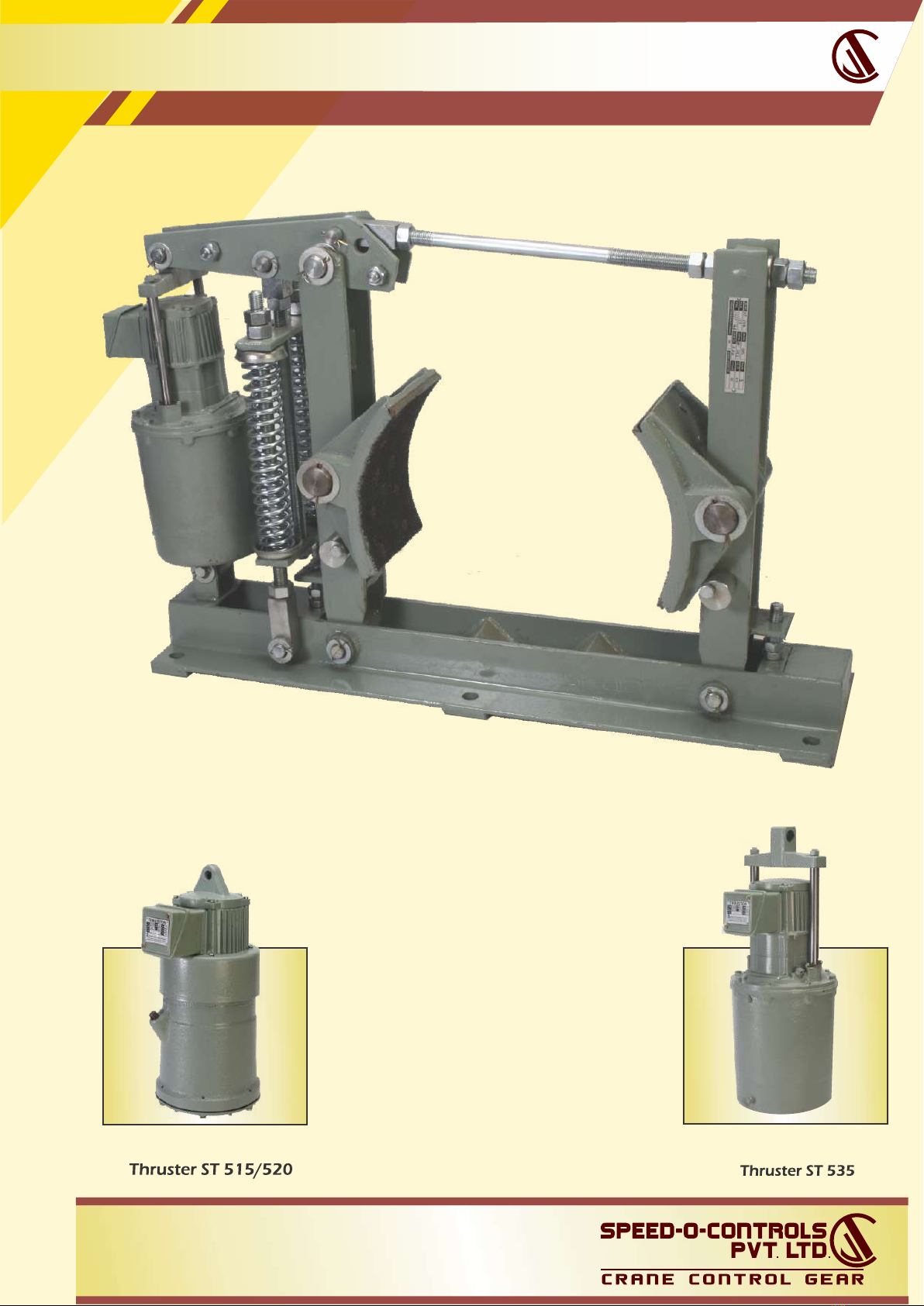
MILL DUTY THRUSTER BRAKES
ELECTRO HYDRAULIC ELECTRO HYDRAULIC
Visit us at :
www.speedocontrols.com
www.socremote.com
H. O. Unit -I : C-15/16, Nand Jyot
Industrial Estate, Andheri-Kurla
Road, Mumbai - 400072 ,
Tel : (022) 42469700/730
E-mail : [email protected]
Unit - II: Plot No. 4912, G. I. D. C.,
Phase IV, Vatva,
Ahmedabad - 382445
Tel.
:
(079) 68169700/702/712

MILL DUTY THRUSTER BRAKES
INSTALLING BRAKE IN POSITION
INSTALLING THRUSTER ON BRAKE
1
2
17
8
9
6
7
14
11
12
13
15
17
3
16
4
5
18
5
INTRODUCTION
CONSTRUCTION AND OPERATION
Thruster brake is a device to retard the speed of moving machinery
and to stop it accurately to the desired position. The braking force is
applied to the brake shoes by a pre-streesed compression spring.
The shoe press on the rotating brake drum retarding its speed and
finally stopping it. Other release device like pneumatics /hydraulic
cylinder or manual release arrangements can be offered on request.
To insert the brake in position, the brake shoes are to be
taken apart to clear the drum diameter. To don this,
slacken the spring settling nut and the tie-rod nut in the 14 9
side arm and pull it slightly. This increase the distance between
the brake shoes. Insert the brake on the foundation bolts.
Adjust shoes by setting screws and position them on brake17
drum. Re-tighten the setting bolt and the tie-rod nut.9
Tighten the foundation bolt 18 .
The thruster tank is to be filled with sufficient quantity of oil
as mentioned in the Thruster dimension Table. To mount the
thruster on the brake, remove one side splits pins on the
thruster hinge pins. in the base frame of brake and lever .15 12
Remove both pins and re-insert them after positioning the
thruster on the pin holes in the base and the lever of the base
Replace both split pins. Check that the thruster movement is
unobstructed when the crane lever is pulled manually and
the thrust rod of the thruster is free to move. Open the terminal
box cover of the thruster and connect power supply cables to
the three terminals on the terminal plate inside the terminal box.
Terminate the earthing lead on the earth terminal plate inside
the te rmi nal pr ovi ded on the thruster or br ake .
Replace the terminal box cover on the terminal box.The thruster
is ready for operation.
ALIGNING AND SETTING OF BRAKE
TECHNICAL DATA
Next, align the brake shoes with the diameter and the surface of
the brake drum and adjust the lock nuts 9 on the tie-rod such
that shoes grip the brake drum equally. Energize the power
cables, this will cause the thrust rod of the thruster to move up
and the shoes release th brake drum. Adjust the gap between
the drum and shoes to 0.3 to 0.5mm (with feeler gauge) equally
by adjusting the setting bolts 17 on both arms. For equal and
uniform liner wear it is necessary that the shoes and the arms
move equally. Ensure the brake drum is free to rotate when the
brake is released.
ADJUSTING BRAKING TORQUE
To adjust the braking torque to the desired value, the
pre-loadingof the compression spring is to be done by top 13
nuts on the spring tie rod. To increase torque, turn nut 14
clockwise. For most applications, braking torque of about
150 to 250% of rated torque of the drive motor is sufficient.
Colour RAL 7021
POWDER COATING
Asbestos Free Liner
Lining Wear Indicator
Open Brake Limit Switch
Manual Opening & Locking
System
LAF
OL
LWI
MS
A thruster shoe brake has a pair of shoes which are lined up with1
friction pads 2 the shoes are hinged on main arm and side arm 3 4
of the brake, each of them have hinge pin fitted in the base. Both5
arms are connected to each other on top by a tie rod .A hinge in 6 7
the main arm and the swivel block lock nut in the side arm, and8 9
the other end is fixed on top clevis of the thruster by a hinge pin11
.A brake spring ,is fixed on the main arm and is pre - loaded 12 13
by a locknut on the lever. The pre-tension in this spring decides14
the braking torque The thruster is fitted on the base by a hinge pin.
When the thruster is not energized, the brake shoes are pressed on
the brake drum 16 fitted on the drive motor shaft and is braked
under the effect of braking force provided by spring. In such
condition, the brake is applied, and the drum cannot rotate. When
the thruster motor is energized , the lifting force provided by thruster
lifts up the crank lever causing the arms and the shoe to move
away and the brake is released. The spring is compressed and
braking energy is stored for the next cycle.
OPTIONAL
Visit us at :
www.speedocontrols.com
www.socremote.com
H. O. Unit -I : C-15/16, Nand Jyot
Industrial Estate, Andheri-Kurla
Road, Mumbai - 400072 ,
Tel : (022) 42469700/730
E-mail : [email protected]
Unit - II: Plot No. 4912, G. I. D. C.,
Phase IV, Vatva,
Ahmedabad - 382445
Tel.
:
(079) 68169700/702/712

MILL DUTY THRUSTER BRAKES
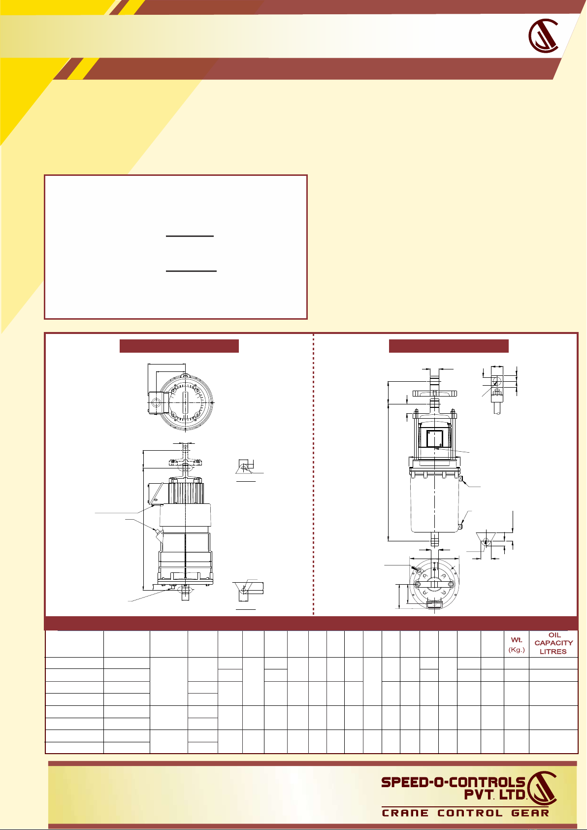
DIMENSIONS :
DIMENSIONS :
MSHOE
WIDTH
K LJ
7013
7013
130 100
130 100
385
435
433
385
445
108
88
18160
160 125
120 635
580
HhGEA B
350100 125
406100 125
160
235
265
110
145
160
350 146
148
Break Model
MDT - 150 - 15
MDT - 100 - 15
MDT - 160 - 15
563
508170
225
200
320
360
480
450
240
215
MDT - 250 - 18
MDT - 200 - 18
MDT - 150 - 18
MDT - 100 - 18
MDT - 160 - 18
14020205 145 780548250 275480525 270
MDT - 300 - 18
14
360
170
Thruster Brake MDT
( Drum Diameter100 to 250 mm. )
TECHNICAL DATA :
TECHNICAL DATA :
B
QN PC
Mass kg.
(S)
Thruster DetailsBrake Torque
(N)
N-m kg-m Model
Dia. mm
Force
Force
kg.
Brake Model
rake Drum
Stroke
50
150
5
100
606100
150
757.5
MDT - 100 - 15
MDT - 150 - 15
MDT - 100 - 18
MDT - 150 - 18
MDT - 160 - 15
350
200
250 35
20200MDT - 200 - 18
MDT - 250 - 18
90
MDT - 160 - 18 9
160
160
420300 42
MDT - 300 - 18
85
85
280135
349
51
160 110
10515015
ST 515
18018ST 520
14
17
11
12
22
18
30
QP
80
124
124
112
180
180
30
132
95
70
Mass kg.
C
Thruster Details
215
215
174
51
76
76
46
68
68
ST 545
ST 870
ST 870
460
680
680
kg.
Model
Force
(S)
(N)
Force
Stroke
444
508
508
N
190
68
114
ST 870
ST 8110
680
1140
ST 8110 114 1140
Brake Model
42
62
250
300
170
290
190500
400
500
MDT - 250 - 34 - 46
MDT - 400 - 68
MDT - 300 - 34 - 46
MDT - 500 - 68
MDT - 500 - 46
kg-m
Dia. mm
Brake Drum
350
580
600
600MDT - 600 - 114
MDT - 600 - 68
485MDT - 500 - 114 500
Brake Torque
1900
3500
5800
2900
4850
420
1700
620
N-m
27
11044451 174 112
34034
320
32200
ST 535
MDT - 200 - 34 - 46
85
90400MDT - 400 - 34 900
MDT - 400 - 46 110 1100 ST 545 46 460
400
132
ML SHOE
WIDTH
955
640
780
20
18
1130
25
180
108
140
J KHhGF
650
563
600
236
160
205
857 302
310
225
275
65
-
100
377
170
250
150 380 215
180
120
145
1300 240
970 322
475
150 485 235
EA B
Break Model
508
320
480
641
523
542
350
250
285
680800 410
MDT - 250 - 34 - 46
MDT - 300 - 34 - 46
MDT - 400 - 68
MDT - 500 - 68
MDT - 500 - 46
765688 215
MDT - 600 - 114
MDT - 600 - 68
MDT - 500 - 114
88
600540 160 125200180350463 215MDT - 200 - 34 - 46
MDT - 400 - 34
417 200
-
MDT - 400 - 46
682
Visit us at :
www.speedocontrols.com
www.socremote.com
H. O. Unit -I : C-15/16, Nand Jyot
Industrial Estate, Andheri-Kurla
Road, Mumbai - 400072 ,
Tel : (022) 42469700/730
E-mail : [email protected]
Unit - II: Plot No. 4912, G. I. D. C.,
Phase IV, Vatva,
Ahmedabad - 382445
Tel.
:
(079) 68169700/702/712
MILL DUTY THRUSTER BRAKES
Rated supply : 400/440 V / 50 Hz / 3 - Phase.
( Thrusters or other voltages ( up to 600 V ) on request.)
Thrusters should be mounted with in ± 10° from vertical.
Working fluid - Transformer oil to BS 148.
ELECTRO HYDRAULIC THRUSTER - (ST)
*
THRUSTER ST-515 / ST 518 / ST 520
1/8” BSP
OIL LEVEL PLUG
3/4" BSP CONDUIT
1/8" BSP
DRAIN
B
H
1/4" BSP.
ØC
PQ
M
SELECTION OF BRAKE SIZE
Electo-hydraulic thruster is a device which develops
linear thrust (or force) required to operate the required
mechanism. The input to the device is three phase
supply.
Where Hp/Kw = motor output & rpm = Rev/minute
T = Torque in Kgm = 716 x Hp
rpm
Kw
T = Torque in Nm
rpm
The brake torque must be than motor full
load as referred with drum. Formula as below:
=
>
=
Electro-hydraulic thruster is a device which develops
linear thrust (or force) required to operate the
required mechanism. The input to the device is
three phase supply. The thrusters are widely used
to actuate Thruster Shoe Brakes, commonly used
in material handling machines. Thrusters in various
models develop 15 kg to 295 kg. In stroke lengths of
51, 76 and 127 mm.
THRUSTER ST-535 . . . ST-13300
9552 x
TYPE THRUST
kgs.(N) STROKE
MM. WATTS ABCDE F GH J KLM P Q
VIEW ‘A’
2
3
6
12
34
ST 515
ST 520
ST 535
ST 545
ST 870
ST 8110
ST 13200
ST 13300
15 (150)
18 (180)
34 (340)
45 (450)
68 (680)
114 (1140)
225 (2250)
295 (2950)
51
76
127
90
150
180
200
250
420
580
280
349
444
508
660
51
76
127 254
215
174
160
130 19 25 13 12.7 19 16 19 30
32 19 110
105 85 62
25
32
38
54
48
41
22 30
85
95
15 19.7 21 27
25 32 16 22.2 40 24 29
25.4 30 27
19
38
32 45 152 132 55 9.0
5
110 85
110
P
Q
D
B
A
H
M
VIEW ’B’
ØC
JK
L
ØG
E
F
ØG
VIEW ‘A’
VIEW ’B’
A
DE
F
F
ØG
K
J
L
ØG
DRAIN PLUG
1/8” BSP
OIL FILLER
PLUG 1/4” BSP
TAPPED HOLE
3/4” BS CONDUIT
Visit us at :
www.speedocontrols.com
www.socremote.com
H. O. Unit -I : C-15/16, Nand Jyot
Industrial Estate, Andheri-Kurla
Road, Mumbai - 400072 ,
Tel : (022) 42469700/730
E-mail : [email protected]
Unit - II: Plot No. 4912, G. I. D. C.,
Phase IV, Vatva,
Ahmedabad - 382445
Tel.
:
(079) 68169700/702/712
This manual suits for next models
7


