BRP Evinrude E-TEC Series User manual

Main Menu


Printed in the United States.
© 2010 BRP US Inc. All rights reserved.
TM, ® Trademarks and registered trademarks of Bombardier Recreational Products Inc. or its affiliates.
BRP US Inc.
Technical Publications
250 Sea Horse Drive
Waukegan, Illinois 60085 United States
† AMP, Superseal 1.5, Super Seal, Power Timer, and Pro-Crimper II
are registered trademarks of Tyco International, Ltd.
† Amphenol is a registered trademark of The Amphenol Corporation.
† BEP is a registered trademark of Actuant Corporation.
† Champion is a registered trademark of Federal-Mogul Corporation.
† Deutsch is a registered trademark of The Deutsch Company.
† Dexron is a registered trademark of The General Motors Corporation.
† Fluke is a registered trademark of The Fluke Corporation
† GE is a registered trademark of The General Electric Company.
† GM is a registered trademark of The General Motors Corporation.
† Locquic and Loctite are registered trademarks of The Henkel Group.
† Lubriplate is a registered trademark of Fiske Brothers Refining Company.
† NMEA is a registered trademark of the National Marine Electronics Association.
† Oetiker is a registered trademark of Hans Oetiker AG Maschinen.
† Packard is a registered trademark of Delphi Automotive Systems.
† Permatex is a registered trademark of Permatex.
† STP is a registered trademark of STP Products Company.
† Snap-on is a registered trademark of Snap-on Technologies, Inc.
The following trademarks are the property of BRP US Inc. or its affiliates:
Evinrude ® Twist Grip™
Johnson ® Nut Lock™
Evinrude ® E-TEC ® Screw Lock™
FasTrak™ Ultra Lock™
S.A.F.E.™ Moly Lube™
SystemCheck™ Triple-Guard ® Grease
I-Command™ DPL™ Lubricant
Evinrude ® ICON™ 2+4 ® Fuel Conditioner
Evinrude ® / Johnson ® XD30™ Outboard Oil Carbon Guard™
Evinrude ® / Johnson ® XD50™ Outboard Oil HPF XR™ Gearcase Lubricant
Evinrude ® / Johnson ® XD100™ Outboard Oil HPF PRO™ Gearcase Lubricant
Gel-Seal II™

2
SERVICE MANUAL
CONTENTS
SECTION. . . . . . . . . . . . . . . . . . . . . . . . . . . . . . . . . . . . . PAGE
1 REFERENCE INFORMATION . . . . . . . . . . . . . . . . . . . . . 3
2 ROUTINE SERVICE . . . . . . . . . . . . . . . . . . . . . . . . . . . . 13
3 ENGINE COVER SERVICE . . . . . . . . . . . . . . . . . . . . . . 43
4 ENGINE MANAGEMENT MODULE (EMM) . . . . . . . . . . 49
5 SYSTEM ANALYSIS . . . . . . . . . . . . . . . . . . . . . . . . . . . . 67
6 ELECTRICAL AND IGNITION . . . . . . . . . . . . . . . . . . . . . 81
7 FUEL SYSTEM . . . . . . . . . . . . . . . . . . . . . . . . . . . . . . . 115
8 OILING SYSTEM . . . . . . . . . . . . . . . . . . . . . . . . . . . . . 141
9 COOLING SYSTEM . . . . . . . . . . . . . . . . . . . . . . . . . . . 157
10 POWERHEAD . . . . . . . . . . . . . . . . . . . . . . . . . . . . . . . . 167
11 MIDSECTION . . . . . . . . . . . . . . . . . . . . . . . . . . . . . . . . 197
12 GEARCASE . . . . . . . . . . . . . . . . . . . . . . . . . . . . . . . . . 243
13 TRIM AND TILT . . . . . . . . . . . . . . . . . . . . . . . . . . . . . . . 267
14 MANUAL STARTER . . . . . . . . . . . . . . . . . . . . . . . . . . . 279
SAFETY . . . . . . . . . . . . . . . . . . . . . . . . . . . . . . . . . . . . . . .S–1
INDEX . . . . . . . . . . . . . . . . . . . . . . . . . . . . . . . . . . . . . . . . . .I–1
TROUBLE CHECK CHART . . . . . . . . . . . . . . . . . . . . . . . . T–1
DIAGRAMS
IMPORTANT: For complete outboard rigging and control installation information, refer to the Predeliv-
ery and Installation Guide included with the service manual set.
All special tools referenced in this manual can be found in the Special Tools Guide, P/N 5008526.

REFERENCE INFORMATION
3
1
REFERENCE INFORMATION
TABLE OF CONTENTS
SAFETY NOTICE . . . . . . . . . . . . . . . . . . . . . . . . . . . . . . . . . . . . . . . . . . . . . . . . . . . . . . . . . . . . . . . . . . . . .4
ABBREVIATIONS USED IN THIS MANUAL . . . . . . . . . . . . . . . . . . . . . . . . . . . . . . . . . . . . . . . . . . . . . . . .6
UNITS OF MEASUREMENT . . . . . . . . . . . . . . . . . . . . . . . . . . . . . . . . . . . . . . . . . . . . . . . . . . . . . . . . . . . .6
LIST OF ABBREVIATIONS . . . . . . . . . . . . . . . . . . . . . . . . . . . . . . . . . . . . . . . . . . . . . . . . . . . . . . . . . . . . .6
EMISSION-RELATED INSTALLATION INSTRUCTIONS . . . . . . . . . . . . . . . . . . . . . . . . . . . . . . . . . . . . . .7
MANUFACTURER’S RESPONSIBILITY . . . . . . . . . . . . . . . . . . . . . . . . . . . . . . . . . . . . . . . . . . . . . . . . . . . .7
DEALER’S RESPONSIBILITY . . . . . . . . . . . . . . . . . . . . . . . . . . . . . . . . . . . . . . . . . . . . . . . . . . . . . . . . . . .7
OWNER’S RESPONSIBILITY . . . . . . . . . . . . . . . . . . . . . . . . . . . . . . . . . . . . . . . . . . . . . . . . . . . . . . . . . . .7
EPA EMISSION REGULATIONS . . . . . . . . . . . . . . . . . . . . . . . . . . . . . . . . . . . . . . . . . . . . . . . . . . . . . . . . .7
MODEL DESIGNATION . . . . . . . . . . . . . . . . . . . . . . . . . . . . . . . . . . . . . . . . . . . . . . . . . . . . . . . . . . . . . . . .8
MODELS COVERED IN THIS MANUAL . . . . . . . . . . . . . . . . . . . . . . . . . . . . . . . . . . . . . . . . . . . . . . . . . . .9
SERVICE SPECIFICATIONS . . . . . . . . . . . . . . . . . . . . . . . . . . . . . . . . . . . . . . . . . . . . . . . . . . . . . . . . . . .10
STANDARD TORQUE SPECIFICATIONS . . . . . . . . . . . . . . . . . . . . . . . . . . . . . . . . . . . . . . . . . . . . . . . .12
PRODUCT REFERENCE AND ILLUSTRATIONS . . . . . . . . . . . . . . . . . . . . . . . . . . . . . . . . . . . . . . . . . . .12

SAFETY NOTICE
Before working on any part of the outboard, read the SAFETY section at the end of this manual.
This publication is written for qualified, factory-
trained technicians who are already familiar with
the use of Evinrude/Johnson Special Tools. The
included information is not a substitute for work
experience. It is an organized guide for reference,
repair, and/or maintenance.
The following symbols and/or signal words
may be used in this document:
Indicates an instruction which, if
not followed, could severely damage engine
components or other property.
These safety alert signal words mean:
ATTENTION!
BECOME ALERT!
YOUR SAFETY IS INVOLVED!
IMPORTANT: Identifies information that controls
correct assembly and operation of the product.
DO NOT perform any work until you have read
and understood these instructions completely.
Torque wrench tightening specifications must
strictly be adhered to.
Should removal of any locking fastener (lock tabs,
locknuts, or patch screws) be required, always
replace with a new one.
When replacement parts are required, use
Evinrude/Johnson Genuine Parts or parts with
equivalent characteristics, including type, strength
and material. Use of substandard parts could
result in injury or product malfunction.
Always wear EYE PROTECTION AND APPRO-
PRIATE GLOVES when using power tools.
Unless otherwise specified, engine must be OFF
when performing this work.
Always be aware of parts that can move, such as
flywheels, propellers, etc.
Some components may be HOT. Always wait for
engine to cool down before performing work.
If you use procedures or service tools that are not
recommended in this manual, YOU ALONE must
decide if your actions might injure people or dam-
age the outboard.
This document may be translated into other lan-
guages. In the event of any discrepancy, the
English version shall prevail.
DANGER
Indicates a hazardous situation which, if
not avoided, will result in death or serious
injury.
WARNING
Indicates a hazardous situation which, if
not avoided, could result in death or seri-
ous injury
CAUTION
Indicates a hazardous situation which, if
not avoided, could result in minor or mod-
erate personal injury.
NOTICE

1
DANGER
Contact with a rotating propeller is likely to result in serious injury or death. Assure the
engine and prop area is clear of people and objects before starting engine or operating boat.
Do not allow anyone near a propeller, even when the engine is off. Blades can be sharp and
the propeller can continue to turn even after the engine is off. Remove propeller before ser-
vicing and when running the outboard on a flushing device.
DO NOT run the engine indoors or without adequate ventilation or permit exhaust fumes to
accumulate in confined areas. Engine exhaust contains carbon monoxide which, if inhaled,
can cause serious brain damage or death.
WARNING
Wear safety glasses to avoid personal injury, and set compressed air to less than 25 psi (172
kPa).
The motor cover and flywheel cover are machinery guards. Use caution when conducting
tests on running outboards. DO NOT wear jewelry or loose clothing. Keep hair, hands, and
clothing away from rotating parts.
During service, the outboard may drop unexpectedly. Avoid personal injury; always support
the outboard’s weight with a suitable hoist or the tilt support bracket during service.
To prevent accidental starting while servicing, disconnect the battery cables at the battery.
Twist and remove all spark plug leads.
The electrical system presents a serious shock hazard. DO NOT handle primary or secondary
ignition components while outboard is running or flywheel is turning.
Gasoline is extremely flammable and highly explosive under certain conditions. Use caution
when working on any part of the fuel system.
Protect against hazardous fuel spray. Before starting any fuel system service, carefully
relieve fuel system pressure.
Do not smoke, or allow open flames or sparks, or use electrical devices such as cellular
phones in the vicinity of a fuel leak or while fueling.
Keep all electrical connections clean, tight, and insulated to prevent shorting or arcing and
causing an explosion.
Always work in a well ventilated area.
Replace any locking fastener (locknut or patch screw) if its locking feature becomes weak.
Definite resistance to tightening must be felt when reusing a locking fastener. If replacement
is indicated, use only authorized replacement or equivalent.

6
REFERENCE INFORMATION
ABBREVIATIONS USED IN THIS MANUAL
Units of Measurement List of Abbreviations
A Amperes
amp-hr Ampere hour
fl. oz. fluid ounce
ft. lbs. foot pounds
HP horsepower
in. inch
in. Hg inches of mercury
in. lbs. inch pounds
kPa kilopascals
ml milliliter
mm millimeter
N·m Newton meter
P/N part number
psi pounds per square inch
RPM revolutions per minute
°C degrees Celsius
°F degrees Fahrenheit
ms milliseconds
µs microseconds
Ohms
VVolts
VAC Volts Alternating Current
VDC Volts Direct Current
ABYC American Boat & Yacht Council
ATDC after top dead center
AT air temperature sensor
BPS barometric pressure sensor
BTDC before top dead center
CCA cold cranking amps
CFR Code of Federal Regulations
CPS crankshaft position sensor
EMM Engine Management Module
EPA Environmental Protection Agency
ICOMIA International Council of Marine
Industry Associations
ID Inside dimension
MCA marine cranking amps
MWS modular wiring system
NMEA National Marine Electronics Assoc.
ROM read only memory
S.A.F.E. speed adjusting failsafe electronics
SAC start assist circuit
SAE Society of Automotive Engineers
SYNC synchronization
TDC top dead center
TPS throttle position sensor
USCG United States Coast Guard
WOT wide open throttle
WTS water temperature sensor

7
REFERENCE INFORMATION
EMISSION-RELATED INSTALLATION INSTRUCTIONS
1
EMISSION-RELATED
INSTALLATION
INSTRUCTIONS
Failing to follow these instructions when
installing a certified engine in a vessel violates
federal law (40 CFR 1068.105 (b)), subject to
fines or other penalties as described in the
Clean Air Act.
Maintenance, replacement, or repair of the emis-
sion control devices and systems may be per-
formed by any marine SI (spark ignition) engine
repair establishment or individual.
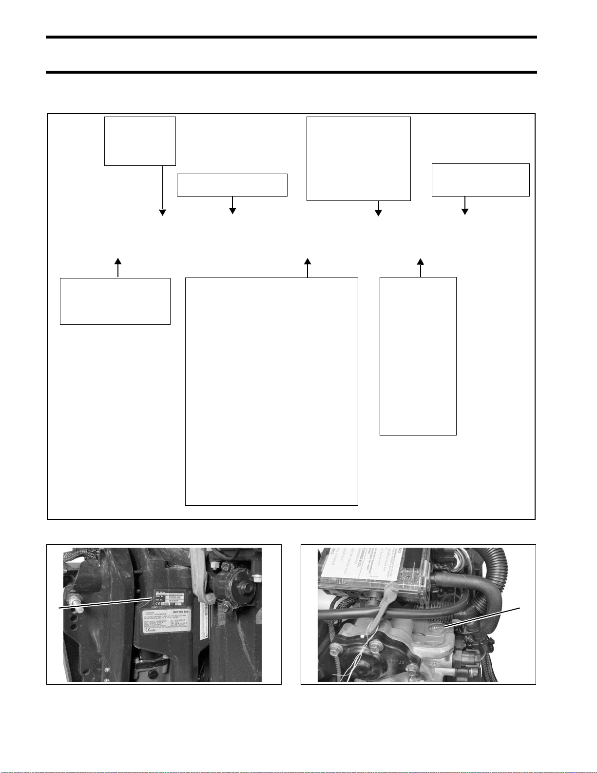
Manufacturer’s Responsibility
Beginning with 1999 model year outboards, man-
ufacturers of marine outboards must determine
the exhaust emission levels for each outboard
horsepower family and certify these outboards
with the United States of America Environmental
Protection Agency (EPA). An emissions control
information label, showing emission levels and
outboard specifications, must be placed on each
outboard at the time of manufacture.
Dealer’s Responsibility
When performing service on all 1999 and more
recent Evinrude/Johnson outboards that carry an
emissions control information label, adjustments
must be kept within published factory specifica-
tions.
Replacement or repair of any emission related
component must be executed in a manner that
maintains emission levels within the prescribed
certification standards.
Dealers are not to modify the outboard in any
manner that would alter the horsepower or allow
emission levels to exceed their predetermined
factory specifications.
Exceptions include manufacturer’s prescribed
changes, such as altitude adjustments, for exam-
ple.
Owner’s Responsibility
The owner/operator is required to have outboard
maintenance performed to maintain emission lev-
els within prescribed certification standards.
The owner/operator is not to, and should not allow
anyone to, modify the outboard in any manner
that would alter the horsepower or allow emis-
sions levels to exceed their predetermined factory
specifications.
Tampering with the fuel system to change horse-
power or modify emission levels beyond factory
settings or specifications will void the product war-
ranty.
EPA Emission Regulations
All new 1999 and more recent Evinrude/Johnson
outboards are certified to the EPA as conforming
to the requirements of the regulations for the con-
trol of air pollution from new watercraft marine
spark ignition outboards. This certification is con-
tingent on certain adjustments being set to factory
standards. For this reason, the factory procedure
for servicing the product must be strictly followed
and, whenever practical, returned to the original
intent of the design. The responsibilities listed
above are general and in no way a complete list-
ing of the rules and regulations pertaining to the
EPA requirements on exhaust emissions for
marine products. For more detailed information on
this subject, you may contact the following loca-
tions:
VIA U.S. POSTAL SERVICE:
Office of Mobile Sources
Engine Programs and Compliance Division
Engine Compliance Programs Group (6403J)
401 M St. NW
Washington, DC 20460
VIA EXPRESS or COURIER MAIL:
Office of Mobile Sources
Engine Programs and Compliance Division
Engine Compliance Programs Group (6403J)
501 3rd St. NW
Washington, DC 20001
EPA INTERNET WEB SITE:
www.epa.gov

8
REFERENCE INFORMATION
MODEL DESIGNATION
MODEL DESIGNATION
Model and serial numbers are located on the swivel bracket and on the powerhead.
BE 200 DP X II E
STYLE:
J = Johnson
E = Evinrude
HORSEPOWER
LENGTH:
= 15” Std.
L = 20” Long
Y = 22.5” Special
X = 25” X-long
Z = 30” XX-long
MODEL YR:
I=1
N=2
T=3
R=4
O=5
D=6
U=7
C=8
E=9
S=0
Ex: II = 2011
MODEL RUN
or SUFFIX
DESIGN FEATURES:
B = Blue Paint
C = Counter Rotation
D = Evinrude E-TEC®
E = Electric Start w/Remote Steering
F = Direct-Injection
G = Graphite Paint
H = High Output
J = Jet Drive
M = Military
P = Power Trim and Tilt
R = Rope Start w/Tiller Steering
S = Saltwater Approved
T = Tiller Steering
TE = Tiller Electric
V = White Paint
W = Commercial Model
PREFIX:
B = Bodensee model
D = ICON model
1. Model and serial number 007445
1
1. Serial number 007446
1

REFERENCE INFORMATION
MODELS COVERED IN THIS MANUAL
9
1
MODELS COVERED IN THIS MANUAL
This manual covers service information on all 35.1 cubic inch (.57 L), 2-Cylinder Evinrude E-TEC mod-
els.
Mode
l
Dis
p
lacement Gearcase Hei
g
ht Color Description
E15DHPLII_ .57 L,35.1 ci 13:28 /0.46 H 20" Blue Power Tilt,Remote Steering,ElectricStar
t
E15HPSLII_ .57 L,35.1 ci 13:28 /0.46 H 20" White Power Tilt,Remote Steering,ElectricStar
t
E15DHTLII_ .57 L, 35.1 ci 13:28 /0.46 H 20" Blue Power Tilt,Tiller Steering,Electric Start, Touch Troll
E15HTSLII_ .57 L,35.1 ci 13:28 /0.46 H 20" White Power Tilt,Tiller Steering,Electric Start, Touch Troll
E15HPSXII_ .57 L,35.1 ci 13:28 / 0.46 H 25" White Power Tilt, Remote Steering,Electric Star
t
E15HTSXII_ .57 L,35.1 ci 13:28 /0.46 H 25" White Power Tilt,Tiller Steering,Electric Start,Touch Troll
E25DRII_ .57 L,35.1 ci 13:28 /0.46 H 15" Blue Manual Tilt,Tiller Steering,Rope Start,Touch Troll
E25DRSII_ .57 L,35.1 ci 13:28 /0.46 H 15" White Manual Tilt,Tiller Steering,Rope Start,Touch Troll
E25DTEII_ .57 L, 35.1 ci 13:28 / 0.46 H 15" Blue Manual Tilt,Tiller Steering,ElectricStart,Touch Troll
E25DRLII_ .57 L,35.1 ci 13:28 /0.46 H 20" Blue Manual Tilt,Tiller Steering, Rope Start, Touch Troll
E25DRSLII_ .57 L, 35.1 ci 13:28 / 0.46 H 20" White Manual Tilt,Tiller Steering,Rope Start,Touch Troll
E25DTELII_ .57 L,35.1 ci 13:28 /0.46 H 20" Blue Manual Tilt,Tiller Steering,ElectricStart,Touch Troll
E25TESLII_ .57 L, 35.1 ci 13:28 /0.46 H 20" White Manual Tilt,Tiller Steering,ElectricStart, Touch Troll
E25DELII_ .57 L, 35.1 ci 13:28 /0.46 H 20" Blue Manual Tilt,Remote Steering,Electric Star
t
E25DPLII_ .57 L, 35.1 ci 13:28 /0.46 H 20" Blue Power Tilt, Remote Steering,Electric Star
t
E25DPSLII_ .57 L,35.1 ci 13:28 /0.46 H 20" White Power Tilt,Remote Steering,ElectricStar
t
E25DTLII_ .57 L, 35.1 ci 13:28 /0.46 H 20" Blue Power Tilt, Tiller Steering,Electric Start,Touch Troll
E25DTSLII_ .57 L,35.1 ci 13:28 /0.46 H 20" White PowerTilt,Tiller Steering,Electric Start,Touch Troll
E30DRII_ .57 L,35.1 ci 13:28 /0.46 H 15" Blue Manual Tilt,Tiller Steering,Rope Start,Touch Troll
E30DRSII_ .57 L,35.1 ci 13:28 /0.46 H 15" White Manual Tilt,Tiller Steering,Rope Start,Touch Troll
E30DPLII_ .57 L, 35.1 ci 13:28 /0.46 H 20" Blue Power Tilt, Remote Steering,Electric Star
t
E30DPSLII_ .57 L,35.1 ci 13:28 /0.46 H 20" White Power Tilt,Remote Steering,ElectricStar
t
E30DELII_ .57 L, 35.1 ci 13:28 /0.46 H 20" Blue Manual Tilt,Remote Steering,Electric Star
t
E30DRLII_ .57 L,35.1 ci 13:28 /0.46 H 20" Blue Manual Tilt,Tiller Steering, Rope Start, Touch Troll
E30DRSLII_ .57 L, 35.1 ci 13:28 / 0.46 H 20" White Manual Tilt,Tiller Steering,Rope Start,Touch Troll
E30DTLII_ .57 L, 35.1 ci 13:28 /0.46 H 20" Blue Power Tilt, Tiller Steering,Electric Start,Touch Troll
E30DTSLII_ .57 L,35.1 ci 13:28 /0.46 H 20" White PowerTilt,Tiller Steering,Electric Start,Touch Troll
E30DTELII_ .57 L,35.1 ci 13:28 /0.46 H 20" Blue Manual Tilt,Tiller Steering,ElectricStart,Touch Troll
E30TESLII_ .57 L, 35.1 ci 13:28 /0.46 H 20" White Manual Tilt,Tiller Steering,ElectricStart, Touch Troll

10
REFERENCE INFORMATION
SERVICE SPECIFICATIONS
15 HO Models 25 – 30 HP Models
ENGINE
Full Throttle
Operating Range RPM 15 HP – 5500 to 6100 RPM 25 HP – 5500 to 6100 RPM
30 HP – 5500 to 6100 RPM
Power 15 HP (11.2 kw) @ 5800 RPM 25 HP (30 kw) @ 5800 RPM
30 HP (37 kw) @ 5800 RPM
Idle RPM in Gear 750 ± 50 EMM Controlled
Idle RPM in Neutral 700 ± 50 EMM Controlled
Weight
(may vary depending
on model)
(DHPL) Models: 181 lbs. (82 Kg)
(DHTL) Models: 187 lbs. (85 Kg)
(R) Models: 152 lbs. (69 kg)
(RL) Models: 156 lbs. (71 kg)
(TE) Models: 166 lbs. (105 kg)
(TEL) Models: 170 lbs. (75 kg)
(DTL) Models: 191 lbs. (86 kg)
(DEL) Models: 164 lbs. (74 kg)
(PL) Models: 185 lbs. (84 kg)
Lubrication Evinrude/Johnson XD100, XD50, XD30; or
NMMA TC-W3 certified
Engine Type In-line, 2 Cylinder, Two-Cycle
Displacement 35.1 cu. in. (575 cc)
Bore 2.992 in (76 mm)
Stroke 2.500 in. (63.50 mm)
Standard Bore 2.9916 to 2.9931 in. (75.989 to 76.026 mm)
To bore oversize, add piston oversize dimension to standard bore
Top Crankshaft Journal 1.6235 to 1.6245 in. (41.237 to 41.262 mm)
Center Crankshaft Journal 1.7461 to 1.7470 in. (44.350 to 44.375 mm)
Bottom Crankshaft Journal 2.0450 to 2.0459 in. (51.942 to 51.967 mm)
Rod Crankpin 1.1815 to 1.1817 in. (30.011 to 30.016 mm)
Piston Ring End Gap, Both 0.011 to 0.019 in. (0.30 to 0.50 mm)
FUEL
Fuel/Oil Control EMM Controlled
Starting Enrichment EMM Controlled
Minimum (High) Fuel Pressure 28 to 32 psi (193 to 220 kPa)
Minimum Fuel Lift
Pump Pressure 2 psi (14 kPa)
Maximum Fuel Inlet Vacuum 4 in. Hg.
Minimum Octane 87 AKI (R+M)/2 or 90 RON
Additives 2+4 ®Fuel Conditioner, Fuel System Cleaner
Use of other additives may result in engine damage.
See FUEL SYSTEM REQUIREMENTS on p. 120 for additional information

REFERENCE INFORMATION
SERVICE SPECIFICATIONS
11
1
15 HO Models 25 – 30 HP Models
ELECTRICAL
Minimum Battery
Requirements 640 CCA (800 MCA) or 800 CCA (1000 MCA) below 32° F (0° C)
Alternator 15-Amp fully regulated Refer to Predelivery and Installation Guide for multiple battery
applications.
Tachometer Setting 6 pulse (12 pole)
Engine Fuse P/N 967545 – 10 A
COOLING
Thermostat 143°F (62°C)
Maximum Temperature 212°F (100°C)
IGNITION
Type IDI Inductive Ignition
Firing Order 1-2
Ignition Timing EMM Controlled
RPM Limit in Gear 6250
RPM Limit in Neutral 1100
Crankshaft Position Sensor Air
Gap Fixed
Spark Plug Refer to Emission Control Information Label
Champion†QC10WEP @ 0.028 ± 0.003 in. (0.71 mm)
GEARCASE
Gear Ratio 13:28 (.465)
Lubricant HPF XR Gearcase Lube
HPF Pro in high performance or commercial applications
Capacity 11 fl. oz. (325 ml)
Shift Rod Height fixed
Shift Cable Stroke 1.125 to 1.330 in. (28.6 to 33.8 mm) measured between NEUTRAL and FORWARD
POWER TRIM/TILT
Lubrication Evinrude/Johnson Biodegradable TNT Fluid
Fluid Capacity 11.7 fl. oz. (346 ml)
Trim Range 0° to 15°
Tilt Range 16° to 65°

12
REFERENCE INFORMATION
STANDARD TORQUE SPECIFICATIONS
STANDARD TORQUE
SPECIFICATIONS PRODUCT REFERENCE
AND ILLUSTRATIONS
BRP US Inc. reserves the right to make changes
at any time, without notice, in specifications and
models and also to discontinue models. The right
is also reserved to change any specifications or
parts, at any time, without incurring any obligation
to equip same on models manufactured prior to
date of such change. Specifications used are
based on the latest product information available
at the time of publication.
The continuing accuracy of this manual cannot be
guaranteed.
All photographs and illustrations used in this man-
ual may not depict actual models or equipment,
but are intended as representative views for refer-
ence only.
Certain features or systems discussed in this
manual might not be found on all models in all
marketing areas.
All service technicians must be familiar with nauti-
cal orientation. This manual often identifies parts
and procedures using these terms.
Size In. Lbs. Ft. Lbs. N·m
No. 6 7–10 0.58–0.83 0.8–1.1
No. 8 15–22 1.25–1.83 1.7–2.5
No. 10 24–36 2–3 2.7–4.0
No. 12 36–48 3–4 4.0–5.4
1/4 in. 60–84 5–7 7-9.5
5/16 in. 120–144 10–12 13.5–16.5
3/8 in. 216–240 18–20 24.5–27
7/16 in. 336–384 28–32 38–43.5
M3 15–22 1.25–1.83 1.7–2.5
M4 24–35 2–2.9 2.7–4.0
M5 35–60 2.9–5 4.0–6.8
M6 84–106 7–8.8 9.5–12
M8 177–204 14.7–17 20–23
M10 310–336 25.8–28 35–38
IMPORTANT: These values apply only when a
specific torque for a specific fastener is not listed
in the appropriate section. When tightening two
or more screws on the same part, DO NOT
tighten screws completely, one at a time.
WARNING
Torque wrench tightening specifications
must be strictly adhered to. Replace any
locking fastener (locknut or patch screw)
if its locking feature becomes weak. Defi-
nite resistance to turning must be felt
when reusing a locking fastener.
If replacement is specified or required
because the locking fastener has become
weak, use only authorized Evinrude/
Johnson Genuine Parts.
Nautical Orientation 006411

ROUTINE SERVICE
13
2
ROUTINE SERVICE
TABLE OF CONTENTS
INSPECTION AND MAINTENANCE SCHEDULE . . . . . . . . . . . . . . . . . . . . . . . . . . . . . . . . . . . . . . . . . . .14
LIFTING THE OUTBOARD . . . . . . . . . . . . . . . . . . . . . . . . . . . . . . . . . . . . . . . . . . . . . . . . . . . . . . . . . . . .15
OUTBOARD RIGGING CONNECTIONS . . . . . . . . . . . . . . . . . . . . . . . . . . . . . . . . . . . . . . . . . . . . . . . . . .17
CONTROL CABLE INSTALLATION . . . . . . . . . . . . . . . . . . . . . . . . . . . . . . . . . . . . . . . . . . . . . . . . . . . . . .18
SYSTEMCHECK HARNESS CONNECTIONS . . . . . . . . . . . . . . . . . . . . . . . . . . . . . . . . . . . . . . . . . . . . . . .20
BATTERY AND BATTERY CONNECTIONS . . . . . . . . . . . . . . . . . . . . . . . . . . . . . . . . . . . . . . . . . . . . . . .21
OETIKER CLAMP SERVICING . . . . . . . . . . . . . . . . . . . . . . . . . . . . . . . . . . . . . . . . . . . . . . . . . . . . . . . . .22
ADJUSTMENTS . . . . . . . . . . . . . . . . . . . . . . . . . . . . . . . . . . . . . . . . . . . . . . . . . . . . . . . . . . . . . . . . . . . . .24
STEERING FRICTION ADJUSTMENT . . . . . . . . . . . . . . . . . . . . . . . . . . . . . . . . . . . . . . . . . . . . . . . . . . . .24
THROTTLE FRICTION ADJUSTMENT . . . . . . . . . . . . . . . . . . . . . . . . . . . . . . . . . . . . . . . . . . . . . . . . . . . .24
TILLER HEIGHT ADJUSTMENT . . . . . . . . . . . . . . . . . . . . . . . . . . . . . . . . . . . . . . . . . . . . . . . . . . . . . . . .25
TILLER HANDLE RATCHET . . . . . . . . . . . . . . . . . . . . . . . . . . . . . . . . . . . . . . . . . . . . . . . . . . . . . . . . . . .25
TILLER HANDLE FRICTION . . . . . . . . . . . . . . . . . . . . . . . . . . . . . . . . . . . . . . . . . . . . . . . . . . . . . . . . . . .25
NEUTRAL SWITCH ADJUSTMENT . . . . . . . . . . . . . . . . . . . . . . . . . . . . . . . . . . . . . . . . . . . . . . . . . . . . . .25
TRIM SENDING UNIT ADJUSTMENT . . . . . . . . . . . . . . . . . . . . . . . . . . . . . . . . . . . . . . . . . . . . . . . . . . . .26
TRIM TAB ADJUSTMENT . . . . . . . . . . . . . . . . . . . . . . . . . . . . . . . . . . . . . . . . . . . . . . . . . . . . . . . . . . . .27
OPERATIONAL CHECKS . . . . . . . . . . . . . . . . . . . . . . . . . . . . . . . . . . . . . . . . . . . . . . . . . . . . . . . . . . . . .28
COOLING SYSTEM . . . . . . . . . . . . . . . . . . . . . . . . . . . . . . . . . . . . . . . . . . . . . . . . . . . . . . . . . . . . . . . . . .29
WATER INTAKE SCREENS . . . . . . . . . . . . . . . . . . . . . . . . . . . . . . . . . . . . . . . . . . . . . . . . . . . . . . . . . . .29
ENGINE FLUSHING . . . . . . . . . . . . . . . . . . . . . . . . . . . . . . . . . . . . . . . . . . . . . . . . . . . . . . . . . . . . . . . .30
RUNNING THE OUTBOARD USING A HOSE AND FLUSHING ADAPTER . . . . . . . . . . . . . . . . . . . . . . . . . . .31
LUBRICATION . . . . . . . . . . . . . . . . . . . . . . . . . . . . . . . . . . . . . . . . . . . . . . . . . . . . . . . . . . . . . . . . . . . . . .32
STEERING SYSTEM . . . . . . . . . . . . . . . . . . . . . . . . . . . . . . . . . . . . . . . . . . . . . . . . . . . . . . . . . . . . . . . .32
TILLER HANDLE . . . . . . . . . . . . . . . . . . . . . . . . . . . . . . . . . . . . . . . . . . . . . . . . . . . . . . . . . . . . . . . . . .32
SWIVEL BRACKET AND TRAILERING BRACKET . . . . . . . . . . . . . . . . . . . . . . . . . . . . . . . . . . . . . . . . . . .32
TILT TUBE . . . . . . . . . . . . . . . . . . . . . . . . . . . . . . . . . . . . . . . . . . . . . . . . . . . . . . . . . . . . . . . . . . . . . . .32
THROTTLE AND SHIFT LINKAGE . . . . . . . . . . . . . . . . . . . . . . . . . . . . . . . . . . . . . . . . . . . . . . . . . . . . . .33
PROPELLER SHAFT . . . . . . . . . . . . . . . . . . . . . . . . . . . . . . . . . . . . . . . . . . . . . . . . . . . . . . . . . . . . . . . .33
GEARCASE LUBRICANT . . . . . . . . . . . . . . . . . . . . . . . . . . . . . . . . . . . . . . . . . . . . . . . . . . . . . . . . . . . . .34
TRIM AND TILT . . . . . . . . . . . . . . . . . . . . . . . . . . . . . . . . . . . . . . . . . . . . . . . . . . . . . . . . . . . . . . . . . . .35
SPARK PLUGS . . . . . . . . . . . . . . . . . . . . . . . . . . . . . . . . . . . . . . . . . . . . . . . . . . . . . . . . . . . . . . . . . . . . .36
INDEXING . . . . . . . . . . . . . . . . . . . . . . . . . . . . . . . . . . . . . . . . . . . . . . . . . . . . . . . . . . . . . . . . . . . . . . .36
FUEL AND OIL SYSTEMS . . . . . . . . . . . . . . . . . . . . . . . . . . . . . . . . . . . . . . . . . . . . . . . . . . . . . . . . . . . . .37
FUEL FILTER . . . . . . . . . . . . . . . . . . . . . . . . . . . . . . . . . . . . . . . . . . . . . . . . . . . . . . . . . . . . . . . . . . . . .37
OIL FILTERS AND OIL RESERVOIR . . . . . . . . . . . . . . . . . . . . . . . . . . . . . . . . . . . . . . . . . . . . . . . . . . . . .37
AIR SILENCER . . . . . . . . . . . . . . . . . . . . . . . . . . . . . . . . . . . . . . . . . . . . . . . . . . . . . . . . . . . . . . . . . . . .37
HOSES AND CONNECTIONS . . . . . . . . . . . . . . . . . . . . . . . . . . . . . . . . . . . . . . . . . . . . . . . . . . . . . . . . . .37
ANTI-CORROSION PROTECTION . . . . . . . . . . . . . . . . . . . . . . . . . . . . . . . . . . . . . . . . . . . . . . . . . . . . . .38
STORAGE . . . . . . . . . . . . . . . . . . . . . . . . . . . . . . . . . . . . . . . . . . . . . . . . . . . . . . . . . . . . . . . . . . . . . . . . .39
FUEL SYSTEM TREATMENT . . . . . . . . . . . . . . . . . . . . . . . . . . . . . . . . . . . . . . . . . . . . . . . . . . . . . . . . . .39
INTERNAL ENGINE TREATMENT . . . . . . . . . . . . . . . . . . . . . . . . . . . . . . . . . . . . . . . . . . . . . . . . . . . . . . .39
ADDITIONAL RECOMMENDATIONS . . . . . . . . . . . . . . . . . . . . . . . . . . . . . . . . . . . . . . . . . . . . . . . . . . . . .40
PRE-SEASON SERVICE . . . . . . . . . . . . . . . . . . . . . . . . . . . . . . . . . . . . . . . . . . . . . . . . . . . . . . . . . . . . . .40
SUBMERGED ENGINES . . . . . . . . . . . . . . . . . . . . . . . . . . . . . . . . . . . . . . . . . . . . . . . . . . . . . . . . . . . . . .41

14
ROUTINE SERVICE
INSPECTION AND MAINTENANCE SCHEDULE
Routine inspection and maintenance is necessary to prolong outboard life. The following chart provides
guidelines for inspection and maintenance to be performed by an authorized Dealer.
IMPORTANT: Outboards used in rental, commercial, or other high hour applications require more fre-
quent inspections and maintenance. Adjust schedule for operating and environmental conditions.
Description
Engine
Care
Product Routine
Inspection
Every 300 hours
or every three
years (1)
(1) Average recreational use. Commercial use, heavy use, or use in salt or polluted water requires more frequent inspection and maintenance.
Emergency stop circuit and lanyard, check operation
Controls, steering and tilting; check operation
Engine mounting hardware, re-tighten
Fasteners, tighten any loosened components
Water intake screens, check condition
Cooling system; check water pump indicator
Anticorrosion anodes, check condition
Gearcase, check condition
Propeller, check condition
Fuel and oil systems, inspect and repair leaks (2)
(2) Emission-related component
Check battery connections and condition
Access EMM information, resolve any service codes
Electrical and ignition wires, inspect for wear or chafing
Fuel filter, replace
Gearcase lubricant, replace A
Spark plugs, inspect or replace (2)
Thermostats, inspect and check operation (2)
Grease fittings, lubricate (3)
(3) Annually in salt water applications
C
Power trim/tilt and fluid level, inspect B
Propeller shaft splines, inspect and lubricate (3) C
Starter pinion shaft, inspect and lubricate (3) D
Control cables, inspect and adjust
Steering cable, inspect and lubricate C
Water pump, inspect / replace (more often if water pressure loss or overheating occurs)
AHPF Pro Gearcase Lubricant
B Biodegradeable TNT Fluid (Single ram hydraulic systems)
CTriple-Guard Grease
D Starter Bendix Lube Only

15
ROUTINE SERVICE
LIFTING THE OUTBOARD
2
LIFTING THE
OUTBOARD
Remove shipping carton.
Use correct Lifting Fixture to lift outboard:
Install Lifting Tool, P/N 354717, on both sides of
the tilt tube.
Use an appropriate chain, at least 36 inches (91
mm) long with two snap hooks, each capable of
lifting 500 lbs. (227 kg).
Attach hooks to lifting device and attach chain to
hoist.
Lift the engine out of the carton.
Remove upper motor cover.
Place clean pad or cardboard on the floor.
WARNING
To avoid personal injury, make sure the lift-
ing capacity of the hoist is at least twice
the weight of the outboard.
DO NOT allow the lift hook or chain from
the hoist to come in contact with any part
of the engine during lifting.
Model Lifting Fixture
15–30 HP P/N 354717
1. Lifting tool, P/N 354717 007122
WARNING
To avoid personal injury or outboard dam-
age, be sure the lifting tool is fully threaded
on both sides of the tilt tube.
1
WARNING
Use this tool for horizontal lifting of 30 HP
and smaller Evinrude E-TEC models ONLY.
DO NOT use this tool to lift outboards
larger than 30 HP Evinrude E-TEC models.
To avoid personal injury and boat or out-
board damage, DO NOT use this tool to
install or remove outboard from transom
as outboard can unexpectedly tip.
1. Lifting tool, P/N 354717 007123
1

16
ROUTINE SERVICE
LIFTING THE OUTBOARD
Lower outboard onto the pad. Use hoist to care-
fully roll the outboard onto its port side.
Remove chain from lifting tool.
Remove lifting tool from outboard.
Attach chain to lift eye on back of engine block.
Carefully lift engine with hoist.
To avoid damage to the outboard,
lift the outboard in one smooth motion. DO
NOT allow the outboard to bounce.
CAUTION
To avoid damage to the outboard, DO NOT
allow the outboard to fall unrestrained.
007211
WARNING
If the chain snap hooks are too large, the
cast in lift eye could break causing the out-
board to drop suddenly causing personal
injury and damaging the outboard.
1. Lift eye 007212
007213
1
NOTICE

17
ROUTINE SERVICE
OUTBOARD RIGGING CONNECTIONS
2
OUTBOARD RIGGING
CONNECTIONS
IMPORTANT: For complete outboard rigging
and remote control installation information, refer to
the Predelivery and Installation Guide included
with the service manual set.
Common Practices – All Models
Control Cable Identification
IMPORTANT: Control cable function must be
identified before rigging outboard.
Identify each control cable:
•Put the control handle into NEUTRAL position.
The throttle cable casing guide will retract com-
pletely and the shift cable casing guide will go to
the midpoint of its travel.
Extend the control cables and lubricate them with
Triple-Guard grease.
Cable Retainer Clip Installation
When installing retainer clips on control arm link-
age pins, clips should be locked and must not be
bent or deformed.
For proper installation, review the following steps:
•Place washer on pin.
•Position retainer clip with straight section on the
bottom and angled section on the top.
•Use long nose pliers to insert straight section of
clip into linkage pin hole.
•Push the clip towards the hole while lifting on
the curved end with the pliers.
•Be sure retainer clip fully engages the pin.
•Lock the retainer by moving the angled section
behind the straight section.
1. Shift cable casing guide extended to midpoint
2. Throttle cable casing guide retracted DP0811
30501
1
2
1. Straight section
2. Angled section DP0818
DSC_4670
Locked Retainer Clip
1. Angled section behind straight section DP0817a
1
2
1

18
ROUTINE SERVICE
OUTBOARD RIGGING CONNECTIONS
Cable, Hose, and Wire Routing
Refer to Control Cable Identification on p. 17.
Remove cable entry grommet cover and grommet.
Remove rubber membrane from grommet holes
as needed.
Install cables and wiring harness(es) through
grommet as shown:
When grommet is in place and all cables have
been installed, tighten a tie strap around the out-
side of the grommet to form a watertight seal
around the cables.
Place blank sealing decal on lip of lower motor
cover at each harness connector tie strap to pre-
vent water intrusion.
After installation, make sure there
is enough clearance for all cables to avoid
binding or chafing through all engine steering
and tilting angles.
Control Cable Installation
Refer to Control Cable Identification on p. 17.
Make sure the remote control is in NEUTRAL, and
throttle is in the IDLE position.
Removal of lower motor covers is NOT required.
Some images show lower covers removed for
clear illustration.
Place the shift cable on the shift lever pin.
Hold the shift linkage in NEUTRAL.
Push and pull on the shift cable and observe the
cable slack. Hold the casing guide in the center of
the slack.
CAUTION
To prevent accidental starting while servic-
ing, disconnect the battery cables at the
battery. Twist and remove all spark plug
leads.
1. Cable entry grommet cover 007120
1. Throttle cable
2. Shift cable
3. Tiller wiring harness
007129
1
1
2
3
1. Tie strap
1. Blank sealing decal 007127
1
2
NOTICE
Other manuals for Evinrude E-TEC Series
2
This manual suits for next models
29
Table of contents
Other BRP Outboard Motor manuals

BRP
BRP Evinrude E-TEC Series User manual

BRP
BRP Evinrude E-TEC G2 Manual

BRP
BRP Johnson 4HP User manual

BRP
BRP Evinrude E-TEC G2 User manual

BRP
BRP Evinrude User manual

BRP
BRP Evinrude E-TEC 40 Manual

BRP
BRP Evinrude E15D Manual

BRP
BRP Johnson J30TEL4SUA 2007 User manual

BRP
BRP Evinrude E-TEC Manual

BRP
BRP 2995 Johnson User manual