Speedsignal RunLock B-339VO03 User manual

Installation Guide
RunLock
Volvo XC 60
Volvo XC 90
Volvo V 90
Volvo S 90
Vehicles manufactured in 2017 and onwards without TPMS
sensors in the tires
Art. No. B-339VO03
10R-058209
Carl-von-Ossietzky-Straße 3 Fax: +49 8061 49518 – 10 Homepage: www.speedsignal.de
D- 83043 Bad Aibling facebook: facebook.com/speedsignal

B-339VO03 Revision 3 2
Dear customer,
Thank you for your confidence in our products! This installation guide was created with utmost care and
is regularly revised. We cannot guarantee that this document is complete and free of errors or mistakes.
If you find any errors or have any difficulties, please let us know.
Thanks a lot! Your speedsignal support team
Contents
Contents .......................................................................................................................................................................... 2
Safety Instructions ........................................................................................................................................................... 2
Descriptions ..................................................................................................................................................................... 2
Scope of Delivery: Tools Required: .............................................................................................................................. 2
Installation Guide: ........................................................................................................................................................... 3
Installation Button ........................................................................................................................................................... 3
Tap Points ........................................................................................................................................................................ 4
Firewall CAN Modul ......................................................................................................................................................... 4
Connection Diagram ........................................................................................................................................................ 5
Functionality Test ............................................................................................................................................................ 7
Warranty Conditions: ...................................................................................................................................................... 7
Service: ............................................................................................................................................................................ 8
Safety Instructions
The installation of this product should only be carried out by trained specialist personnel and in accordance with
this manual.
speedsignal GmbH cannot accept any liability for injury to persons or damage to property from errors or mistakes
in this operating manual.
Please disconnect the battery before you start with the installation. During montage all additional supply lines
must be secured pursuant to their cross section and cable length. (DIN VDE 0298-4)
Descriptions
RunLock is an electrical circuit for vehicles, which enables you to remove the ignition key without switching of the
engine. According to vehicle type and equipment you can even lock the doors without interrupting the engine run.
Primarily it is intended for the use within authority vehicles in exercise of their duties.
For the installation into other vehicles (not authority) we point out that an unnecessary engine run is forbidden by
law in many countries such as in Germany according to StVO §30.
Scope of Delivery: Tools Required:
Interface Cable Sets RunLock- Torx- Removal Tool Drill Soldering
Button Screwdriver Iron
3540501 C-3540501 6003131
TX 25 Ø 12mm

B-339VO03 Revision 3 3
Installation Guide:
Flap to the left of the steering wheel Control unit CEM
Open the indicated screws and remove Attached to the A-pillar
Open the indicated screws CAN tap on the OBD connector
OBD socket rear panel Connector FL - CEM Connector IP - CEM
Installation Button 6003131
The button can be installed on a free button, as recommended on page 4.
Ø 12mm
2
1
3
TX
25
4
5
6
7

B-339VO03 Revision 3 4
Tap Points
There are 2 CAN taps on the vehicle, described here with CAN1 high / low and CAN2 high / low. A tap is made on
the FL connector of the CEM and a tap on the OBD connector.
* When an OFM (Firewall Can module) is installed tap at OFM
Firewall CAN Modul
CAN High Pin2
CAN Low Pin 3
For newer vehicles with installed OFM (Firewall CAN module) – Please notice, that the CAN on the OBD
plug is not working
The OFM module is installed under the driver’s seat
Signals Plug
CEM
PIN
CEM
Cable Colour
CEM
Cable Colour
IF
PIN IF MicroFit
Plug IF
RunLock signal 1 IP 44 grey
grey 8 10 point
RunLock signal 2 IP 42 grey-yellow
grey-yellow 9 10 point
CAN1-High FL 20 violet-white
white-yellow 4 6 point
CAN1-Low FL 19 violet-green
white-brown 1 6 point
LIN FL 39 Dark green
geen-grey 5 6 point
CAN2-High OBD II* 6 white-green
blue-white 5 10 point
CAN2-Low OBD II* 14 green-yellow
white-brown 10 10 point
12 Volt any with 5A red
ground any brown
Front
view
OBD
B-339VO03 Revision 3 5
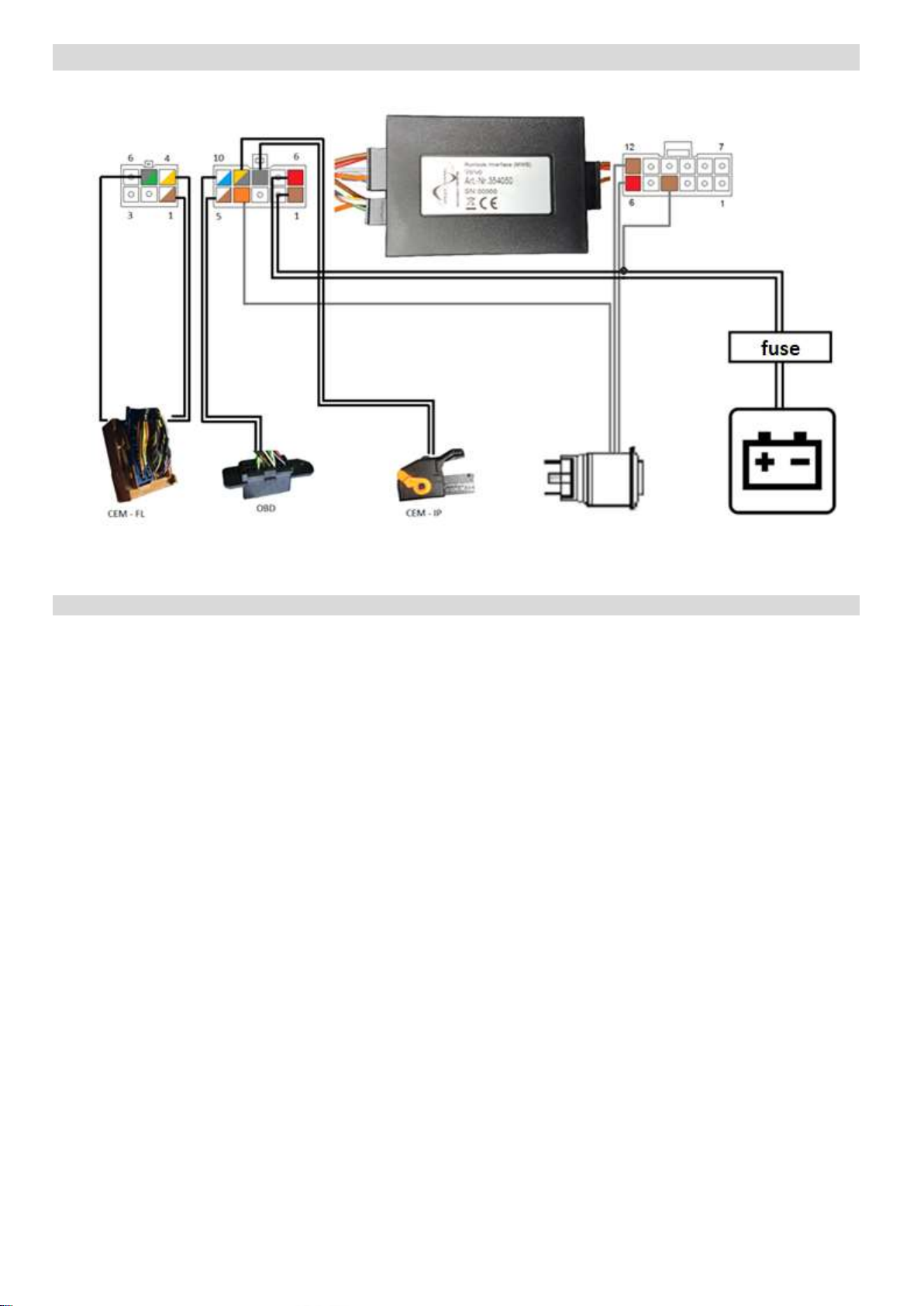
Connection Diagram
Plug FL at the CEM OBD socket Plug IP at the CEM RunLock button battery

B-339VO03 Revision 3 5
1) For those who use Runlock with a special signaling system activated.
Pin Assignment 6-pole minifit-plug
Input/Output Designation Cable Colour Remark
1 Input CAN1-Low white-brown
2 not assigned --- --- ---
3 not assigned --- --- ---
4 Input CAN1-High white-yellow
5 Input LIN green-grey
6 not assigned --- --- ---
Pin Assignment 10-pole minifit-plug
Input/Output Designation Cable Colour Remark
1 Input ground brown
2 not assigned --- --- ---
3 not assigned --- --- ---
4 Output illumination orange buttons
5 Input CAN2-Low* white * With OFM (firewall CAN module) see page 4
6 Input power supply 12V red
7 not assigned --- --- ---
8 Output RunLock signal 1 grey
9 Output RunLock signal 2 grey-yellow
10 Input CAN2-High* blue-white * With OFM (firewall CAN module) see page 4
Pin Assignment 12-pole minifit-plug
Input/Output Designation Cable Colour Remark
1 not assigned --- --- ---
2 not assigned --- --- ---
3 not assigned --- --- ---
4 Input SOSI brown if ground is connected -> RunLock can be acti-
vated 1)
5 not assigned --- --- ---
6 Input IN button red buttons
7 not assigned --- --- ---
8 not assigned --- --- ---
9 not assigned --- --- ---
10 not assigned --- --- ---
11 not assigned --- --- ---
12 Input ground brown buttons

B-339VO03 Revision 3 7
Functionality Test
For activating RunLock successfully, please follow these steps:
1. Start the engine
2. Pull the hand brake
3. Shift into neutral / automatic: switch to parking position
4. Remove your feet from the pedals
5. Button flashes
6. Press the RunLock button -> button is lit continuously
7. Vehicle can be locked with original key
To deactivate the motor override, please observe the following procedure:
1. Unlock the vehicle
2. Press the RunLock button
The engine will shut off if you touch the pedals before you deactivate the RunLock and/or insert key to ignition
switch to position II.
For security reasons the engine will always shut off after deactivating the RunLock on vehicles with keyless-go-
function.
Illumination and flashing behaviour of RunLock button:
button flashes: All conditions for activating the RunLock are fulfilled.
button illuminates constantly: RunLock is activated successfully
button does not illuminate: RunLock is deactivated successfully
Warranty Conditions:
speedsignal GmbH guarantees within the legal deadline of 2 years from the original date of purchase that this pro-
duct is free from defects in material and workmanship as long as this product was installed similar to our installa-
tion-on guide.
If repairs of processing errors or malfunctions of this product are necessary within the warranty period, speedsig-
nal will repair the product or replace it with a flawless product. To be able to assert the benefit of these provisions,
you need the proof of purchase.
Warranty claim and operating license lapses:
unauthorised changes on the device or accessory
self-initiated repairs at the device
improper use or operation
violent impacts to the device (fall down, wanton destruction, accident, etc.)
For installation please notice all safety and legal regulations.
When installing electronic assemblies into vehicles please note the installation guidelines and warranty conditions
of the vehicle manufacturer.
In any case you have to inform the principal (vehicle owner) about the installation of this interface and about all
risks.
It is therefore recommended to get in contact with the vehicle manufacturer or with an authorized workshop to
exclude any risks.

B-339VO03 Revision 3 8
Service:
Telephone support: +49 8061 49518 – 0
Monday to Friday 8:00 a.m. until 6:00 p.m.
Opening hours:
Monday to Friday 8:00 a.m. until 5:30 p.m.
MEZ (UTC +1h)
MESZ (UTC +2h)
Carl-von-Ossietzky-Straße 3 Fax: +49 8061 49518 – 10 Homepage: www.speedsignal.de
D- 83043 Bad Aibling facebook: facebook.com/speedsignal
Table of contents
Popular Car Alarm manuals by other brands

Drake Systems
Drake Systems DTH-3002R user manual

Clifford
Clifford 20.5X owner's guide

Audiovox
Audiovox Prestige APS-25KB installation manual

Audiovox
Audiovox Prestige AS-9256 installation manual

Directed Electronics
Directed Electronics PS-7870TWE-FM user guide

Code Alarm
Code Alarm CATX2LED Programming guide


Code Alarm
Code Alarm CA 310 owner's manual

CrimeStopper
CrimeStopper Gargoyle CS-2001FC II Series Installation & operating instructions

Clifford
Clifford Concept 100 owner's manual

Lexus
Lexus DTC B2795 Technical Service Information Bulletin

Omega
Omega Excalibur RS-X70 installation guide

Audiovox
Audiovox Prestige 128-8146 owner's manual