Speedway 350-400 User manual

1
350-400
INSTRUCTIONS
© 2019, Speedway Motors, Inc.
Unser Rear Suspension
62-67 Chevy Nova
350003.1
350003.2
350400.1
350021.1
350009
350029.2
65579031-25.5
65579031-30
350800.4
350029
350402
G-Comp Chassis Brace
G-Comp Front Support
Chevy II Unser Rear Arms (pair)
G-Comp Upper Crossmember
G-Comp 54” Floater Rear Housing
Floater Components
25.5” Double Splined Axle - 31
30” Double Splined Axle - 31
Hardware Kit - Unser Rear
G-Comp Rear Watts Link Package
G-Comp Rear Sway Bar - Nova
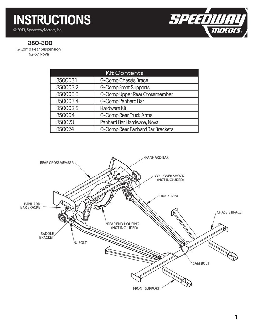
Kit Contents
G-COMP TRUCK ARMS - UNSER EDITION
CHASSIS BRACE
FRONT SUPPORT BRACES
ECCENTRIC CAMS
COIL OVERS (NOT INCLUDED)
REAR UPPER CROSSMEMBER
FORD NINE INCH FLOATER
REAR END HOUSING
WATTS LINK PIVOT
WATTS LINK RODS
U-BOLTS
FLOATER
HUBS
SWAY BAR ARMS

2
350-400
INSTRUCTIONS
© 2019, Speedway Motors, Inc.
Unser Rear Suspension
62-67 Chevy Nova
1. Remove Rear Suspension: Raise the car and support it with jack stands or a lift. Remove the exhaust,
drive shaft, rear end, and all rear suspension components including the rubber bump stops. Disconnect
fuel lines and remove fuel tank. Remove fuel lines, brake lines, and E-brake cables from bottom of car.
These can be re-routed through the holes in the chassis brace after installation.
2. Prep for Welding by raising the chassis brace into its approximate position and mark all areas that will
be welded. These areas should be ground down to bare metal to provide the proper conditions for
welding. (Any carpet or padding installed on back side of weld areas should be removed at this time.) To
position the chassis brace, the rear flanges of the chassis brace should be clamped tight against the leaf
spring boxes while the chassis brace is pushed up against the bottom of the car and centered left to right.
5/16-18 X 3/4" BOLTS
(THREAD INTO FACTORY SHOCK BOLT HOLES)
CLAMP THESE FLANGES TIGHT
AGAINST THE FRONTLEAF SPRING BOXES
TO LOCATE THE CROSSMEMBER.
SLIP OVER FACTORY FLOOR SUPPORTS
FRONT SUPPORT TUBES SHOULD FIT TIGHT
AGAINST CROSSMEMBER FOR WELDING
FIT BETWEEN ROCKERS
FIT BETWEEN FRAME RAILS
3. Repeat step two with the rear cross member and front supports. Depending on the car, minor
trimming/fitting may be required. Bolt the upper rear crossmember to the car using the four supplied
5/16”-18 x 3/4” bolts. These bolts will go into the factory shock bolt holes. This will locate the
crossmember in the proper location.

3
350-400
INSTRUCTIONS
© 2019, Speedway Motors, Inc.
Unser Rear Suspension
62-67 Chevy Nova
4. Tack-Weld Crossmembers: Once all areas that will be welded are prepped and cleaned, then the
cross member, chassis brace, and front supports can be tack welded into place. (Some grinding and
trimming may be necessary to provide proper fit up.) Note: Do not fully weld the crossmembers at
this time! Only weld enough to securely hold the parts in place during mock up. Hint: Weld in places
that can be easily accessed with a grinder in case it becomes necessary to move or adjust the parts.
5. Assemble Truck Arms and Rear End Housing: Install the truck arms onto the front cross member
using the supplied 3/4"-16 X 5-1/2” cam bolts and spacers. Note: Install the cam bolts in the center
of adjustment as shown. The flat side of the bolt should be facing upwards. Tighten the nut until it just
touches the cam spacer, but do not fully tighten it yet.
Raise the rear end housing into its approximate location.
Using the supplied U-bolts and nuts, attach the
truck arms to the rear end housing. The U-bolts
only need to be snug at this time. There is no
need to fully tighten them yet. With the rear
end housing connected to the truck arms,
and raised up to ride height, you can now
tighten the cam bolts.
6. Install the Watts Link Pivot: Once the truck arms have been connected to the rear end housing, it’s
time to mock up the watts link. Start by installing the center pivot to the rear end housing. Use the
supplied 3/4-16 x 3” bolt and washer to attach the pivot to the housing as shown. For initial mock up,
use the second hole from the top on the rear end housing.
3/4-16 X 3" BOLT
3/4" WASHER
5/8-18 X 5" BOLT
5/8-18 X 4 1/2" BOLT
5/8-18 THIN
LOCK NUT
5/8-18 THIN
LOCK NUT
(2X) 5/8-18 X 1 3/4"
BOLT
(2X) 5/8-18 THIN
LOCK NUT

4
350-400
INSTRUCTIONS
© 2019, Speedway Motors, Inc.
Unser Rear Suspension
62-67 Chevy Nova
7. Install the Link Rods: Start by assembling the link rods. Install the lower/drivers side link rod first. Install
one end of the link into the lower location on the pivot using the 5/8-18 x 1 3/4" bolt and lock nut.
Install the other end of the link to the chassis. Use the center hole location and a 5/8-18 x 4-1/2” bolt
and lock nut. Once the link is installed, adjust the length of the link by spinning the tube until the pivot is
at a 90° angle with the ground. Note: The link should be level with the ground at this time. The rear end
housing may need to be raised or lowered to achieve this. Once the link is level with the ground, and the
pivot is at a 90° angle, the jam nuts can be tightened. With the first link installed, it is now time to install
the upper/passenger side link. Start by using the 5/8-18 x 1 3/4" bolt and lock nut to connect one
end of the link to the center pivot. Now, hold the link up in its approximate position and adjust the link
until the outer rod end lines up with the center hole location on the chassis. Use the 5/8-18 x 5” bolt
and lock nut to connect the link to the chassis. Now you can tighten the jam nuts on this link. Be sure to
keep the rod ends adjusted evenly on either side of the tube. Note: The center pivot bolts must be installed
as shown, with the nut towards the rear of the car. Installing them in the other direction may result in
interference between the bolt and the rear end housing. With the links adjusted properly and the rear end
at ride height, both links should be parallel to the ground and the pivot should be at a 90° angle.
8. Check Alignment and Clearances: On most cars, a portion of the trunk floor will need to be raised to clear
the center pivot and upper link at full compression. The affected area is the passenger side trunk floor just
in front of the fuel tank (shown below). Note: It is a good idea to leave room to clear the pivot and link rod
even in the upper most position.
Cycle the suspension
completely though its
travel and check for
any clearance issues
with the truck, floor,
etc…
24"
4"
RAISED TRUNK FLOOR
TOP VIEW OF REAR CROSSMEMBER
TOWARDS FRONT OF CAR
9. Weld: If there are no clearance issues, it is time to fully weld in the crossmembers. Start by removing
the rear end, watts link, and truck arms from the car. Take note which link rod goes on which side. Fully
weld the cross member, chassis brace, and front supports to the car. Note: It is a good idea to only weld a
small bead at a time, then move to a new area and allow the first area to cool completely before welding
further in that area. This will greatly reduce the risk of warping.

5
350-400
INSTRUCTIONS
© 2019, Speedway Motors, Inc.
Unser Rear Suspension
62-67 Chevy Nova
10. Final-Assembly: Once all of the welding is complete, the suspension can be assembled.
11. Now is a good time to fully assemble the rear end by installing gears, hubs, axles, and brakes.
Note: This can also be done after installing the housing into the car. Assemble the hub as shown below.
Be sure to pack the wheel bearings with high quality grease. Do not over torque the axle nut! The hub
should spin freely with zero endplay. To achieve this, assemble the hub as shown. Tighten the axle nut
and spin the hub a dozen or so rotations. Now back
the axle nut off 2 full turns. Then tighten the
axle nut until it just starts to get snug. At
this point the hub should spin freely
with little to no resistance, and
there should be no
endplay in the
bearing. Bend
the tab on the
lock ring into the
groove on the axle nut. This
will prevent the axle
nut from loosening.
HUB
OUTER WHEEL BEARING RACE
OUTER WHEEL BEARING
AXLE NUT RETAINING RING
AXLE NUT
DRIVE FLANGE SEAL
DUST CAP SEAL
DRIVE FLANGE BOLTS (2X)
DUST CAP
DUST CAP BOLTS
INNER WHEEL BEARING RACE
INNER WHEEL BEARING
HUB SEAL
HUB SEAL RETAINING RING
INNER AXLE SEAL
AXLE TUBE
DRIVE FLANGE
12. Secure the truck arms to the chassis brace using the cam bolts and cam spacers as shown in step 5.
13. Raise the complete rear end into position. Attach the rear end to the truck arms using the supplied
u-bolts, washers, and nuts.
14. Install the Watts link center pivot as described in step 6.

6
350-400
INSTRUCTIONS
© 2019, Speedway Motors, Inc.
Unser Rear Suspension
62-67 Chevy Nova
15. Install the link rods back into their previous locations and tighten.
16. Install the sway bar as shown. Press the sway bar bushings into the sway bar housing on the
crossmember by lightly tapping them into place with a rubber mallet (be sure the bushings are going
in straight). With the bushings in place, slide the sway bar into the housing. Slide one of the torsion
arms onto the splined portion of the sway bar so it sits flush with the end of the bar. Install the
5/16-24 x 2” bolt and lock nut onto the arm and tighten. Install one of the male rod ends onto the
outside of the arm using a 3/8-16 x 1-1/4" bolt. Now thread the jam nut and female rod end onto the
male rod end leaving roughly 1/4” of threads showing. Attach the female rod end to the rearend
housing using 3/8-24 x 1-1/4" bolt and lock nut. Assemble the opposite side in the same manner. The
arms will need to be “clocked” about 45° relative to one another, with the passenger
side at a downward slope and the driver side at an upward slope. Note: Once
the vehicle is fully assembled and sitting on level ground, it is a good
idea to disconnect one side of the sway bar links
and adjust the length of the rod ends until
there is no pre-load and the holes line
up perfectly.
SWAY BAR HOUSING
SWAY BAR BUSHING
SWAY BAR
SWAY BAR ARM
5/16-24 LOCK NUT
MALE ROD END
3/8-16 X 1-1/4"
FEMALE ROD END
3/8-24 JAM NUT
5/16-24 X 2"
BOLT
3/8-24 X 1 1/4" BOLT
3/8-24 LOCK NUT
1 7. Install the brakes as per the instructions included with your brake kit. Note: For recommended part
numbers please visit our website or contact one of our tech experts.

7
350-400
INSTRUCTIONS
© 2019, Speedway Motors, Inc.
Unser Rear Suspension
62-67 Chevy Nova
1/2"-20 X 2-1/4"
BOLT
1/2"-20 LOCK NUT
1/2"-20 X 3"
BOLT
1/2"-20
LOCK NUT
(2X) 5/16" WIDE SPACER
(2X) 7/16"-20
LOCK NUT
(2X) 7/16"-20 X 1-1/4"
BOLTS
COIL-OVER SHOCK
(NOT INCLUDED)
SHOCK MOUNT
ON TRUCK ARM
18. Install the coil-over shocks. The
Unser Edition G-Comp rear
suspension features an adjustable
lower shock mount. To install the
shock, first use the two 7/16”-20 x 1 -1/4”
bolts and lock nuts to install the shock
brackets to the shock mount on the truck
arm. Then use a 1/2”-20 x 2-1/4” bolt and
lock nut to secure the lower end of the
shock to the truck arm as shown. The
remaining 1/2”-20 x 3” bolts and lock
nuts are used along with two 5/16” spacers
to install the top of the shocks into the
rear crossmember. Note: This kit is
designed to use 4” stroke shocks with
a compressed length of 10”-11” and an
extended length of 14”-15”. Shock ends
should be 1/2” bearings with a mounting
width of 1”. For recommended part numbers,
please visit our website or contact one of our
tech experts.
19. Re-install the drive shaft, fuel tank, fuel lines, brake lines, exhaust, etc... Bleed the brakes. Fill the rear
end with fluid. Install wheels and tires.
20. Alignment:
Lower the car onto the ground and check for desired ride height. Adjust ride height if necessary by raising
the car and spinning the adjusting collar on the coil-over. Once the ride height has been set, lower the car
onto the ground and make sure the rear end is centered in the car body. Adjust the watts link rods if
necessary. For optimum handling and performance, both rods should be parallel with the ground and
the center pivot should be at a 90° angle. This kit provides multiple mounting locations for the watts link
to allow for different ride heights. Now that the ride height is set and the rear end is centered perfectly in
the car, the rear end can be aligned by adjusting the cam bolts on the front of the truck arms. Note: This is
difficult to do accurately and a professional alignment is recommended. This method will get you close
enough to drive the car to an alignment shop.

SpeedwayMotors.com/Info/FAQ
DISCLAIMER In an effort to offer our customers low prices, quick service
and great value, Speedway Motors reserves the right to change suppliers,
specifications, colors, prices, materials without notice. Prices and policies that
were current and in effect at the time of printing are also subject to change
without notice. Quantities are limited on some items. Any unauthorized use of
this catalog including words, photos or drawings is prohibited. Speedway is not
responsible for any typographical errors, printing errors or misinterpretations
WARRANTY DISCLAIMER Purchasers understand and recognize that racing
parts, specialized street rod equipment, and all other parts and services sold
by Speedway Motors, Inc. are exposed to many and varied conditions due
to the manner in which they are installed and used. Except for certain limited
warranties, if any, set forth in Speedway Motors, Inc.’s current catalog with
respect to the products and/or parts thereof identified on your invoice, each
product,andeachpartthereof,issold“asis”,and“withallfaults”andSpeedway
Motors, Inc. makes no warranties either expressed or implied, writtenor
oral, with regard such products and services including, without limitation,
any warranty of merchantability or fitness for a particular purpose. Without
limiting the foregoing, there is no warranty expressed or implied as to whether
the goods sold hereby will protect purchasers or ultimate end-users of such
products and parts from injury or death. In no event shall Speedway Motors,
Inc. be liable for any special, incidental or consequential damages, or any other
damages whatsoever arising out of or connected with the use or misuse of the
products and each part thereof. Purchasers acknowledge and agree that no
person, entity or agent of Speedway Motors, Inc. has any authority to make
any statement contrary to this disclaimer and that any warranty statements
or representations allegedly made on behalf of Speedway Motors, Inc. by any
such person, entity or agent are void. Purchasers are relying solely on their own
skill and judgment to select, purchase and use suitable products and assume
all responsibility and risk with regard thereto. Some local laws prohibit the use
of utility jugs, funnels and barrel pumps for dispensing fuel. Please check your
own state for more information, regulations or further direction in your use of
the utility jugs, funnels and barrel pump described in Speedway’s catalogs or
on Speedway Motors websites. Some parts in this catalog are not legal for sale
or use in California. Items sold in this catalog are for racing vehicles which may
never be used on a highway. The use of manufacturer’s names and symbols
are for reference purposes only.
DAMAGE CLAIMSPlease inspect all packages upon delivery and in the
presence of the delivery driver when possible. The driver must note any visible
damage and provide procedures for handling damage claims. To allow for a
claims process, please retain original box, packing material and damaged
merchandise. Contact Speedway Motors for instructions regarding damage
claim within 5 days of receipt. Speedway Motors assumes no liability after
this period.
SHORTAGES Please check the contents of your delivery to ensure that all
parts ordered are received. Refer to your invoice to cross check all items
received and inspect all packing materials for contents of small items. Retain
original shipping box and packing materials. Orders may be split into multiple
boxes which can be delivered on different days. Contact Speedway Motors
for instructions regarding shortage claim within 5 days of receipt. Speedway
Motors assumes no liability after this 5 day period.
REFUSALS All refused packages will be billed the freight to and from the
destination and refused COD orders will be billed a 15% restocking charge plus
freight to and from destination.
WARRANTY CLAIMS If the item is used or installed and a warranty claim
request is submitted, warranty work is done by the manufacturer and may
take up to 30 days for processing. Speedway Motors will be required to
follow the manufacturer’s warranty instructions to allow for a credit refund or
exchange when specified.
RETURNS We want you to be satisfied with your purchase. If you are not
satisfied, you may return your new, unused item within 60 days for refund or
exchange.
All exchanged or returned merchandise must be in original factory condition
with no modifications or alterations. Returned merchandise must include
original packaging materials, warranty cards, manuals, instructions, etc. If the
returned item requires repackaging, your refund / exchange will be subject
to a repackaging charge.Return/Exchange transactions less than $99 are
excluded from the free shipping offer.
HOW TO RETURN AN ITEM Please re-pack the item in a sturdy box, include
a copy of your invoice and completed return form. Returns must be shipped
prepaid. CODs are not accepted. Shipping costs for exchanged merchandise
will be charged to your credit card.
Items that are returned after 60 days are subject to a 15% restocking charges.
Fiberglass items returned will be subject to a 15% restocking charge. We are
unable to accept returns on electrical parts, video tapes, DVD’s, books, special
order or closeout merchandise.
BRAKE INSTALLATION ALERT The selection and installation of brake
components should only be done by personnel experienced in the proper
installation and operation of braking systems. The installer must use his/
her own discretion to determine the suitability of all brake components
and brake kits for every particular application. Speedway Motors, Inc.
makes no warranties either expressed or implied including any warranty of
merchantability or fitness for a particular purpose, other than those contained
in its current catalog or website with respect to the goods identified on the
face of the invoice. There is no warranty expressed or implied as to whether
the goods sold hereby will protect the purchaser or ultimate user of such
goods from injury of death.
EXHAUST INSTALLATION ALERTExhaust systems and other component
surface finishes are not permanent. Coatings, paint and other factory supplied
cosmetic treatments are only intended to protect from surface corrosion in
an unused state. No returns are allowed after the parts have been installed.
Header flanges must be clean and clear of paint and surface contaminants
prior to mating to exhaust gaskets. Exhaust fasteners must be re-torqued
after the initial heat cycle and regularly thereafter to ensure a proper gasket
seal is maintained. Should you decide to install this exhaust product at your
home, be warned that pleasure car or light duty truck/van “bumper” jacks
are intended for emergency use only. The use of frame contact jack stands
in conjunction with a floor jack as a main support is highly recommended to
minimize accidental dropping of a vehicle while the installation proceeds. We
recommend the use of a shop hoist if possible. Please use caution! Speedway
Motors, Inc. makes no warranties either expressed or implied including any
warranty of merchantability or fitness for a particular purpose, other than
those contain in its current catalog or website with respect to the goods
identified on the face of the invoice. There is no warranty expressed or implied
as to whether the goods sold hereby will protect the purchaser or ultimate user
of such goods from injury or death.
CHECK LOCAL LAW Some parts are not legal for sale or use in California on
any pollution controlled motor vehicles. These items are legal in California for
racing vehicles only which may never be used upon a highway. Check local
law.
Speedway Motors, Inc.
P.O. Box 81906 • Lincoln, NE 68501
800.979.0122 • SpeedwayMotors.com
Find the above info on our website:
© 2019, Speedway Motors, Inc.
IMPORTANT
Other Speedway Automobile Accessories manuals
Popular Automobile Accessories manuals by other brands
TrailFX
TrailFX A1545S quick start guide

Safe Fleet
Safe Fleet Rear View Safety RVS-918718 instruction manual
Metra Electronics
Metra Electronics 99-8223 installation instructions
Safe Fleet
Safe Fleet Prime Design AR1413 manual

TAUBENREUTHER
TAUBENREUTHER 2351-02 manual
Jaeger
Jaeger 21010524 Fitting instructions

