Speedway G-Comp 350-500 User manual
1
350-500
70-81 Chevy Camaro
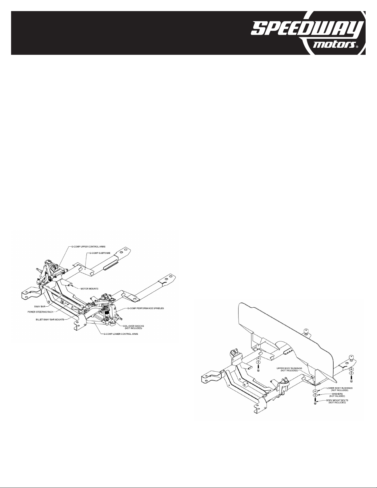
G-Comp Front Suspension
INSTRUCTIONS
© 2019, Speedway Motors, Inc.
Kit Contents:
350-100.2
350-500.1
350-500.2
350-500.3
350-503
910-35000
910-35010
910-35341
910-35500
910-35600
G-Comp Camber Shim Kit
G-Comp Subframe, Camaro
G-Comp Sway Bar Kit, Camaro
Hardware Kit, G-Comp Camaro
G-Comp 34'' Sway Bar
G-Comp Spindles
G-Comp Steering Arms
T-Bird Power Steering Rack
G-Comp Upper Control Arms
G-Comp Lower Control Arms
1. Support the car on jack stands or hoist. The front
stands must be located on the main floor just behind
the firewall. Do not support the car on the front sub-
frame.
2. Remove the hood and inner fenders. Remove the
radiator, front bumper, fenders, and core support.
Disconnect all electrical components from the firewall
forward. Retain all hardware to be used during re-
assembly. Remove the engine, transmission, and
accessories. Support the subframe with a floor jack.
Unbolt the subframe from the body and lower it down
until the weight is supported by the front tires. The sub-
frame can now be rolled out of the way.
3. Install the G-Comp subframe. Now is a good time
to replace your old worn out body mount bushings.
Place the new upper bushing halves into their locations
on the subframe. The rear portion of the subframe
includes body mount locations for both early and later
style Camaros. Be sure to install the bushings into the
appropriate locations for your car. Using a floor jack,
raise the new G-Comp sub-frame into position while
lining up the holes in the sub-frame with the body.
Install new or re-use your OEM body mount bolts along
with the lower body mount bushings and washers.
Note: Start all of the body bolts before tightening
any of them completely. Once all of the bolts have
been started, make sure the subframe is aligned with
the car, and tighten the bolts. With the subframe in
place, you can now move the jack stands to the front
crossmember. This will make the vehicle more stable
while installing the rest of the kit.
2
350-500
70-81 Chevy Camaro
G-Comp Front Suspension
INSTRUCTIONS
© 2019, Speedway Motors, Inc.
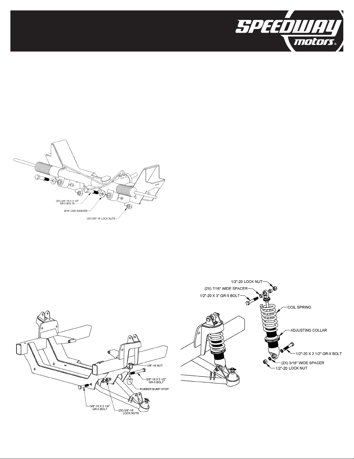
4. Steering Rack. This G-comp front suspension kit
is designed to use a thunderbird style power steering
rack. Install the steering rack as shown, using the two
5/8”-18 x 3 ½” grade 5 bolts and lock nuts. Torque to
65 ft lbs
5. Install the lower control arms into the cross
member. Align the control arm bushings with the lower
control arm holes in the cross-member. The front bolts,
5/8”-18 x 3-1/4” Grade 5, are to be installed from the
front side. The rear bolts are 5/8”-18 x 5-1/2” Grade
5, are to be installed from the rear. Install the 5/8”-
18 lock nuts and torque to 100 ft-lbs. Install the lower
control arm bumps stops to the sub-frame using the
supplied 3/8” nuts as shown.
6. Install the shocks. This procedure may vary slightly
depending on the shocks used. Spin the adjusting
collar onto the threaded shock body. Adjust the collar
all the way to the bottom of the threads. Install the
spring over the shock body. NOTE: The G-Comp
sub-frame has the upper spring retainer built into the
sub-frame so the upper coil-over shock spring retainer
is not used. Using the 1/2”-20 x 2-1/2” Grade 5 bolt and
two 3/16” wide spacers, install the shock into the lower
mount on the control arm. Secure it with a 1/2”-20
Grade 5 lock nut. Fully extend the shock and raise the
lower arm so the upper shock mount and spring align
with the shock mount and spring pocket on the sub-
frame. Install the 1/2”- 20 x 3” Grade 5 upper shock
bolts and 7/16” wide spacers. Secure it with a 1/2”-20
Grade 5 lock nut. Torque to 65 ft-lbs. Note: This kit
is designed to use shocks with a compressed length
of 10” and an extended length of 14”. Shock ends
should be ½” bearings with a mounting width of 1”. For
recommended part numbers please visit our website
or contact one of our tech experts.
3
350-500
70-81 Chevy Camaro
G-Comp Front Suspension
INSTRUCTIONS
© 2019, Speedway Motors, Inc.
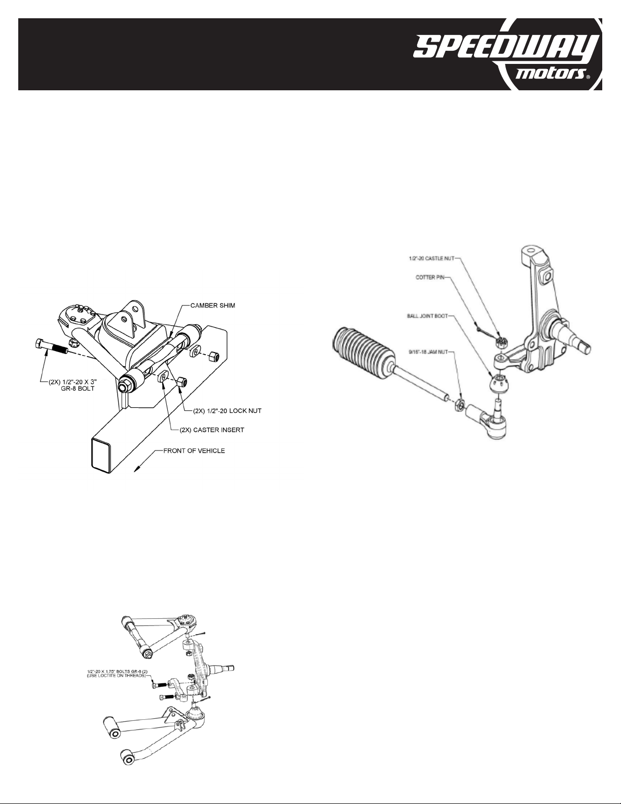
7. Mount the upper control arms to the sub-frame
using the 1/2”-20 x 3” grade 8 bolts and lock nuts.
Rotate the cross shafts so the caster shim pockets are
facing toward the center of the vehicle. Install the bolts
through the caster shims, cross shafts, and the sub-
frame as shown. Then secure with the
1/2”-20 Grade 5 lock nuts. Torque to 72 ft-lbs.
8. Install the spindles and steering arms. Place the ball
joint boots over the ball joints and install the spindle
onto the lower ball joint. Install and tighten the supplied
castle nut. Repeat with the upper ball joints and install
the cotter pins. Bolt the steering arms to the spindles
using the 1/2”-20 x 1-3/4” Grade 8 bolts. NOTE: Make
sure to use Loctite on the threads and torque to 100
ft-lbs.
9. Install the outer tie rod ends and jam nuts onto the
inner tie rods of the rack. Thread both tie rod ends on
equally. Attach the tie rod ends to the steering arms
using the castle nuts supplied with the tie rod ends.
Tighten and install the cotter pins. Final alignment to be
done at a later time.
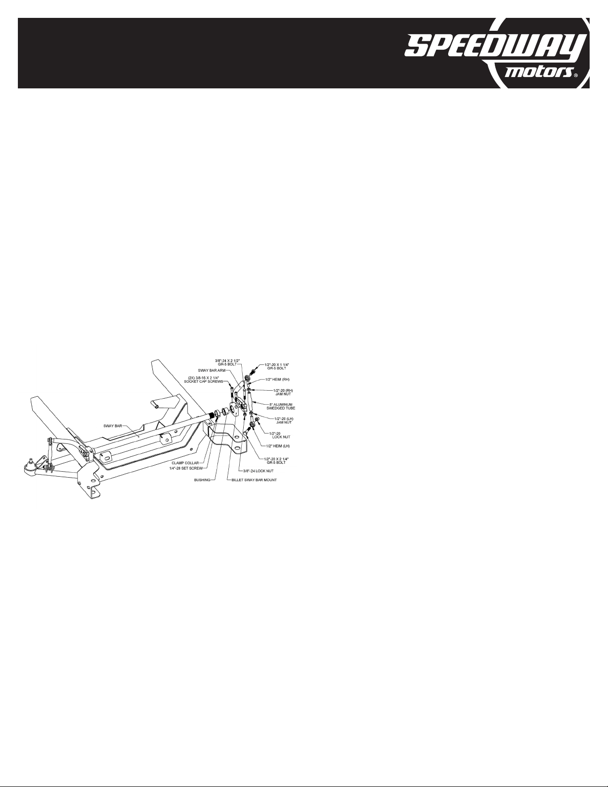
10. Sway bar assembly: Press the bushings into the
aluminum pillow-blocks and install the pillow-blocks
to the front crossmember with the bushing shoulder
to the inside. Use the four 3/8”-16 x 2-1/4” Grade 8
socket head cap screws to secure the pillow block to
the subframe. Before fully tightening the bolts, slide
the sway bar through the bushings, installing the
two clamp collars to the inside of both pillow blocks.
Now, torque the 3/8” socket cap screws to 42 ft-lbs.
Center the sway bar between the pillow blocks. Slide
one clamp collar up against the bushing shoulder in
the pillow block and tighten the set screw. Slide the
second clamp collar up to the opposite bushing in
the pillow block leaving about .075” of side clearance
between the clamp collar and the bushing. Tighten the
set screw. NOTE: A nickel is about .075” thick and can
be used as a spacer between the clamp collar and the
bushing to provide the proper side clearance. Slide
the sway bar arms onto the splined ends of the sway
bar aligning them flush with the end of the bar. Make
4
350-500
70-81 Chevy Camaro
G-Comp Front Suspension
INSTRUCTIONS
© 2019, Speedway Motors, Inc.
sure they are parallel or “clocked” to one another then
tighten the 3/8”-24 x 2-1/2” pinch bolts and lock nuts.
Assemble the sway bar links as shown, leaving roughly
¼” of threads showing on either heim joint. Use the
1/2”-20 x 1-1/4” grade 5 bolts to secure the sway bar
link to the sway bar arm. Mount one of the lower links
into the bracket on the lower control arm using a 1/2”-
20 x 2-1/4” grade 5 bolt and secure it with the 1/2”-20
lock nut. Leave the bolt out of the lower link on one
side at this time. The second bolt/nut will be installed
after the ride height is set and the car is setting on level
ground. This will ensure that there is no preload on the
sway bar at ride height.
11. Install the brake kit to the spindle per the
instructions included with your brake kit. Note: For
recommended part numbers please visit our website
or contact one of our tech experts.
12. Align the subframe: Before installing the front
sheet metal, you must first make sure the subframe is
aligned with the body. Start by setting the toe to zero
and making sure the tires are perfectly straight. Note:
this is easily accomplished with the tires removed and
a 2’-3’ long piece of angle iron clamped to the brake
rotor. Measure the distance between two pieces, both
in the front, and in the rear. Adjust the tie rod length
until the distance is the same. Now measure the wheel
base on both sides of the car. If they are different,
you must loosen the body bolts and slightly adjust the
subframe as needed.
13. Install the engine and transmission. The G-Comp
sub-frame was designed to use stock type GM motor
mounts (910-18012) or Speedway’s Prothane mounts
(910-18015).
14. Install the core support, radiator, grill, and fenders.
All accessories and other components can now be
installed.
15. Alignment. The lower control arms should be
level, with all the weight on the car. To adjust the ride
height, take the weight off the suspension and turn
the threaded adjusters on the bottom of the coil over
shocks. Turning the adjusters clockwise will raise the
ride height. Once the ride height has been set, place
the car back down on level ground. Adjust the free
heim end on the sway bar link so that it lines up with the
bracket in the lower control arm. Keep adjusting the
heim end until the remaining 1/2”-20 x 2-1/4” grade 5
bolt
Set the alignment to the following initial settings:
Caster = 5°
Camber = negative .25°-5°
Toe in = 0''-1/8'' Toe Out
16. Caster adjustments are made by changing the
caster inserts. The caster inserts are identified with
numbers indicating the distance of the hole from the
center of the insert in 1/8” increments.
#1 = 1/8” #2 = 1/4” #3 = 3/8”
The inserts can be reversed to move the hole in front of
or behind center for a total range of ¾”.
17. Camber is adjusted using the included A-arm
shim plates. Additional shim plates can be purchased
separately if desired under Speedway Part # 917-
21005. These are available in thicknesses ranging from
1/8” to 1/2".

SpeedwayMotors.com/Info/FAQ
DISCLAIMER In an effort to offer our customers low prices, quick service
and great value, Speedway Motors reserves the right to change suppliers,
specifications, colors, prices, materials without notice. Prices and policies that
were current and in effect at the time of printing are also subject to change
without notice. Quantities are limited on some items. Any unauthorized use of
this catalog including words, photos or drawings is prohibited. Speedway is not
responsible for any typographical errors, printing errors or misinterpretations
WARRANTY DISCLAIMER Purchasers understand and recognize that racing
parts, specialized street rod equipment, and all other parts and services sold
by Speedway Motors, Inc. are exposed to many and varied conditions due
to the manner in which they are installed and used. Except for certain limited
warranties, if any, set forth in Speedway Motors, Inc.’s current catalog with
respect to the products and/or parts thereof identified on your invoice, each
product,andeachpartthereof,issold“asis”,and“withallfaults”andSpeedway
Motors, Inc. makes no warranties either expressed or implied, written or
oral, with regard such products and services including, without limitation,
any warranty of merchantability or fitness for a particular purpose. Without
limiting the foregoing, there is no warranty expressed or implied as to whether
the goods sold hereby will protect purchasers or ultimate end-users of such
products and parts from injury or death. In no event shall Speedway Motors,
Inc. be liable for any special, incidental or consequential damages, or any other
damages whatsoever arising out of or connected with the use or misuse of the
products and each part thereof. Purchasers acknowledge and agree that no
person, entity or agent of Speedway Motors, Inc. has any authority to make
any statement contrary to this disclaimer and that any warranty statements
or representations allegedly made on behalf of Speedway Motors, Inc. by any
such person, entity or agent are void. Purchasers are relying solely on their own
skill and judgment to select, purchase and use suitable products and assume
all responsibility and risk with regard thereto. Some local laws prohibit the use
of utility jugs, funnels and barrel pumps for dispensing fuel. Please check your
own state for more information, regulations or further direction in your use of
the utility jugs, funnels and barrel pump described in Speedway’s catalogs or
on Speedway Motors websites. Some parts in this catalog are not legal for sale
or use in California. Items sold in this catalog are for racing vehicles which may
never be used on a highway. The use of manufacturer’s names and symbols
are for reference purposes only.
DAMAGE CLAIMS Please inspect all packages upon delivery and in the
presence of the delivery driver when possible. The driver must note any visible
damage and provide procedures for handling damage claims. To allow for a
claims process, please retain original box, packing material and damaged
merchandise. Contact Speedway Motors for instructions regarding damage
claim within 5 days of receipt. Speedway Motors assumes no liability after
this period.
SHORTAGES Please check the contents of your delivery to ensure that all
parts ordered are received. Refer to your invoice to cross check all items
received and inspect all packing materials for contents of small items. Retain
original shipping box and packing materials. Orders may be split into multiple
boxes which can be delivered on different days. Contact Speedway Motors
for instructions regarding shortage claim within 5 days of receipt. Speedway
Motors assumes no liability after this 5 day period.
REFUSALS All refused packages will be billed the freight to and from the
destination and refused COD orders will be billed a 15% restocking charge plus
freight to and from destination.
WARRANTY CLAIMS If the item is used or installed and a warranty claim
request is submitted, warranty work is done by the manufacturer and may
take up to 30 days for processing. Speedway Motors will be required to
follow the manufacturer’s warranty instructions to allow for a credit refund or
exchange when specified.
RETURNS We want you to be satisfied with your purchase. If you are not
satisfied, you may return your new, unused item within 60 days for refund or
exchange.
All exchanged or returned merchandise must be in original factory condition
with no modifications or alterations. Returned merchandise must include
original packaging materials, warranty cards, manuals, instructions, etc. If the
returned item requires repackaging, your refund / exchange will be subject
to a repackaging charge. Return/Exchange transactions less than $99 are
excluded from the free shipping offer.
HOW TO RETURN AN ITEM Please re-pack the item in a sturdy box, include
a copy of your invoice and completed return form. Returns must be shipped
prepaid. CODs are not accepted. Shipping costs for exchanged merchandise
will be charged to your credit card.
Items that are returned after 60 days are subject to a 15% restocking charges.
Fiberglass items returned will be subject to a 15% restocking charge. We are
unable to accept returns on electrical parts, video tapes, DVD’s, books, special
order or closeout merchandise.
BRAKE INSTALLATION ALERT The selection and installation of brake
components should only be done by personnel experienced in the proper
installation and operation of braking systems. The installer must use his/
her own discretion to determine the suitability of all brake components
and brake kits for every particular application. Speedway Motors, Inc.
makes no warranties either expressed or implied including any warranty of
merchantability or fitness for a particular purpose, other than those contained
in its current catalog or website with respect to the goods identified on the
face of the invoice. There is no warranty expressed or implied as to whether
the goods sold hereby will protect the purchaser or ultimate user of such
goods from injury of death.
EXHAUST INSTALLATION ALERT Exhaust systems and other component
surface finishes are not permanent. Coatings, paint and other factory supplied
cosmetic treatments are only intended to protect from surface corrosion in
an unused state. No returns are allowed after the parts have been installed.
Header flanges must be clean and clear of paint and surface contaminants
prior to mating to exhaust gaskets. Exhaust fasteners must be re-torqued
after the initial heat cycle and regularly thereafter to ensure a proper gasket
seal is maintained. Should you decide to install this exhaust product at your
home, be warned that pleasure car or light duty truck/van “bumper” jacks
are intended for emergency use only. The use of frame contact jack stands
in conjunction with a floor jack as a main support is highly recommended to
minimize accidental dropping of a vehicle while the installation proceeds. We
recommend the use of a shop hoist if possible. Please use caution! Speedway
Motors, Inc. makes no warranties either expressed or implied including any
warranty of merchantability or fitness for a particular purpose, other than
those contain in its current catalog or website with respect to the goods
identified on the face of the invoice. There is no warranty expressed or implied
as to whether the goods sold hereby will protect the purchaser or ultimate user
of such goods from injury or death.
CHECK LOCAL LAW Some parts are not legal for sale or use in California on
any pollution controlled motor vehicles. These items are legal in California for
racing vehicles only which may never be used upon a highway. Check local
law.
Speedway Motors, Inc.
P.O. Box 81906 • Lincoln, NE 68501
800.979.0122 • SpeedwayMotors.com
Find the above info on our website:
© 2019, Speedway Motors, Inc.
IMPORTANT
Other Speedway Automobile Accessories manuals


Popular Automobile Accessories manuals by other brands


ULTIMATE SPEED
ULTIMATE SPEED 279746 Assembly and Safety Advice

SSV Works
SSV Works DF-F65 manual

ULTIMATE SPEED
ULTIMATE SPEED CARBON Assembly and Safety Advice

Witter
Witter F174 Fitting instructions

WeatherTech
WeatherTech No-Drill installation instructions

TAUBENREUTHER
TAUBENREUTHER 1-336050 Installation instruction