Spellman LORAD LPX-200 User manual

LPX200

118176-001 REV. A
Copyright 2000, Spellman High Voltage Electronics Corporation. All Rights Reserved.
This information contained in this publication is derived in part from proprietary and patent data. This information has
been prepared for the express purpose of assisting operating and maintenance personnel in the efficient use of the
model described herein, and publication of this information does not convey any right to reproduce it or to use it for
any purpose other than in connection with installation, operation, and maintenance of the equipment described.
CAUTION: THIS EQUIPMENT PRODUCES
X-RAYS WHEN ENERGIZED!
DO NOT OPERATE THIS EQUIPMENT WITHOUT
FORMAL HARDWARE RAINING FROM
SPELLMAN HIGH VOLTAGE ELECTRONICS.
ASNT LEVEL 3 RADIOGRAPHIC CERTIFICATION
IS HIGHLY RECOMMENDED.
WWW.SPELLMANHV.COM

i
Table of Contents
LPX-200
Industrial Ima
g
in
g
S
y
stem
Copyright Notice
Copyright© 2002 by LORAD All rights reserved.
COPYRIGHT NOTICE
This document is copyrighted by LORAD.
No part of this document may be reproduced, transmitted,
or copied without the express written permission of:
LPX-200 Industrial Imaging System
Operator’s Manual
Part Number 9-500-0200, Revision 2
Spellman Valhalla 1 Commerce Park Valhalla, NY 10595
Phone: +1 914 686-3600 Fax: +1 914 686-5424
www.spellmanhv.com

ii
Table of Contents
LPX-200
Industrial Ima
g
in
g
S
y
stem
This Page Is Intentionally Blank

iii
Table of Contents
LPX-200
Industrial Ima
g
in
g
S
y
stem
Contents
1
Chapter INTRODUCTION & GENERAL INFORMATION
INTRODUCTION ..................................................................1-1
Intended Use.........................................................................1-1
SYSTEM OVERVIEW ..........................................................1-1
The Control Unit...................................................................1-2
The Tubehead .......................................................................1-2
The Cooling Unit
(liquid-cooled units only) .....................................................1-2
Legend - LPX-200 X-ray System ..........................................1-3
MANUAL OUTLINE .............................................................1-4
Chapter 1:
Introduction & General Information....................................1-4
Chapter 2:
Preparation For Use and Shipment......................................1-4
Chapter 3:
Installing the LPX-200 .........................................................1-4
Chapter 4:
LPX-200 X-ray Controls & Indicators .................................1-4
Chapter 5:
LPX-200 X-ray System Operation ........................................1-4
Section 6:
Routine Upkeep and Care ....................................................1-4
SAFETY SUMMARY ............................................................1-5
Radiation Hazard .................................................................1-6
Lethal Voltages .....................................................................1-6
Badges ..................................................................................1-6
Radiation Protection ............................................................1-6
Radiation Monitoring...........................................................1-6
Warm-Up Procedures ...........................................................1-6
Operation .............................................................................1-6
Cooling Unit Operation .......................................................1-6
Care in Handling..................................................................1-6

iv
Table of Contents
LPX-200
Industrial Ima
g
in
g
S
y
stem
UNPACKING INSTRUCTIONS...........................................2-1
Reshipment Guidelines .........................................................2-1
Transporting the Unit ...........................................................2-2
EQUIPMENT CHECKLISTS...............................................2-3
Checklist - Tubehead ............................................................2-3
Checklist - Standard Equipment ...........................................2-3
Checklist - Optional Equipment ...........................................2-3
WARNINGS LABELS &
CONTROL NUMBERS .........................................................2-4
SPECIFICATIONS.................................................................2-5
Specifications - General System ...........................................2-5
Specifications - General Tubehead.......................................2-6
Specifications - Optional Tubehead .....................................2-6
Specifications - Control Unit................................................2-7
Specifications - Cooling Unit ...............................................2-7
2
Chapter
3
Chapter
PREPARATION FOR USE & SHIPMENT
INSTALLING THE LPX-200 X-RAY SYSTEM
PRE-OPERATIONAL
CHECKS & INSPECTION ...................................................3-1
Check - Tubehead Gas Pressure...........................................3-1
Check - Cooling Unit............................................................3-1
Check - Control Unit ............................................................3-1
SYSTEM SET UP PROCEDURES.......................................3-2
System Interconnections - Liquid Cooled.............................3-2
System Interconnections - Air Cooled ..................................3-3
Connecting to Power ............................................................3-4
EXTERNAL
INTERLOCK CONNECTIONS ...........................................3-4

v
Table of Contents
LPX-200
Industrial Ima
g
in
g
S
y
stem
INTRODUCTION ..................................................................4-1
Overview - Control Unit .......................................................4-1
Legend - LPX-200 Control Unit ...........................................4-1
THE LIQUID
CRYSTAL DISPLAY SCREENS ..........................................4-2
The Message / Mode LCD Display Screen ...........................4-3
FRONT PANEL
CONTROLSAND INDICATORS ........................................4-4
The MAINS Switch................................................................4-4
The MAINS ON Indicator.....................................................4-4
The SAFETY Switch..............................................................4-4
The kV SET Controls ............................................................4-4
The mA SET Controls ...........................................................4-4
The EXPOSURE SET Controls ............................................4-5
The UNITS Control...............................................................4-5
The TIME Control ................................................................4-5
The RESET Control ..............................................................4-5
The SCROLL Control ...........................................................4-6
The X-RAY ON Control ........................................................4-6
The X-RAY Indicator ............................................................4-6
The X-RAY OFF Control ......................................................4-6
4
Chapter
5
Chapter
LPX-200 X-RAY CONTROLS & INDICATORS
LPX-200 SYSTEM OPERATION
INTRODUCTION ..................................................................5-1
Pre-Operational Safety Precautions ....................................5-1
X-RAY TUBE WARM UP......................................................5-2
Autowarm Sequence : > 30 Days.........................................5-2
Autowarm Sequence : 7 - 30 Days .......................................5-3
Autowarm Sequence : 16 Hrs. - 7 Days ...............................5-3
Autowarm Sequence : 8 Hrs. - 16 Hrs..................................5-4
Autowarm Sequence : 4 Hrs. - 8 Hrs....................................5-4
OPERATION -
LPX-200 X-RAY SYSTEM ....................................................5-5
Sequence of Operation .........................................................5-5
LPX-200 FAULT MESSAGES...............................................5-7
X-RAY TUBE SEASONING .................................................5-8

vi
Table of Contents
LPX-200
Industrial Ima
g
in
g
S
y
stem
6
Chapter
LPX-200 ROUTINE UPKEEP & CARE
INTRODUCTION ..................................................................6-1
INSPECTION CHECKLISTS ..............................................6-1
Tubehead Checklist ..............................................................6-1
Control Unit Checklist..........................................................6-2
Cooling Unit Checklist .........................................................6-2
Interconnecting Cables & Hose Checklist ...........................6-2
CLEANING THE
LPX-200 X-RAY UNIT ..........................................................6-3
Required Cleaning Materials ...............................................6-3
Cleaning the X-Ray Unit ......................................................6-3
TUBEHEADMAINTENANCE ............................................6-4
Temperature Compensation..................................................6-4
Re-Pressurizing the Tubehead .............................................. 6-5
Re-Filling the Tubehead .......................................................6-6
Cleaning - Control Unit Air Filter........................................6-6
COOLING UNIT UPKEEP...................................................6-7
Mixing & Adding Coolant Solution......................................6-7
Cleaning - Cooling Unit Air Filter .......................................6-7
Cleaning - Coolant Filter .....................................................6-8
1-1
Chapter 1:Introduction & General Information
LPX-200
Industrial Ima
g
in
g
S
y
stem
Chapter 1:
Introduction and General Information
INTRODUCTION
This manual describes the LORAD LPX-200 Portable
Industrial X-ray Unit and explains the procedures to properly
set up, inspect, operate, and maintain this system.
Intended Use
The LPX-200 is designed to meet the needs of the commercial
NDT user. The system is intended for, but not limited to, the
inspection of materials for:
◆defects
◆inclusions
◆cracks
◆corrosion
◆porosity
SYSTEM OVERVIEW
The LPX-200 can generate x-ray potential up to 200 kilovolts
(kV) and tube current up to 10 milliamperes (mA). The
maximum allowable dissipation is 900 watts. Maximum tube
current is limited automatically by the Control Unit to 10mA,
or to a value that does not cause dissipation greater than 900
watts at a set kV level.
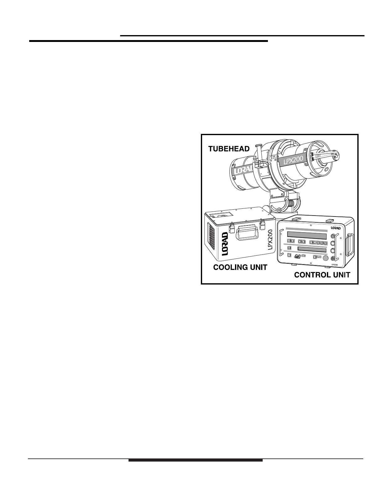
The system offers a 100% duty cycle and consists of the
following assemblies:
◆the Control Unit
◆the Tube Head
◆the Cooling Unit, (liquid cooled units only)
◆the Electric Cooling Fan (air cooled units only)
These assemblies are described in detail next.
Figure 1-1:
The LPX-200 X-ray System

1-2
Chapter 1:Introduction & General Information
LPX-200
Industrial Ima
g
in
g
S
y
stem
The Control Unit
The radiographer uses the Control Unit to set the radiographic
exposure parameters, and to activate/deactivate x-ray
emissions from the Tubehead. One hundred feet of cable is
supplied with the system, which enables the Control Unit an
operator to maintain a safe distance from the x-ray Tubehead
during use.
The digital-based, microprocessor-regulated Control Unit
houses all the system pushbutton operating controls, an
exposure factor LCD Screen (for display of exposure factors),
a Message LCD Screen (for display of operating mode and
system messages), and the circuitry required to provide power
to the Tubehead and Cooling Unit.
The Control Unit is enclosed in a metal container with a
removable cover. A collapsible handle is attached to the cover
to provide a means of transporting the Control Unit.
TheTubehead
The Tubehead is a cylindrical aluminum shell assembly
housing the x-ray tube, the high voltage power supply, and the
filament supply. It is insulated with sulfur hexafluoride gas,
pressurized to 50 psi @70°F. Power to operate the x-ray tube
is supplied through a shielded cable that connects the
Tubehead to the Control Unit. The x-ray tube is end
grounded, with an exposed anode which contains a beryllium
window approximately 2 inches from the anode end. Built in
carrying handles are at each end of the Tubehead.
There are two Tubehead models available:
◆Liquid-cooled
◆Air-cooled
The liquid-cooled Tubehead uses a separate Cooling Unit to
dissipate anode heat. These models have a length of twin hose
attaching the Tubehead to the Cooling Unit. Air-cooled
models have an electric cooling fan mounted at the anode end
of the Tubehead. The fan is powered by an interconnecting
cable from the Control Unit.
The Cooling Unit
(liquid-cooled units only)
The Cooling Unit dissipates heat generated at the anode of the
x-ray tube. Liquid coolant from a self-contained reservoir is
pumped through one side of a twin hose assembly, into the
Tubehead. In the Tubehead, coolant flows through a cooling
manifold, into the anode, and then back to the Cooling Unit
through the second half of the twin hose assembly.
Once in the Cooling Unit, coolant passes through a flow
switch that is electrically interlocked with the Control Unit,
and then through a filter to screen out contaminants. From the
filter, coolant flows through a forced air radiator, where
conducted heat is dissipated, and then back into the reservoir.
An electric motor-driven fan and pump assembly circulates
coolant and creates airflow through the radiator. Power is
supplied via an interconnecting cable from the Control Unit.
When properly connected to the system, the Cooling Unit is
automatically activated by a switching circuit within the
Control Unit.
1-3
Chapter 1:Introduction & General Information
LPX-200
Industrial Ima
g
in
g
S
y
stem
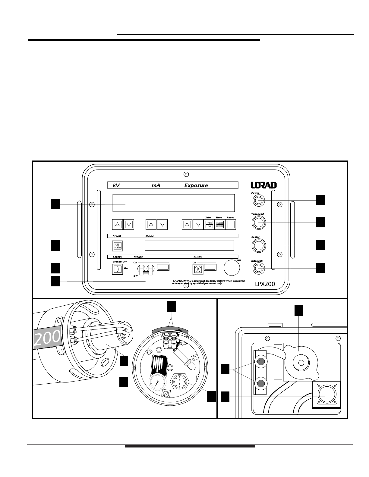
Legend - LPX-200 X-ray System
Use the following legend as a reference for parts
idnetification.
1. Exposure Technique LCD Display
2. Message LCD Display
3. Power Connector
4. Tubehead Connector
5. Cooler Connector
6. Interlock Connector
7. Mains On/Off Switch
8. Lockout Keyswitch
9. Tubehead Anode
10. Tubehead Coolant Hose Fittings
11. Tubehead Gas Pressure Gauge
12. Tubehead Cable Connector
13. Cooling Unit Reservoir Cap
14. Cooling Unit Coolant Hose Fittings
15. Cooling Unit Cable Connector
Figure 1-2:
Legend - LPX-200
1
2
3
4
5
6
7
8
9
10
11
12
13
14
15
CONTROL
UNIT
TUBEHEAD
ASSEMBLY
COOLING
UNIT

1-4
Chapter 1:Introduction & General Information
LPX-200
Industrial Ima
g
in
g
S
y
stem
MANUAL OUTLINE
This manual provides qualified radiographers and technicians
with a means to logically inspect, operate, and maintain the
LORAD LPX-200 Portable X-ray Unit. The following
paragraphs describe the arrangement of this manual and the
information contained in each section.
Chapter 1:
Introduction & General Information
This section provides general information about the LPX-200.
Included in this section is a safety summary.
Chapter 2:
Preparation For Use and Shipment
In this chapter, the user is provided instructions for unpacking
and reshipment, along with equipment checklists, and the
basic specifications of for assembly. Also included in
Chapter 2 are the locations of warning labels and I.D. tags.
Chapter 3:
Installing the LPX-200
This chapter provides instructions on making the
interconnections for both liquid cooled and air cooled units.
Also includes is a description of possible external interlock
connections.
Chapter 4:
LPX-200 X-ray Controls & Indicators
Chapter 4 details the controls and indicators on the LPX-200
Control Unit. Refer to this chapter during use for operational
details.
Chapter 5:
LPX-200 X-ray System Operation
The warm up and operating instructions for the LPX-200
X-ray Unit are detailed in Chapter 5. Included are
descriptions of error messages.
Section 6:
Routine Upkeep and Care
This chapter covers preventive maintenance and care
schedules for each assembly of the system. Included are
procedures for pressurizing and refilling the Tubehead,
cleaning the apparatus, and various general care practices.

1-5
Chapter 1:Introduction & General Information
LPX-200
Industrial Ima
g
in
g
S
y
stem
SAFETY SUMMARY
When properly installed, maintained, and operated, X-ray
equipment can be used effectively and safely. If any
component of this unit is incorrectly installed, and/or operated
by unqualified personnel, or if the maintenance schedule is
neglected, it is a potentially dangerous apparatus.
Before operating or performing any maintenance on the
LPX-200, the user MUST have a thorough understanding of
x-ray machinery, x-ray generation, x-ray potential, and x-ray
control. The user MUST understand all hazards associated
with x-ray generation.
Read this “Safety Summary” completely, and thoroughly
understand its contents. Read all of the safety warnings,
cautions, and notes throughout this manual prior to
commencing any operating or maintenance procedures.
All operators and technicians MUST adhere to the following
safety practices:
◆Read and understand the x-ray protection warning
published at the front of this manual.
◆Read this manual in its entirety.
◆Understand and all procedures completely before
operating the unit.
◆Read thoroughly and understand completely all
NOTE, CAUTION, and WARNING statements
before beginning operation or maintenance
procedures.
Use the following summary as a checklist to assure
comprehension of the safety indicators.
NOTE:
An essential operating procedure, condition, or
statement, which must be observed to ensure proper
understanding and operation of the system.
! CAUTION !
An operating or maintenance procedure,
practice, condition, or statement, which, if
not strictly observed, could result in
damage to, or destruction of equipment.
! WARNING !
An operating or maintenance
procedure, practice, condition, or
statement, which, if not strictly
observed, could result in injury to or
death of personnel.

1-6
Chapter 1:Introduction & General Information
LPX-200
Industrial Ima
g
in
g
S
y
stem
Radiation Hazard
This equipment generates X-radiation at levels that can be
lethal. This unit must only be operated by personnel that are
certified and experienced in industrial x-ray generation. All
operators must also understand the characteristics of radiation
and the associated dangers of exposure to primary, secondary,
and residual sources of radiation.
Lethal Voltages
High power radiation sources depend upon the generation of
extremely high, yet well-protected voltages. Under no
circumstances should the operator access the interior of the
Tubehead. Also, under no circumstances should the operator
access the interior of the Control Unit or the Cooling Unit
except for the procedures outlined in Section 5 of this manual.
Badges
All personnel who work around X-ray equipment must wear a
functional exposure dosage indicator.
Radiation Protection
X-ray equipment must be operated within properly designated
protective barriers. Otherwise, personnel must not approach
closer than 100 feet from the Tubehead, and in no cases cross
the direct path of the primary beam.
Radiation Monitoring
After installation, re-installation, transporting, performing
maintenance, and during all radiographic operations not
within a radiation enclosure, a radiation survey should be
performed.
Warm-Up Procedures
Explicit procedures are outlined for “running-up” high voltage
with new equipment, equipment with a new tube, equipment
that has been inactive for a period of time, and for daily use.
These procedures must be strictly followed at all times.
Operation
Equipment must be operated at correct source voltage and
frequency, and must never be left running unattended. The
gas pressure in the Tubehead must be checked to ensure it is
within allowable limits before operating the unit. Never
operate this apparatus if output voltage/current is unstable.
Cooling Unit Operation
Regularly check the coolant solution in the Cooling Unit to
ensure:
◆the coolant level is within specification
◆the pump circulates the coolant properly
◆the fittings, hoses, and coolant reservoir does not leak
Always allow the Cooling Unit, or the fan on air-cooled units,
to run approximately 5 minutes after completion of x-ray
generation.
Care in Handling
Extreme care must be taken when handling this x-ray
apparatus. Exercise caution when packing, unpacking,
shipping, and while performing maintenance. Remember, the
X-ray tube is durable but breakable: be sure to store and ship
it in the upright position.

LPX-200
Industrial Ima
g
in
g
S
y
stem
2-1
Chapter 2:Preparation for Use and Shipment
Chapter 2:
Pre
p
aration for Use and Shi
p
ment
UNPACKING INSTRUCTIONS
The LPX-200 X-ray Unit is shipped in a single wooden
container. To gain access to the unit, perform the following:
◆Remove the top cover from the crate.
◆Carefully lift each component from the container.
◆Perform a thorough visual inspection on each
component.
If damage to any component has occurred, immediately
contact the carrier. Keep all damaged containers until the
carrier completes an inspection by the carrier. If it is
necessary to re-package and ship the unit, follow the
instructions outlined under “Reshipment Guidelines”.
Reshipment Guidelines
In the event that the LPX-200 X-ray Unit must be transported
or shipped, use the original wooden container and packaging
material whenever possible. If the original shipping material
is not available, comply with the following re-packing
guidelines.
1. Construct a wooden shipping carton for the
Tubehead Assembly similar to the one in Figure 2-1.
Build the carton so that the top can be completely
removed to facilitate packing and unpacking.
2. Cushion the Tubehead with 3" of shock absorbent,
foam type, packing material (MINIMUM). This
material MUST surround the assembly on all sides,
including above and below the Tubehead.
3. Affix supporting legs to the bottom of the carton.
Make sure the legs extend between 7 and 10 inches
from the edges as shown in Figure 2-1.
4. Pack the Control Unit in a container rated for 60 lbs.
Surround the Control Unit with a MINIMUM of 2"
of shock absorbent packing material (sheet or loose
type), including the top and bottom.
5. Pack the Cooling Unit in the same manner as the
Control Unit.
! WARNING !
The coolant solution is a flammable
substance and must be drained from
the Cooling Unit’s reservoir before it
can be shipped.

LPX-200
Industrial Ima
g
in
g
S
y
stem
2-2
Chapter 2:Preparation for Use and Shipment
Transporting the Unit
When transporting by commercial carrier (i.e., truck, rail,
etc.), select the shipping method and carrier on the basis of
safe shipment, especially when shipping the fragile Tubehead
Assembly. Distinctly mark the Tubehead carton on all sides
with labeling which provides the carrier the following
information:
◆Contents contains fragile glass instrumentation
◆Container is to be shipped in the upright position
only
Customarily, the Tubehead is shipped via air, generally
avoiding ground transportation if possible. When shipping via
air, affix an additional label to the carton stating the following:
“Sulfur hexafluoride, non-flammable gas is
present in limited quantities in one or more
packages of this shipment. This is to certify that
the above mentioned materials are properly
classified, described, packaged, marked, and
labeled, and are in proper condition for
transportation according to the applicable
regulations of the U.S. Department of
Transportation.”
Figure 2-1:
Tubehead Shipping Container
Removeable
Top
Support
Leg
Support
Leg
Support
Leg
Warning
Label
Fragile
Instrument
Label
SF6 Label

LPX-200
Industrial Ima
g
in
g
S
y
stem
2-3
Chapter 2:Preparation for Use and Shipment
EQUIPMENT CHECKLISTS
The following checklists outline the standard and optional
equipment of the LPX-200 X-ray Unit. After unpacking the
unit, and completing a thorough visual inspection, compare
each item with this list to assure completeness.
Note that several Tubehead models are available. Verify that
the Tubehead shipped with your unit matches the model that
was originally ordered.
Checklist -Tubehead
❏Assembly, Tubehead* ______ 3-000-3071
Air Cooled Unit; 40°x 60°cone
1.5mm Focal Spot
1mm Beryllium Window
❏Assembly, Tubehead _______ 3-000-3072
Liquid Cooled; 40°x 60°cone
1.5mm Focal Spot
1mm Beryllium Window
❏Assembly, Tubehead _______ 3-000-3073
Liquid Cooled; 360°Panoramic
0.4mm x 4.0mm Focal Spot
0.4 Fe/Ni/Co Window Tube
* All Air Cooled Units are equipped with Fan Power
Cable (p/n: 1-040A-0355). The liquid Cooling Unit
is not equipped with this cable.
Checklist - Standard Equipment
❏Control Unit, Digital (1) ____ 3-000-3074
❏Cooling Unit Assembly (1) __ 3-000A-0737
(Liquid Cooled Units Only)
❏Power Cable Assembly (1) __ 1-040A-0825
(3 Pin Connector, 25ft.)
❏Power Cable Assembly (1) __ 1-040A-0831
(3 Pin Connector, 100ft)
❏Control Cable Assembly (1) _ 1-040A-0824
(14 Pin Connector, 100ft.)
❏Cooler Power Cable (1)_____ 1-040A-0823
(Liquid Cooled Units Only, 8 Pin
Connector, 50ft.)
❏Power Cable, Fan (1)_______ 1-040A-0355
(Air Cooled Units Only, 100ft.)
❏Interlock Jumper (1) _______ 3-000-3075
(Jumper)
❏Safety Switch Key (2) ______ 2-230-6201
❏Interlock Connector (1) _____ 1-600-3218
(Mating Connector)
Checklist - Optional Equipment
❏X-Ray Tubehead Stand _____ 3-000A-0754
❏Kit, Tubehead Re-charge ____ 9-200A-0102
❏Laser Pointer _____________ 3-000-0792
❏Laser Pointer Adapter ______ 3-100-0175
LPX-200
Industrial Ima
g
in
g
S
y
stem
2-4
Chapter 2:Preparation for Use and Shipment
WARNINGS LABELS &
CONTROL NUMBERS
Each assembly of the LPX-200 X-ray System is equipped
with an I.D. tag (Control Tag) providing the serial number,
description, and part number. This data is used for
identification, if warranty or service information is needed,
and will be requested when contacting LORAD regarding the
apparatus.
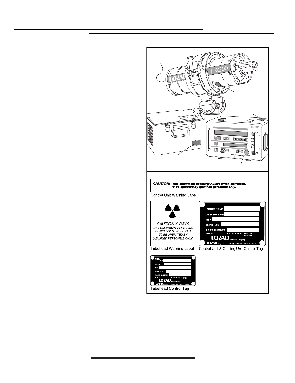
Attached to the Control Unit and Tubehead are warning labels.
Figure 2-2 illustrates the location of the I.D. tags and warning
labels for each assembly of the LPX-200.
Figure 2-2:
Location ofWarning Labels and ControlTags
Warning Label
Warning Label
Control Tag
Control Tag
Control Tag
eeeeeeeeeeeeeeeeee
eeeeeeeeeeeeeeeeee
eeeeeeeeeeeeeeeeee
eeeeeeeeeeeeeeeeee
eeeeeeeeeeeeeeeeee
eeeeeeeeeeeeeeeeee
eeeeeeeeeeeeeeeeee
eeeeeeeeeeeeeeeeee
eeeeeeeeeeeee
eeeeeeeeeeeee
eeeeeeeeeeeee
eeeeeeeeeeeee
eeeeeeeeeeeee
eeeeeeeeeeeee
eeeeeeeeeeeee
eeeeeeeeeeeee
eeeeeeeeeeeee
eeeeeeeeeeeee

LPX-200
Industrial Ima
g
in
g
S
y
stem
2-5
Chapter 2:Preparation for Use and Shipment
SPECIFICATIONS
The following tables illustrate the physical, operational, and
environmental specifications for each component of the
LPX-200 System. Conformance with these specifications
ensures maximum system performance, and reduces the
chances of mechanical breakdown and personnel hazard.
Specifications - General System
The following outlines the general operating and
environmental limits of the LPX-200 System.
❏Line Voltage * ____________ 100 to 130 VAC - 50/60 Hz, 20
amps (maximum); or 200 to 250
VAC - 50/60 Hz, 10 amps
(maximum)
❏ Operating Potential ________ 10kV to 200kV @ 0.1 to 10.0
mA, 900 Watts maximum
❏ Duty Cycle ______________ 100%
❏ Operating Temperature Range -30°F to 120°F (Ambient)
-34°C to 49°C (Ambient)
❏ Humidity ________________ 0 to 100% relative humidity
❏ Stabilization______________ kV and mA remain within 1% of
set levels. Line voltage varied
from 100-130/200-250 VAC.
❏ Storage Temperature Range _ -65°F to 160°F (-54°C to 71°C)
* Line voltage selection is automatic. The system is
operable from either line voltage range without any
switch or jumper configuration.
Figure 2-3:
LPX-200 MaximumTube Current
5.0
10.0
9.0
8.2
7.5 6.9 6.4 6.0 5.6 5.3 5.0 4.7 4.5

LPX-200
Industrial Ima
g
in
g
S
y
stem
2-6
Chapter 2:Preparation for Use and Shipment
Specifications - GeneralTubehead
The following outlines the general operating specifications of
the Tubehead Assembly.
❏ Physical Specifications _____ Water Cooled: 8.5" dia. x 26.5"
length - 32lbs (approx); Air
Cooled: 8.5" dia. x 29" length -
36 lbs (approx)
❏ Anode Cooling System _____ Recirculating Liquid Cooling unit
or Fan Forced Air
❏ Radiation Output __________ 20R/minute @200kV, 4.5mA @
50cm through 0.5 in. of
Aluminum
❏ Leakage Radiation_________ 0.8 R / hr
❏ Tube Pressure Sense _______ Monitors pressure of the SF6 gas
within the Tubehead. Shuts unit
down if pressure falls below 25
psi.
❏ Anode Thermal Sense ______ Monitors temperature of the X-ray
Tube Anode. Shuts down unit if
Anode temperature rises above
220°F.
❏ Pressure Relief Valve_______ Automatically releases SF6 gas
from Tubehead if pressure rises
between 75 - 80 psi.
❏ Pressure Gauge ___________ Displays SF6 gas pressure within
Tubehead. Used in conjunction
with Temperature Compensation
chart to visually inspect Tubehead
pressure.
Specifications - OptionalTubehead
The information that follows furnishes the specifications for
several available Tubehead assemblies. Figure 2-4 illustrates
the direction of the X-ray beam for both the 40°x 60°cone
and the 360°panoramic models.
❏ Tubehead 40°x 60°Cone ___ Air or liquid cooled models;
1.5mm Focal spots; 1mm
beryllium window
❏ Tubehead 360°Panoramic __ Liquid cooled, 0.4mm x 4.0mm
focal spot, 0.4 Fe/Ni/Co window
only
Figure 2-4:
X-ray Beam Path
DIRECTIONALTUBE HEADDIRECTIONALTUBE HEAD
PANORAMIC (360˚)TUBE HEAD
60˚
40˚
44˚
Table of contents
Other Spellman All In One Printer manuals


