Spelsberg Pure 591 415 01, Pure 591 417 01, Pure 591 515 01, Pure 591 517 01 Smart 591 435... User manual

Betriebs- und Installationsanleitung
Operating and Installation Guide
safe.inspiring.green.
Für weitere Informationen besuchen Sie uns
auf www.spelsberg.de/support/wallbox
For more information visit us at
www.spelsberg.com/support/wallbox

2
Zu dieser Anleitung
About the manual
Lesen Sie diese Anleitung vor der Bedienung
sorgfältig durch und bewahren Sie diese auf.
Geben Sie diese im Falle einer Weitergabe des
Produktes an den Benutzer weiter. Weiterführende
Informationen zum Produkt, Details und technisches
Wissen finden Sie auf unserer Webseite.
Hinweis: Dieses Dokument beinhaltet
Informationen für die Elektrofachkraft
und den Benutzer. Es enthält u.a. wichtige
Hinweise zur Installation und zum ordnungsge-
mäßen Gebrauch des Produkts und gilt für
alle Spelsberg Wallbox Varianten.
Bedeutung der Symbole:
Gefahr
Nichtbeachtung führt zu Tod oder
schweren Verletzungen
»Vermeiden der Gefahr
Warnung
Nichtbeachtung führt zum Tod oder
schweren Verletzungen
»Vermeiden der Gefahr
Achtung
Nichtbeachtung kann zu
Sachschäden führen
»Vermeiden der Beschädigung
Hinweis
Erläuterung Hinweis
Wichtige ergänzende Information
Read these instructions carefully before assembly
and operation and keep them in a safe place.
Give them to the new user if the product is passed
on. More information on the product, details and
technical knowledge can be found on our website.
Note: This document contains
information for the electrician and
the user. It includes important Instructions for the
installation and proper use of the product and
applies to all Spelsberg Wallbox variants.
Meaning of the symbols
Danger
Failure to comply may result in death
or serious injury.
» Avoid the danger.
Warning
Failure to comply may result in death
or serious injury.
» Avoid the danger.
Attention
Failure to comply may
result in injury.
»Avoid the damage.
Note
Explanatory note
Important additional information.
3
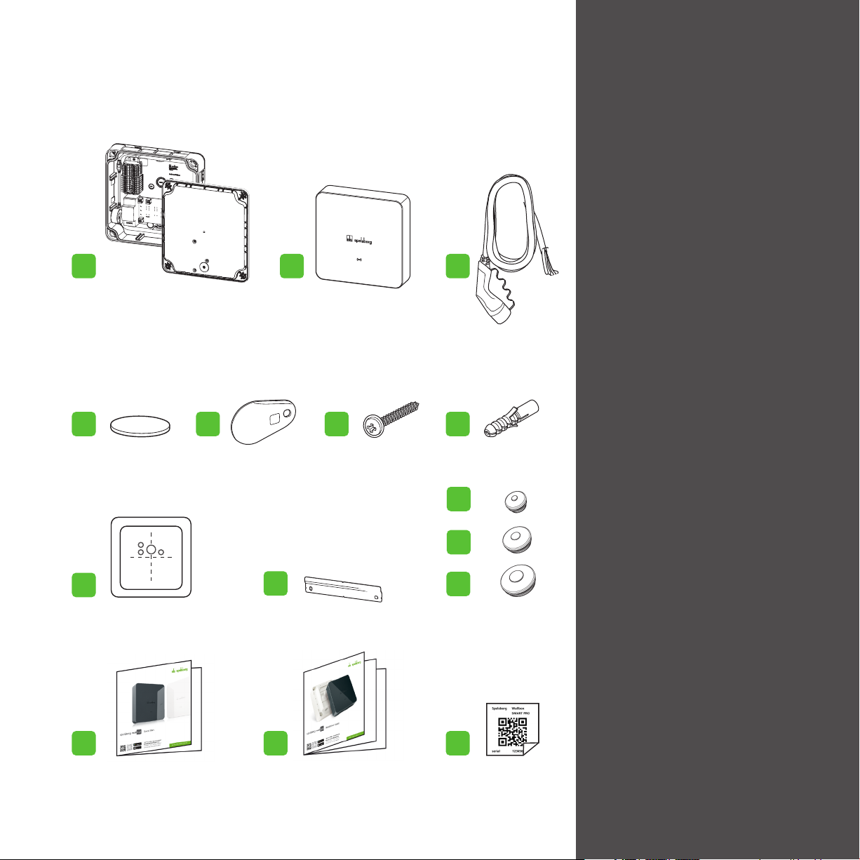
Lieferumfang
Scope of delivery
spelsberg
w
allbox
1 x 1 x
5 x 3 x 4 x 4 x
1 x
3 x
1 x
1 x
1 x 1 x 3 x
1 x
1 x
Allgemeine Sicherheitshinweise 4
General safety 6
Zielgruppe 8
Target group 8
Bestimmungsgemäßer Gebrauch 9
Intended Use 9
Technische Beschreibung 10
Technical description 10
Bedienelemente + Anschlüsse 11
Controls + Connections 11
Vorraussetzungen 12
Prerequisites 12
Vorbereitung für die Installation 13
Preparation for installation 13
Steckverbinderbelegung überprüfen 14
Checking the connector configuration 14
Installation bei Wandmontage 15
Installation for wall mounting 15
Anschluss des Ladekabels 18
Connecting the charging cable 18
Anschluss der Spannungsversorgung 19
Connecring the power supply 19
Anschluss der Leitungen 22
Connecting lines 22
Notwendige Prüfungen + Messungen 23
Necessary tests and measurements 23
Erstinbetriebnahme 24
Initial commissioning 24
Einrichtung durch den Installateur 25
Setup by installer 25
Konfiguration der Wallbox 26
Configuration of the Wallbox 26
Ersteinrichtung durch den Benutzer 27
Set up by user 27
Status LED + Summer 28
Status LED + buzzer 28
Fehlerbehebung 29
Troubleshooting 29
Elektrofahrzeuge laden 30
Charging an electric vehicle 30
Reparatur + Ersatzteile + Updates 32
Repair + Spare parts + Updates 32
Deinstallation / Deinstallation 33

4
Vorsicht Verletzungsgefahr
Der Benutzer kann durch beschädigte
Komponenten verletzt werden.
Montieren Sie die Ladestation nicht
- in der Nähe brennbarer Materialien.
- in explosionsgefährdeten Bereichen.
- in salzhaltiger oder nasser Umgebung.
- in der Nähe von aggressiven Dämpfen.
- in Umgebungen, die permanenter Vibration
ausgesetzt sind.
Zu Umgebungen dieser Art zählen z. B.
Außenbereiche von Tankstellen,
Chemiewerken, Mülldeponien, Klärwerken.
Beschädigungsgefahr durch
Witterungseinflüsse
Die Ladestation kann durch falsche
Standortwahl beschädigt werden.
- Setzen Sie die Ladestation keiner Wärmequelle
aus (z. B. direkte Sonneneinstrahlung, Heizung).
- Montieren Sie die Ladestation an einem
Platz, der gegen Regen und Spritzwasser
geschützt ist (zum Beispiel im geschützten
Außenbereich).
- Betreiben Sie die Wallbox nicht bei
Außentemperaturen unter –25 °C
oder über +40 °C.
Allgemeine Sicherheit
Lebensgefahr durch Stromschlag
- Wenn die Wallbox oder die angeschlossenen
Kabel sichtbare Beschädigungen aufweisen,
nehmen Sie die Wallbox außer Betrieb.
- Wenn angeschlossene Kabel und Leitungen
der Wallbox beschädigt werden, lassen Sie
diese durch einen qualifizierten Fachbetrieb
ersetzen, um Gefährdungen zu vermeiden.
- Ziehen Sie das Ladekabel immer an der
Kupplung aus dem Fahrzeug-Inlet oder
dem optionalen
Steckerhalter aus dem
Zubehör, niemals am Kabel.
- Tauchen Sie die Fahrzeug-Ladekupplung
niemals in Flüssigkeiten.
Gesundheitsgefahr
- Im Falle von Feuer lösen Sie nicht den
Deckel der Wallbox. Verwenden Sie für
elektronische Geräte zugelassene Löschmittel.
Verwenden Sie kein Wasser zum Löschen.
- Dieses Gerät kann von Personen mit
eingeschränkten physischen, sensorischen
oder geistigen Fähigkeiten oder einem
Mangel
an Erfahrung und Wissen verwendet
werden, wenn sie beaufsichtigt werden oder
eine Anleitung zur sicheren Benutzung des
Geräts erhalten haben und sie die daraus
resultierenden Gefahren verstehen.
- Kinder dürfen nicht mit dem Gerät spielen.
- Reinigung und Benutzer-Wartung dürfen
nicht von Kindern durchgeführt werden.
Beschädigungsgefahr durch Bohrungen
Teile der Installation können durch unsach-
gemäße Bohrungen beschädigt werden.
- Bevor Sie Bohrungen an der Wand/Montage
fläche vornehmen, stellen Sie sicher, dass
keine elektrischen Kabel oder andere
Leitungen durch das Bohren beschädigt werden.
Gefahr von Tod, schweren
Verletzungen und Verbrennungen
Gefährliche Lichtbögen können zum Tod
oder schweren Verletzungen führen.
- Ziehen Sie die Fahrzeug-Ladekupplung auf
keinen Fall mit Gewalt. Je nach
Elektrofahrzeug kann die Abschaltung
des Ladevorgangs und die Dauer der
Entriegelung variieren.
Ein unsachgemäßer Umgang mit dem
Ladekabel kann Stromschläge und
Kurzschlüsse verursachen.
- Beachten Sie die allgemein gültigen
Sicherheitsvorkehrungen und die folgenden
Hinweise.
- Prüfen Sie vor jeder Benutzung das
Ladekabel und die Kontakte auf Schäden
und Verschmutzung.
- Laden Sie niemals mit einem beschädigten
Ladekabel oder Fahrzeug-Inlet.
- Laden Sie niemals mit Ladekupplungen,
die verschmutzt oder feucht geworden sind.
- Schließen Sie das Ladekabel nur an Fahr-
zeug-Inlets an, die vor Wasser, Feuchtigkeit
und anderen Flüssigkeiten geschützt sind.
Hinweis: Die Spelsberg Wallbox muss
beim Netzbetreiber angemeldet werden.

5
Sachschaden durch fehlende
Verschlussstopfen
- Werden die Kabeleinführungen im Gehäuse
nicht oder nur unsachgemäß mit den
mitgeliferten Doppelmembranstutzen (DMS)
abgedeckt, ist die angegebene
Schutzart nicht mehr gewährleistet.
Es kann zu Folgeschäden an
den Elektronikkomponenten kommen.
» Leitungseinführungen im Gehäuse
mit mitgelieferten DMS abdecken.
- Es gibt Elektrofahrzeuge, die ein Starten des
Fahrzeugs mit gestecktem Ladekabel
erlauben. Achten Sie immer darauf, das
Ladekabel vor dem Losfahren zu lösen.
- Verwenden Sie das Ladekabel nicht mit einem
Verlängerungskabel oder einem Adapter.
- Falls die Steckverbindung raucht oder
schmilzt, fassen Sie niemals das Ladekabel an.
Wenn möglich, brechen Sie den Ladevorgang ab.
- Achten Sie darauf, dass das Ladekabel für
Kinder nicht zugänglich ist.
- Lasten und Stöße vermeiden .
- Ladekabel nicht über scharfe Kanten ziehen.
- Ladekabel nicht verknoten, Knicke vermeiden.
- Ladekabel beim Laden vollständig abwickeln.
- Ladekabel nicht unter Zugspannung setzen.
Die Ladekupplung kann durch
Umwelteinflüsse beschädigt werden.
- Wenn die Fahrzeug-Ladekupplung nicht
benutzt wird, stecken Sie immer die
Schutzkappe auf.
- Alternativ können Sie die Fahrzeug-Lade-
kupplung in einen optionalen Steckerhalter
aus dem Zubehör stecken.
Lagerung
- Bewahren Sie das Gerät sowie das Ladekabel
und das Zubehör vor der Montage an einem
trockenen und sauberen Ort auf.
- Bitte lagern Sie die Wallbox in ihrem
Originalkarton.
Reinigung
Beim Arbeiten an den elektrischen
Komponenten der Wallbox besteht die
Gefahr eines elektrischen Schlags.
- Reinigen Sie das Ladekabel nur, wenn es
nicht am Fahrzeug angeschlossen ist.
- Reinigen Sie die Wallbox und das
Ladekabel nur äußerlich.
Falsche Reinigungsmittel können
die Wallbox beschädigen
- Verwenden Sie keine scharfen oder harten
Mittel zur Reinigung.
- Verwenden Sie kein Wasser und
keinen Dampfstrahlreiniger.
- Reinigen Sie das Designcover und das Lade-
kabel mit einem weichen, trockenen Tuch.
- Bei Bedarf: Reinigen Sie das Designcover mit
einem weichen, feuchten Tuch. Hartnäckige
Verschmutzungen können mit einem milden,
lösungsmittelfreien, nicht scheuernden
Reinigungsmittel entfernt werden.
Transport
Sachschaden durch unsachgemäßen
Transport.
- Kollisionen und Stöße vermeiden.
- Produkt bis zum Aufstellort eingepackt
transportieren.
- Achten Sie darauf, dass das
Verpackungssiegel unbeschädigt ist.
- Achten Sie darauf, dass die Ädhäsionsfolie
auf dem Designcover unbeschädigt ist.
Ziehen Sie diese erst ab, wenn das
Designcover montiert ist.

6
General safety
Risk of fatal electric shock
- If the wallbox or the connected cables are
visibly damaged, take the wallbox out of
operation.
- If the connected cables and lines of the wallbox
are damaged, have them replaced by a
qualified specialist company to avoid hazards.
- Always pull the charging cable from the
vehicle inlet by the plug or by the optional
plug holder accessory, never by the cable.
- Never immerse the vehicle charging
plug in liquids.
Health hazard
- Do not unfasten the cover of the wallbox
in the event of a fire. Use extinguishing
agents approved for electronic devices.
Do not use water for extinguishing.
- This device can be used by persons
with reduced physical, sensory or mental
capabilities or lack of experience and
knowledge, provided that they are
supervised or have been instructed on
using the device safely and they
understand the hazards involved.
- Children must not be allowed to play
with the device.
- Cleaning and operator maintenance must
not be performed by children.
Risk of damage from drilling
Damage can be caused by badly
executed drilling.
- Before drilling holes in the wall or
mounting surface, make sure that this
will not damage any electrical cables or
other lines.
Risk of death, serious injury and burns
Dangerous arcing can cause death or
serious injury.
- Never pull the vehicle charging plug
out by force. Depending on the
electric vehicle, the ending of the
charging process and the time it takes
to unlock may vary.
Incorrect handling of the charging cable
can cause explosions, electric shocks and
short circuits. Observe the generally
applicable safety precautions and the
following instructions.
- Before each use, check the charging cable
and the contacts for damage and dirt.
- Never use a damaged charging cable
or vehicle inlet.
- Never charge with contacts that are dirty or damp.
- Only connect the charging cable to
vehicle inlets that are protected from water,
moisture and other liquids.
- There are electric vehicles that can be
started with the charging cable plugged in.
- Always be sure to disconnect the charging
cable before driving off.
- Do not use the charging cable with an
extension lead or adapter.
Note: In Germany the wallbox must be
registered at the local grid operator.
Risk of injury
Users can be injured by damaged
components.
Do not install the charging station:
- Near flammable materials.
- In areas with explosion hazards.
- In salty or wet environments.
- In the vicinity of aggressive vapours.
- In environments subject to constant
vibration.
Examples of these environments of include
petrol station forecourts, chemical plants,
waste disposal sites and sewage plants.
Risk of damage due to
weather conditions
Incorrect choice of location can
damage the charging station.
- Do not expose the charging station to
any heat sources (e.g. direct sunlight
or heaters).
- Install the charging station in a location
protected from rain and splashing water
(for example, in a sheltered outdoor area).
- Do not operate the wallbox at outside
temperatures below -25 °C or above +40 °C.

7
Property damage due to
missing sealing plug
- Will the cable entries in the case not or only
insufficiently with the supplied sealing (DMS)
plug covered, the specified protection class
is no longer guaranteed. There may be
consequential damage to the electronic
components.
» Cover the cable entries in the
enclosure with supplied DMS.
- Never touch the charging cable if the
connector is smoking or has melted.
Stop the charging process if possible.
- Make sure that the charging cable is out
of the reach of children.
- Avoid loads and impacts.
- Do not pull the charging cable over sharp edges
- Do not knot the charging cable, avoid kinks.
- Completely unwind the charging
cable when charging.
- Do not put the charging cable under tension.
The charging plug can be damaged by
environmental influences.
- Always put the protective cap on the
vehicle charging plug when it is not in use.
- Alternatively, you can put the vehicle
charging plug into a plug holder,
which is available as an accessory.
Storage
- Keep the device and the charging cable
and the accessories before assembly
on a dry and clean place.
- Please store the charging station
in the original packaging.
Cleaning
There is a risk of electrocution when wor-
king on the electrical components of the
wallbox.
- Only clean the charging cable when it
is not connected to the vehicle.
- Only clean the outside of the wallbox
and the charging cable.
Unsuitable cleaning agents can
damage the wallbox.
- Do not use any sharp or hard
objects for cleaning.
- Do not use water or a steam jet cleaner.
- Clean the wallbox and the charging
cable with a soft, dry cloth.
- If necessary: Clean the wallbox with a soft,
damp cloth. Stubborn dirt can be removed
with a mild, solvent-free, non-abrasive
cleaning agent.
Transport
Material damage due to improper
transport.
- Avoid collisions and bumps.
- Product packed up to the place of
installation transport.
- Make sure, that the packaging seal
is undamaged.
- Make sure that the adhesive foil
on the design cover is undamaged.
Do not remove it until the
design cover is mounted.

8
Zielgruppe
Target group
Als Benutzer sind Sie für das Gerät verantwortlich.
Ihnen obliegt die Verantwortung für bestimmungs-
gemäße Verwendung und sicheren Gebrauch des
Geräts. Dazu zählt auch die Einweisung von Personen,
die das Gerät verwenden. Als Benutzer ohne elektro-
technische Fachausbildung dürfen Sie nur Tätigkeiten
durchführen, die keine Elektrofachkraft erfordern.
Als Elektrofachkraft verfügen Sie über eine aner-
kannte elektrotechnische Ausbildung. Aufgrund
dieser Fachkenntnisse sind Sie autorisiert, die in
dieser Anleitung geforderten elektrotechnischen
Arbeiten auszuführen.
Kenntnisse der Elektrofachkraft:
- Allgemeine und spezielle Sicherheits-
und Unfallverhütungsvorschriften.
- Elektrotechnische und nationale Vorschriften.
- Risiken-Erkennung und Gefahren-
Vermeidung.
Tätigkeiten nach Zielgruppe
Benutzer
- Bedienung
- Reinigung
- Störungsbeseitigung
- Benutzer Inbetriebnahme
Elektrofachkraft
- Installation
- Erstinbetriebnahme
- Außerbetriebnahme
As user, you are responsible for the device.
You are responsible for the intended proper and
safe use of the device. This also includes the
instruction of people who use the device.
As user without specialist electrical training,
you may only carry out activities that do not
require an electrician.
As a qualified electrician, you have a recognized
electrical engineering training. Based on this
specialist knowledge, you are authorized to carry
out the electrical work required in these instructions.
Knowledge of the electrician:
- General and special security
and accident prevention regulations.
- Electrical and national regulations.
- Risk identification and danger avoidance.
Tasks according to group
User
- Operation
- Cleaning
- Troubleshooting
- User Setup
Qualified electrician
- Installation
- Initial commissioning
- Decommissioning

9
Die Wallbox ist zum Laden von Elektrofahrzeugen
mit einer Typ-2-Kupplung durch Wechselspannung
bestimmt. Sie ist fest an das Wechselspannungs-
netz angeschlossen. Sie ist für eine Innen- und
Freiluftnutzung geeignet und für die Wand- und
Stelenbefestigung vorgesehen.
Es dürfen nur die von Spelsberg vorgesehenen
Stelen zur Stelenbefestigung verwendet werden.
Die Wallbox muss nach den internationalen und
nationalen geltenden Vorschriften betrieben werden.
Zu beachten sind folgende internationale Vor-
schriften bzw. jeweilige nationale Umsetzungen:
- IEC 61851-1
- IEC 62196-1
- IEC 60364-7-722
- IEC 61439-7
Die Wallbox kann in Bereichen mit uneingeschränk-
tem Zugang verwendet werden. Sie ist nur für den
privaten Einsatz bestimmt. Jede andere Verwendung
ist nicht bestimmungsgemäß.
Der Benutzer ist jederzeit für den ordnungsgemäßen
und sicheren Zustand der Wallbox verantwortlich
und muss diese in regelmäßigen Abständen über-
prüfen. Der Hersteller haftet nicht für
Sach- oder Personenschäden, die aus
unsachgemäßer Verwendung erfolgen, z. B.:
- Montage- oder Anschlussfehler.
- Beschädigungen am Produkt durch mechani-
sche Einflüsse und falsche Anschlussspannung.
- Veränderungen am Produkt ohne
ausdrückliche Genehmigung vom Hersteller.
- Verwendung für andere als die in der
Anleitung beschriebenen Zwecke.
The wallbox is designed for charging electric
vehicles with a type 2 connection using
alternating current. The wallbox is permanently
connected to the AC mains. The wallbox is
suitable for indoor and outdoor use and is
intended for mounting on a wall or pedestal.
Only pedestals provided by Spelsberg may be
used for mounting. The wallbox must be
operated in accordance with the applicable
international and national regulations.
The following international regulations and
national implementations must be observed:
- IEC 61851-1
- IEC 62196-1
- IEC 60364-7-722
- IEC 61439-7
The wallbox can be used in areas with
unrestricted access. It is intended for private
use only. Any other use is inappropriate.
The user is responsible for ensuring that the wall-
box is always kept in a proper and safe
condition and must check it at regular intervals
The manufacturer is not liable for property
damage and personal injury resulting from
improper use, e.g.:
- Assembly or connection errors.
- Damage to the product due to mechanical
effects and incorrect connection voltage.
- Modifications to the product without
the express permission of the manufacturer.
- Use for purposes other than those
described in the manual.
Bestimmungsgemäßer Gebrauch
Intended Use

10
Weitere Informationen entnehmen Sie bitte
unserem online verfügbaren Produkthandbuch
unter: www.spelsberg.de/support/wallbox
For more information, please refer to
our online product manual:
www.spelsberg.com/support/wallbox
Technische Beschreibung
Technical description
Die Wallbox stellt die Wechselspannung
zum ein- oder dreiphasigen Laden von
Elektrofahrzeugen bereit (Ladebetriebsart 3,
Anschlussfall C nach IEC 61851).
Sobald das Ladekabel mit dem Elektrofahrzeug
verbunden ist, kann der Ladevorgang beginnen.
Hinweis: Die Funktion zur Belüftung
(Zustand D) wird nicht unterstützt.
Je nach Einstellung in der Wallbox muss der
Ladevorgang erst durch den Benutzer autorisiert
werden, bevor der Ladevorgang gestartet wird.
Das fest angeschlossene Ladekabel kann nach
dem Ladevorgang an der Wallbox aufgewickelt
werden. Die Schutzkappe verhindert das
Eindringen von Feuchtigkeit in die Ladekupplung.
Eine Status-LED und ein Summer
signalisieren die Zustände der Wallbox
und des Ladevorgangs.
Die Wallbox schaltet die Spannung bei
folgenden Umgebungsbedingungen ab:
- Gleichfehlerströme > 6 mA
- Zu hohe Temperatur
- Überlast (nur Smart Pro)
- Überspannung /
Unterspannung (nur Smart Pro)
Die Wallbox Smart Pro kann durch
folgende Optionen mit dem Internet
verbunden werden:
- LAN (Standard)
- WLAN
The wallbox provides the AC voltage for
single-phase or three-phase charging of
electric vehicles (charging mode 3,
connection case C according to IEC 61851).
As soon as the charging cable is connected to the
electric vehicle, the charging process can begin.
Note: Feature for ventilation
(State D) is not supported.
Depending on the setting in the wallbox,
charging may have to be authorised by the user
before it begins. After charging, the permanently
connected charging cable can be stored using
the cable manager of the wallbox. The protective
cap prevents moisture from entering the charging
plug. A status LED and a buzzer signal the states
of the wallbox and the charging process.
The wallbox switches off the voltage in
the following situations:
- DC fault currents above 6 mA
- Excessive temperature
- Overload (Smart Pro only)
- Overvoltage /
undervoltage (Smart Pro only).
The Smart Pro wallbox can be
connected to the internet using
the following options:
- LAN (Standard)
- Wifi
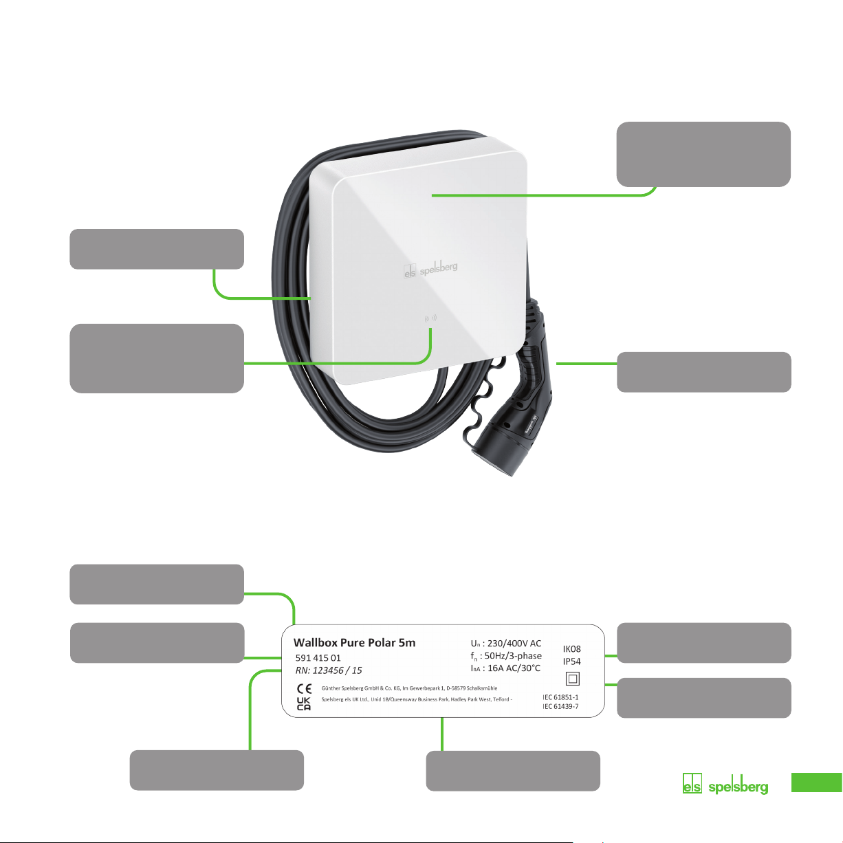
11
Ladekupplung Typ 2/
Connector type 2
Typenschild / Type label
(unter Designcover /
below the design cover)
Status-LED,
Summer, RFID-Leser /
Status-LED,
buzzer, RFID reader
Kabelaufbewahrung/
Cable management
Bedienelemente + Anschlüsse
Controls + Connections
Technische Daten/
Technical data
Schutzklasse/
Protection class
Artikelnummer/
Order number
Seriennummer/
Serial number
Bezeichnung/
Decription
Hersteller-Adresse/
Manufactor adress
Typenschild
Type label

12
Die folgenden Schutzeinrichtungen
müssen bauseits zur Absicherung der
Wallbox vorgesehen werden:
Vorsicherung mit max. 16 A.
- 230 V: LS-Schalter (C-Charakteristik); 1-polig
- 400 V: LS-Schalter (C-Charakteristik); 3-polig,
allpolig schaltend
Fehlerstrom-Schutzeinrichtung
RCD Typ A mit IΔn ≤30 mA
- 230 V: FI-Schutzschalter 2-polig
- 400 V: FI-Schutzschalter 4-polig
Je nach Installationsort:
Überspannungsschutzeinrichtung nach
nationalen und regionalen Vorschriften
Beachten Sie bei der Wahl des
Montageorts folgende Hinweise:
- Montieren Sie die Wallbox nur vertikal
(z. B. an Gebäudewänden).
- Die Montagefläche muss eben sein und
eine ausreichende Festigkeit aufweisen.
Bei Unebenheiten auf der Wand von
mehr als 2 mm ist ein Ausgleich unter
d
en Befestigungspunkten notwendig, um ein
Verziehen des Gehäuses zu vermeiden.
- Das verwendete Befestigungsmaterial muss
für die Befestigungsfläche geeignet sein.
Voraussetzungen
Requirements
- Der freie Abstand um die Wallbox muss
mindestens 250 mm betragen. Dies gilt auch
für Bewuchs durch Pflanzen.
- Achten Sie auf ausreichend Abstand zu
anderen Hindernissen in der Montageumge-
bung. Die Unterkante der Wallbox muss sich
mindestens 900 mm über dem Boden befinden.
- Die Wallbox muss während des Betriebs
immer ausreichend beleuchtet sein.
Installieren Sie gegebenenfalls eine
Beleuchtung.
The following equipment must be
provided on site to protect the wallbox:
Pre-fuse with a maximum rating of 16 A.
- 230 V: Miniature circuit breaker
(C characteristic); 1-pole
- 400 V: Miniature circuit breaker
(C characteristic); 3-pole, all-pole switching
Residual current device RCD Type A
with IΔn ≤30 mA
- 230 V: Residual current circuit breaker,
2-pole
- 400 V: Residual current circuit breaker,
4-pole
Depending on the installation location:
Overvoltage protection device according to
national and regional regulations.
Observe the following when choosing
the installation location:
- Always mount the wallbox upright
(e.g. on building walls).
- The mounting surface must be level and
sufficiently strong. If there is unevenness on
the wall of more than 2 mm, compensation
is required under the mounting points to
prevent the enclosures from warping.
- The fastening material used must be
suitable for the mounting surface.
- There must be at least 250 mm free
space around the wallbox. This includes
plant growth.
- Make sure to keep a sufficient distance
to other obstacles in the installation area.
- The bottom of the wallbox must be at least
900 mm above the ground.
- The wallbox must always be sufficiently lit
during operation. Install lighting if necessary.

13
Wenn der Durchmesser der Versorgungs-
leitung den Dichtbereich des vorinstallierten
DMS M25 überschreitet:
- Entfernen Sie den entsprechenden
DMS M25.
- Brechen Sie die entsprechende
Vorprägung aus.
- Montieren Sie einen DMS M32.
Nur bei Leitungseinführung durch die
Rückwand: Schrauben Sie den
Gehäusedeckel von der Wallbox ab.
Hinweis: Die Vorprägung für das
Ladekabel ist mit einem DMS versehen
(unten rechts an der Wallbox). Für die
Spannungsversorgung sind DMS an der Ober-
und Unterseite der Wallbox vormontiert.
Das Ausbrechen einer Vorprägung ist nur erfor-
derlich, wenn weitere Leitungen angeschlossen
werden sollen, oder die Versorgungsleitung von
der Rückseite in die Wallbox eingeführt werden soll.
- Brechen Sie die benötigten Vorprägungen
aus dem Gehäuse aus.
- Montieren Sie die jeweiligen DMS.
Vorbereitung der Installation
Preparation for installation
Only for cable entry through the back wall:
Unscrew the enclosure cover from the
wallbox.
Note: The knockout for the charging
cable has a DMS (bottom right of the
wallbox). For the power supply, there are double
mechanical seals on the top and bottom of the
wallbox preassembled. Knockouts only have to be
opened if additional cables are to be connected
or the supply cable is to be fed into the wallbox
from the rear.
- Open the required knockouts
from the enclosure.
- Fit the appropriate double
membrane seals.
If the diameter of the supply cable is too
big for the sealing area of the pre-installed
M25 DMS:
- Remove the M25 DMS.
- Open the appropriate knockout.
- Install an M32 DMS.
60 − 75°

14
Steckverbinderbelegung überprüfen
Checking the connector configuration
Anschluss LAN
(LAN-2, nur Smart Pro)
Connection for LAN
(LAN-2, Smart Pro only)
Anschluss LAN
(LAN-1, nur Smart Pro)
Connection for LAN
(LAN-1, Smart Pro only)
1x USB Typ A
(Anschluss HMI-Platine)
1x USB type A (HMI
board connection)
1x USB Typ B (Serviceport)
1x USB type B (service port)
Anschluss Messstromwandler
Connection for measuring current transformer
Anschluss 2-Phasen
Abschaltung
(nur Smart Pro)
Connection for
2-phase disconnection
(Smart Pro only)
Anschluss PV Freigabe-
kontakt (nur Smart Pro)
Connection for PV
enabling contact
(Smart Pro only)
Anschluss
Schützsteuerung
Connection for
contactor control
Anschluss Versorgungsspannung
Connection for supply voltage
Anschluss Stecker A (PE, CP, ...)
Connection for plug A (PE, CP, ...)
Prüfen Sie, ob alle Stecker fest sitzen.
Check that all connectors are firmly fitted.
Gesteckt
Plugged
Nicht gesteckt
Not plugged
1x USB Typ A
(Anschluss HMI-Platine)
1x USB type A (HMI
board connection)

15
Anschluss LAN
(LAN-2, nur Smart Pro)
Connection for LAN
(LAN-2, Smart Pro only)
1x USB Typ A
(Anschluss HMI-Platine)
1x USB type A (HMI
board connection)
Installation bei Wandmontage
Installation for wall mounting
Hinweis: Verwenden Sie die
im Lieferumfang enthaltenen Dübel
und Schrauben und nur an den
dafür vorgesehenen Stellen um die
Schutzklasse zu gewährleisten.
Je nach Untergrund müssen geeignete
Dübel verwendet werden.
Zur Befestigung der Wallbox benötigen Sie:
- 4 Schrauben
- 4 Dübel
- Montageschiene
- Bohrschablone
Nutzen Sie die im Lieferumfang enthaltene
Bohrschablone, um die Befestigungspunkte
anzuzeichnen.
Note: Use the included dowels and
screws only on the designated places
to ensure the protection class.
Depending on the ground suitable dowels
must be used.
To fasten the wallbox you will need:
- 4 screws
- 4 dowels
- Mounting rail
- Drilling template
Use the included drilling template
to mark the fastening points.
1x USB Typ A
(Anschluss HMI-Platine)
1x USB type A (HMI
board connection)
Bohrschablone
Drilling Template
M32
M16
M16
M16
TOP
M2-007-01
150 mm
5,91“
68 mm
2,68“
163 mm
6,42“
45 mm
1,77“
Achtung: Verkleinerte Ansicht.
Nicht zur Verwendung geeignet!
Attention: Smaller illustation.
Not suitable for use.

16
Abbildung 1
- Markieren Sie die Befestigungspunkte
mithilfe der Bohrschablone oder Montageschiene.
- Bohren Sie die Löcher für die Befestigungspunkte.
- Stecken Sie die Dübel in die Bohrungen.
- Schrauben Sie die Montageschiene an.
Abbildung 2 (nicht erforderlich bei
Nutzung der Bohrschablone)
- Setzen Sie die Wallbox mittig
auf die Montageschiene auf (1.).
- Zeichnen Sie die Befestigungspunkte
für die Wallbox an (2.).
Nur bei Leitungseinführung durch die Rückwand:
- Zeichnen Sie die Leitungseinführungen an.
- Nehmen Sie die Wallbox von der Montageschiene.
Figure 1
- Marking the fastening points for the mounting rail
by using the drilling template or mounting rail.
- Drill the holes for the attachment points.
- Insert the dowels into the holes.
- Schrauben Sie die Montageschiene an.
Figure 2 (not neccessary if using the drilling template)
- Centre the wallbox on the mounting rail.
- Mark the fastening points for the wallbox.
Only for cable entry through the back wall:
- Mark the cable entries.
- Take the wallbox off the mounting rail.
150 mm
Installation bei Wandmontage / Montageschiene
Installation for wall mounting / Mounting rail
1
1
2
1.
2.

17
Installation bei Wandmontage / Wallbox
Installation for wall mounting / Wallbox
Installation ohne Bohrschablone
- Bohren Sie die Löcher für die Befestigungspunkte.
und stecken die Dübel in die Bohrungen.
Nur bei Leitungseinführung durch die Rückwand:
- Verlegen Sie die erforderlichen Kabel
(z. B. Spannungsversorgung, LAN-Kabel).
- Schließen Sie zunächst das Ladekabel an
(s. „Anschluss des Ladekabels).
Nur bei Leitungseinführung durch die Rückwand:
- Führen Sie die erforderlichen Kabel durch die jeweiligen
Leitungseinführungen in der Rückwand der Wallbox.
- Setzen Sie die Wallbox mittig auf
die Montageschiene auf.
- Schrauben Sie die Wallbox mit den 2 Schrauben fest.
Installation ohne drilling template
- Drill the holes for the fastening points.
- Insert the wall plugs into the holes.
- Only for cable entry through the back wall:
Lay the required cables (e.g. power supply, LAN cable).
- Connect the charging cable
(see “Connecting the charging cable”).
Only for cable entry through the back wall:
- Push the required cables through the appropriate
cable entries in the back of the wallbox.
- Place the wallbox centrally on the mounting rail.
- Screw the wallbox tight with the 2 screws.
Installation mit Bohrschablone
- Schließen Sie zunächst das Ladekabel an
(s. „Anschluss des Ladekabels).
Nur bei Leitungseinführung durch die Rückwand:
- Führen Sie die erforderlichen Kabel durch die jeweiligen
Leitungseinführungen in der Rückwand der Wallbox.
- Setzen Sie die Wallbox mittig auf
die Montageschiene auf.
- Schrauben Sie die Wallbox mit den 2 Schrauben fest.
Installation with drilling template
- Connect the charging cable
(see “Connecting the charging cable”).
Only for cable entry through the back wall:
- Push the required cables through the appropriate
cable entries in the back of the wallbox.
- Place the wallbox centrally on the mounting rail.
- Screw the wallbox tight with the 2 screws.
18
Anschluss des Ladekabels
Connecting the charging cable
2.
PE
CP
N
L3
L2
L1
1.
>1 cm
3.
4.
Ladekabel anschließen
- Lösen Sie die Zugentlastung.
- Führen Sie das Ladekabel durch den
rechten unteren DMS M25 und
die Zugentlastungsschelle.
- Ziehen Sie das Ladekabel leicht zurück, sodass
der DMS einen Trichter nach unten bildet.
Der Mantel des Kabels muss noch mindestens
1 cm aus der Zugentlastung herausragen.
- Ziehen Sie die Zugentlastung fest
(Anzugsdrehmoment: 0,9 Nm).
- Stellen Sie sicher, dass sich das Ladekabel
nicht aus der Zugentlastung herausziehen lässt.
- Schließen Sie das Ladekabel an.
Connecting the charging cable
- Unfasten the strain relief.
- Feed the charging cable through the
bottom right M25 DMS and the
strain relief clamp.
- Pull the charging cable back slightly so
that the DMS forms a downward funnel.
The sheath of the cable must still protrude
at least 1 cm from the strain relief.
- Tighten the strain relief
(tightening torque: 0.9 Nm).
- Make sure that the charging cable
cannot be pulled out of the strain relief.
- Connect the charging cable.

19
Anschluss der Spannungsversorgung
Connecting the power supply
Warnung:
Lebensgefahr durch Stromschlag
Durch Fehler beim Anschluss an die
elektrische Spannungsversorgung besteht
die Gefahr eines elektrischen Schlags.
- Lassen Sie die Spannungsversorung
nur von einer zugelassenen Elektrofachkraft
ausführen.
- Installieren Sie einen geeigneten Fehlerstrom-
schutzschalter und eine geeignete Leitungs-
absicherung in der Zuleitung.
- Beachten Sie vor jeder Arbeit an
elektrischen Komponenten folgende
Sicherheitsregeln:
- Freischalten
- Gegen Wiedereinschalten sichern
- Spannungsfreiheit allpolig feststellen
- Erden und kurzschließen
- Benachbarte, unter Spannung stehende
Teile abdecken oder abschranken
- Beachten Sie die nationalen VDE-Vorschriften
und Gesetze.
- Achten Sie vor dem Anschluss darauf, dass
Zuleitung, Kupplung und Anschlussbuchsen
sauber und trocken sind.
- Berühren Sie nie die Kupplung, wenn Sie
nasse Hände haben oder mit den Füßen in
der Nässe stehen.
- Stellen Sie beim Anschließen der Zuleitung
und des LAN-Kabels sicher, dass die Kabel
und Leitungen nicht beschädigt werden.
- Achten Sie darauf, dass alle Kabeleinführun-
gen mit den beigelegten Doppelmembran-
stutzen verschlossen werden.
Warning:
Risk of electric shock
There is a risk of electrocution if
the electrical supply cable is not
properly connected.
- Always have the electrical supply
cable connected by a locally
authorised electrician.
- Install a suitable residual current
circuit breaker and line fuse in
the supply line.
- Observe the following safety rules
before any work on electrical
components:
- Disconnect the power supply
- Secure it against being switched on again
- Check that all poles are de-energised
- Earth and short-circuit
- Cover or enclose adjacent live parts
- Observe the local regulations and laws
- Before connecting, make sure that the
supply line, plugs and connection sockets
are clean and dry.
- Never touch the plugs if your hands are wet
or you are standing in water.
- Take care not to damage the cables and lines
when connecting the supply line
and LAN cable.
- Make sure, that all cable entries are closed
with the enclosed double membrane seals.
Weitere Informationen entnehmen Sie bitte
unserem online verfügbaren Produkthandbuch
unter:
www.spelsberg.de/support/wallbox
For more information, please refer to
our online product manual:
www.spelsberg.com/support/wallbox

20
2.
3.
1.
Anschluss der Spannungsversorgung
Connecting the power supply
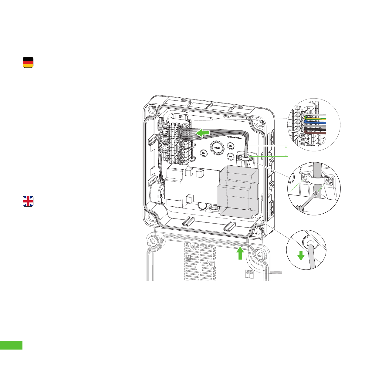
Spannungsversorgung anschließen
- Verwenden Sie eine Versorgungsleitung mit
einem maximalen Qerschnitt der Anschluss-
klemme: starr und flexibel 6 mm2,
flexibel mit AEH 4 mm2.
Connecting the power supply
- Use a supply cable with a maximum
cross-section of the connection terminal:
rigid and flexible 6 mm²,
flexible with 4 mm² ferrule.
This manual suits for next models
3
Table of contents
Popular Enclosure manuals by other brands


SilverStone
SilverStone GD03 manual

Icy Box
Icy Box IB-382H-C31 manual

Sarotech
Sarotech NAS-20 Quick installation guide

ZyXEL Communications
ZyXEL Communications NSA221 quick start guide

Middle Atlantic Products
Middle Atlantic Products Cablesafe CWR Series instruction sheet

Manhattan
Manhattan 700504 Specifications


