Seagate Exos E 4U106 Product manual

Exos® E 4U106 Hardware
Installation and Maintenance Guide
Abstract
This guide describes initial hardware setup for Seagate Exos 4U106 controller enclosures and disk enclosures. It also
describes removal and installation of customer-replaceable components. The guide is intended for use by storage
system administrators familiar with servers and computer networks, network administration, storage system
administration and configurations, storage area network management, and relevant protocols.
Part Number: 83-00007495-02-01
Revision: B
Published: December 2021

© 2021 Seagate Technology LLC or its affiliates. All rights reserved. Seagate, Seagate Technology, and the Spiral logo are registered trademarks of Seagate Technology LLC in
the United States and/or other countries. Exos is either a trademark or registered trademark of Seagate Technology LLC or one of its affiliated companies in the United States
and/or other countries. All other trademarks or registered trademarks are the property of their respective owners. All coded instruction and program statements contained
herein remain copyrighted works and confidential proprietary and trade secret information of Seagate Technology LLC or its affiliates. Any use, derivation, disassembly, reverse
engineering, dissemination, reproduction, or any attempt to modify, prepare derivative works, reproduce, distribute, disclose copyrighted material of Seagate Technology LLC,
for any reason, in any manner, medium, or form, in whole or in part, if not expressly authorized, is strictly prohibited. Seagate reserves the right to change, without notice, product
offerings or specifications.
Open Source Third Party Licenses and Code
Seagate storage products use open source software components. To view information about open source software licenses and open source code used in Seagate storage
products, see www.seagate.com/support.

Contents 3
Contents
1 Introduction 8
Intended audience 8
Knowledge prerequisites 8
Product documentation and support 8
Safety guidelines 8
2 System overview 9
Storage enclosure components 9
Storage enclosure chassis 9
Storage enclosure modules 10
Storage enclosure PCBAs 11
Optional components 12
3 Initial installation 13
Installation checklist 13
Complete installation prerequisites 14
Unpack and prepare the storage enclosure 15
Install the rackmount rail kit 17
Separate the inner rails from the outer and mid rails 18
Adjust the outer rails to the rack cabinet 21
Install the outer rails in the rack cabinet 24
Attach the inner rails to the storage enclosure 27
Install the storage enclosure 29
Mount the storage enclosure into the rack cabinet 29
Install the CMA and crossbar 32
Install drive carriers in the storage enclosure 36
Test enclosure connections 39
Route power cords and data cables 39
Route power cords from the power supply units 40
Route data cables from the controller module 42
Route enclosure and expansion data cables 45
Route and connect power cords and data cables 47
4 Operation 49
Apply power to the storage enclosure 49
Interpret system LEDs 50
Interpret front panel LEDs 50
Interpret input/output module LEDs 51
Storage enclosure management 52
Command-line interface usage 53
Storage Management Console usage 57
Update firmware 59
5 Hardware installation and configuration issues 60
Address initial start-up issues 60
Interpret FRU fault condition LEDs 61
Drive module fault LED 61
SAS expander module fault LED 61
Controller fan module fault LED 61
System fan module fault LED 62
Power supply unit status LED 63
Input/output module fault LEDs 64
Identify fault conditions 65
Isolate hardware and connectivity faults 66
Isolate system application faults 67
Take corrective action 68

6 In-service field maintenance 71
Replace a drive carrier 72
Replace a SAS expander module 74
Replace a controller fan module 75
Replace a system fan module 77
Replace a power supply unit 78
Replace an input/output module 80
Replace a main bay cover 83
Replace an auxiliary bay cover 85
A Technical specifications 87
B Standards and regulations 89
International standards 89
Potential for radio frequency interference 89
WEEE recycling 89
Index 90
4Contents

Contents 5
Figures
Figure 1 Storage enclosure with rails 10
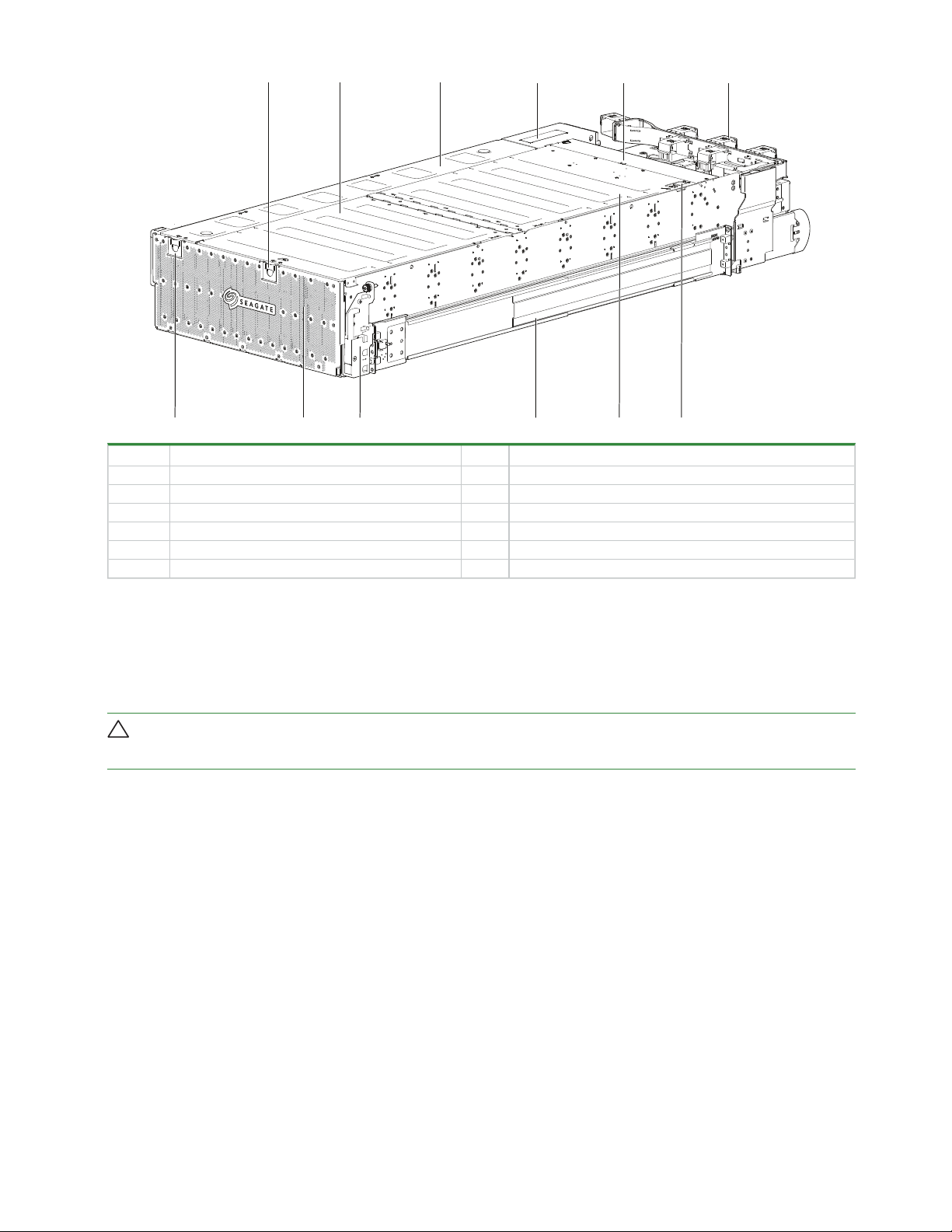
Figure 2 Customer-replaceable FRUs, top view 11
Figure 3 Storage enclosure PCBAs 12
Figure 4 Default belt straps already around the storage enclosure 16
Figure 5 Optional lift handles attached to the storage enclosure 16
Figure 6 Left and right lift handles 17
Figure 7 Separated left rail assembly, inner sides facing 19
Figure 8 Extension of left inner rail beyond mid rail 20
Figure 9 Location of inner rail safety lock 20
Figure 10 Location of mid rail release switch lever 21
Figure 11 Distance measurement of rack inside post-to-post depth 22
Figure 12 Default location of outer rail adjustment setscrews 22
Figure 13 Measurement of rail from rear to front mount bracket 23
Figure 14 Sample adjusted distance for outer rail setscrews 23
Figure 15 Alignment of CMA B bracket to rear outer rail bracket holes alignment and attachment 24
Figure 16 Attach the rear of the outer right rail assembly 25
Figure 17 Right front post detail of the inserted outer right rail assembly 26
Figure 18 Location for cage nut near top of allocated 4U space 27
Figure 19 Left and right inner rail edge details 28
Figure 20 Left inner rail alignment to storage enclosure chassis 28
Figure 21 Lock of rail against T-pins, alignment of screw holes to chassis sidewall 28
Figure 22 Attachment of the CMA A bracket 29
Figure 23 Align inner rails with mid and outer rails, detail 30
Figure 24 Leaf spring latch engaged, extension of mid rail to fully forward and locked position 31
Figure 25 Release both safety lock latches 32
Figure 26 Attachment of the CMA bracket assembly to the CMA A bracket on the chassis 33
Figure 27 Insertion of CMA bracket assembly into CMA B bracket on the outer rail 34
Figure 28 Proper installation of the CMA bracket assembly 34
Figure 29 Direction to tighten crossbar thumbscrews 35
Figure 30 Location for insertion of rack ear transport screws 35
Figure 31 Location for insertion of crossbar transport screws 36
Figure 32 Front half of unpopulated main bay 37
Figure 33 Orient drive carrier handle to rear 37
Figure 34 Required installation of first complete row of drive carriers 38
Figure 35 Rear half of unpopulated main bay 38
Figure 36 Auxiliary bay latch 39
Figure 37 Location of cable capture clip release screw 41
Figure 38 Power cord routing up to cable capture clip 41
Figure 39 Final power cord routing 42
Figure 40 Open cable capture arms on chassis 43
Figure 41 Proper order of data cables 43
Figure 42 Route for sample data cables on either side of the CMA cable capture arm 44
Figure 43 Sample HBA data and management connections 45
Figure 44 Sample reverse cabling method among host switches and expansion modules 46
Figure 45 Sample invalid loop (in red) among host switches and expansion modules 47
Figure 46 Close all CMA bracket clips 48
Figure 47 Route power cables to redundant PDUs 50
Figure 48 Front panel LEDs 51
Figure 49 Input/output module LEDs 52
Figure 50 Ports on sample controller module 53
Figure 51 Drive fault LED on top panel 61
Figure 52 SAS expander module LEDs, component side 61
Figure 53 Controller fan module fault LED, rotated orientation 62
Figure 54 System fan module fault LED 63

Figure 55 Power supply unit fault LED 64
Figure 56 Input/output module LEDs to examine for fault conditions 64
Figure 57 Removal of drive carrier from the main bay (other drive carriers removed for clarity) 73
Figure 58 Removal of a SAS expander module 75
Figure 59 Removal of a controller fan 76
Figure 60 Removal of a system fan 78
Figure 61 Removal of the PSU without power 79
Figure 62 Removed PSU 80
Figure 63 Input/output module LEDs to examine for fault conditions 81
Figure 64 Release of the input/output module latch handle 82
Figure 65 Access main bay cover's rear latch 83
Figure 66 Rear half of an unpopulated main bay 84
Figure 67 Main bay cover's front hinge pin 84
Figure 68 Access auxiliary bay cover's latch 85
6Contents

Contents 7
Tables
Table 1 Installation checklist tasks 13
Table 2 Fault LED prioritization 50
Table 3 Host port link LED status types 52
Table 4 Interface options 52
Table 5 Supported terminal emulator applications 54
Table 6 Terminal emulator serial port hex codes 54
Table 7 Sample Linux Minicom serial port parameter settings 54
Table 8 Terminal emulator port connection settings 55
Table 9 Factory default network port IP addresses 56
Table 10 Supported browsers 57
Table 11 Non-fault conditions 65
Table 12 Status of drive module or array, based on front panel Fault-Application LED 67
Table 13 Status of IOM , based on the green Cache LED and reboot 67
Table 14 Corrective action for fault conditions 68
Table 15 Time limits for FRU replacement 71
Table 16 Storage enclosure dimensions 87
Table 17 Storage enclosure FRU weights¹ 87
Table 18 Storage enclosure total weights 87
Table 19 Environmental specifications 87
Table 20 Power specifications 88
Table 21 Safety compliance 89

8Chapter 1 Introduction
1 Introduction
The Exos E 4U106 storage enclosure product is a high-capacity expansion enclosure designed for cloud and enterprise
environments, using ADAPT software features. It supports high-demand storage applications that require high data
availability, capacity, and performance. Each storage enclosure can be used either as a server-attached Just a Bunch of Disks
(JBOD), or cabled to a RAID bunch of disks (RBOD) as an Expanded Bunch of Disks (EBOD) for added storage. Each rail-
mounted storage enclosure fits within four (4) EIA rack space units in a 1.2 m rack. The integral cable management arm (CMA)
allows you to service individual, hot-swappable components within the storage enclosure, while retaining connection and
power.
Intended audience
This guide is for software integration providers, storage installation professionals, and system administration personnel.
Knowledge prerequisites
Make sure you have the appropriate knowledge base prior to product installation or service.
lServer system administration
lStorage system configuration
lStorage area network (SAN) management
lSerial Attached SCSI (SAS) protocol
lEthernet protocol
lRAID technology
Product documentation and support
To obtain the following documents, videos, and other product information, visit www.seagate.com/support.
Content description Document Seagate QR codes
Enhancements, known issues, and updates Release Notes
Documentation,
Support
Overview of product shipkit contents and setup support Getting Started*
Initial installation of hardware and component replacement Hardware Installation and Maintenance Guide
Regulatory compliance, safety, and disposal information Compliance, Safety, and Disposal Guide
* Printed document included in the shipkit.
Safety guidelines
You must adhere to all safety requirements in this document. Some relate to the entire system, some to the rack, some to the
storage enclosure, and others to the FRUs within it.

Chapter 2 System overview 9
2 System overview
The Exos 4U106 storage enclosure mounts to a rack cabinet, occupying four EIA rack space units (4U) and contains up to 106
hot-swappable drive modules.
CAUTION Make sure you are not connected to power at any time during installation procedures.
CAUTION Only operate the storage enclosure in a dust-free environment to meet temperature control and airflow
requirements.
Storage enclosure components
The typical 4U106 storage enclosure comes equipped with several core components.
lThe storage enclosure chassis exterior includes the front panel, top covers to access two internal bays, the rear panel, and
the rear crossbar.
lThe storage enclosure chassis interior contains baseplane, sideplane, and midplane PCBs and the remaining components
they control.
lThe main bay contains slots for 96 drive modules and an expander module for each of the eight (8) rows.
lThe auxiliary bay contains slots for 10 more drive modules, two (2) controller fan modules, and two (2) SAS personality
modules (PMs) interconnected with an inter-controller link (ICL) board.
lThe rear panel area contains four (4) system fan modules, two (2) power supply units (PSUs), and two (2) controller
modules (CMs).
lThe rackmount rail kit consists of two (2) rails that connect the storage enclosure to the rack cabinet.
lThe cable management arm (CMA) includes brackets on a flexible arm that routes and protects cables during in-rack
maintenance procedures.
Storage enclosure chassis
The storage enclosure sheet metal is bonded together and free from non-conductive coatings. The top and rear panels
provide access to plug-in drive modules, integrated PCBs, and other FRUs.
NOTE You can order and attach optional lift handles to storage enclosure sidewalls to position it onto the lift. You must
remove the lift handles after positioning the storage enclosure and prior to its installation into the rack. Lift handles are not
part of the standard package, so you must order and install them separately.

10Chapter 2 System overview
12
11
10
9
8
7
6
54
3
2
1
Item Description Item Description
1 Main bay cover front latch 7 Auxiliary bay cover latch
2Main bay front cover 8 Front panel
3Auxiliary bay cover 9 Pull handle
4 Fixed controller cover 10 Right rail assembly with CMA B bracket
5 Fixed midplane cover 11 Main bay rear cover
6 Cable management arm (CMA) 12 Main bay cover rear latch
Figure 1 Storage enclosure with rails
Storage enclosure modules
The storage enclosure contains a number of field-replaceable units (FRUs). Modules or components that require Seagate-
authorized warranty and repair personnel to replace them are not identified.
CAUTION If you partially populate the storage enclosure with disk drives, you must populate from front to back, filling
an entire lateral bay before populating the next bay.

Chapter 2 System overview 11
1
234
56
Item Description Function
1 Auxiliary bay drive module (10) Exchanges data on the controller channel
2 Controller fan module (2) Provides redundant cooling for auxiliary bay components
3 Controller module (2) Manages enclosure, fans, and LEDs; provides host connectivity
4 System fan module (4) Provides redundant cooling for main bay components
5 Main bay drive module (96) Exchanges data on the main bay channel
6 SAS expander module (8) Provides power and high-speed signal connection
N/A
Power supply unit (2) Provides redundant power to storage enclosure
Cable management arm (CMA) and hardware;
crossbar
Manages interconnection cables, providing full rail extension for service access;
provides stability
Rack rail (left and right) and hardware Provides support for a fully populated storage enclosure mounted within a rack
cabinet
Figure 2 Customer-replaceable FRUs, top view
Storage enclosure PCBAs
The storage enclosure provides separate access to two bays:the main bay and the auxiliary bay. The PCBAs identified in this
section are all assemblies that require replacement by Seagate-authorized warranty and repair personnel, other than the SAS
expander modules.

12Chapter 2 System overview
6
6
5
4
2
1
Item Description Function
1 Power midplane (1) Distributes power from the power supply units to each fan module and the main baseplane,
sends signals to the controller module, and provides busbar connection for both drive module
and controller channels
2 SAS riser sideplane (4) Passively balances drive module paths between both SAS expander modules, one per main
baseplane
3 SAS expander module (8),
customer-replaceable
Provides power and high-speed signal connection to the main baseplane via the riser
sideplanes, two per main baseplane
4 Fan baseplane (1) Distributes power to system fans and the controller baseplane
5 10-HDD baseplane (1) Provides power to the 10 auxiliary bay drive modules and signal connection to the dual
controller channel; does not support single-port drive modules
6 24-HDD baseplane (4) Provides power via a high-speed harness to each drive module on the 24-HDD baseplane and
signal connection to the dual drive channel; supports single-port drive modules
Figure 3 Storage enclosure PCBAs
Optional components
lOptional lift handles: The storage enclosure ships with three belt straps for lifting the enclosure to the mechanical lift.
You can also request optional lift handles to attach to the storage enclosure sidewalls. If you install lift handles to assist
you in positioning the enclosure on the lift, you must also remove them before you begin installation procedures.
lDrive carriers: In some situations, you can request optional drive carriers to surround a drive module for installation in a
drive carrier slot.

Chapter 3 Initial installation 13
3 Initial installation
Each storage enclosure installation requires the same amount of preparation to successfully mount it into your 1.2m industry-
standard rack cabinet.
WARNING! Heed all warnings and cautions on labeling and throughout this guide to reduce risk of personal injury or
damage to equipment.
CAUTION Use only power cords supplied in the installation kit or those that meet product specifications.
IMPORTANT Only a qualified service technician should perform the installation.
Installation checklist
Use this checklist, performing each task only in the sequence presented after successful completion of the prior step.
Step Task Reference
1 Complete all installation prerequisites. "Installation checklist" above;
"Complete installation prerequisites" on the next page
2 Unpack the storage enclosure. "Installation checklist" above;
"Unpack and prepare the storage enclosure" on page15
3 Prepare the site for installation of the storage enclosure
into the rack cabinet.
"Installation checklist" above;
"Unpack and prepare the storage enclosure" on page15
4 For rackmount installation, temporarily place all drive
modules in a static-protected area.
"Installation checklist" above
5 Install the rackmount kit in the rack cabinet. "Install the rackmount rail kit" on page17
6 Mount the storage enclosure into the rack cabinet. "Install the storage enclosure" on page29
7Install drive modules in the storage enclosure. "Install drive carriers in the storage enclosure" on page36
8 Connect all power cords and data cables. "Route power cords and data cables" on page39
9 Route storage enclosure cables to a compatible host. "Route and connect power cords and data cables " on page47
10 Test the enclosure to verify full functionality. "Test enclosure connections" on page39
11 Configure connection to management host. "Configure the management host for serial communication" on page53
Table 1 Installation checklist tasks
You must adhere to all related safety requirements prior to and during installation of a new storage enclosure and during FRU
replacement.
WARNING! Do not attempt to install the storage enclosure into the rack cabinet with drive modules preloaded in the
slots. Serious injury and damage could result. Unload any drive modules in storage enclosure slots to an static-protected area.
Do not further lighten the storage enclosure by removing other components.
CAUTION You must use a mechanical lift for mounting the storage enclosure into the rack cabinet. Do not use a vacuum
lift because it might damage the storage enclosure.

14Chapter 3 Initial installation
To adhere to installation safety precautions:
lSite preparation
1. Use the installation checklist.
2. Clear the site for installation and secure a static-protected area.
lBefore storage enclosure installation
1. Unpack the storage enclosure in a clear area, using appropriate safety precautions.
2. Temporarily set aside all drive modules into a static-protected area, regardless of how your storage enclosure or drive
modules ship.
3. Review all related warnings before mounting the storage enclosure into the rack.
lStorage enclosure installation
1. Use the provided belt straps or optional lift handles to move the storage enclosure onto a suitable mechanical lift.
2. Use a mechanical lift for positioning the storage enclosure and mounting it into the rack cabinet. Do not use a vacuum
lift. To maintain personal and equipment safety, do not use any other method to support the weight of the storage
enclosure during installation or maintenance.
3. Make sure the storage enclosure slides smoothly on its rails from full insertion to the service position. Do not force
insertion, which could damage the rails.
lBefore drive carrier installation
1. Prior to handling and replacing the drive modules, make sure you are static-compliant.
2. Make sure you can easily reach the slots in the enclosure safely while maintaining your balance.
lDrive carrier installation
1. Only after you securely mount the storage enclosure in the rack can you install the drive modules into the proper
module slots as part of the system setup.
2. (Optional) As an extra safety precaution, you may choose to continue supporting the weight of the storage enclosure
with the lift during drive module installation, then remove the lift when you are ready to fully insert the storage
enclosure into the rack cabinet.
CAUTION If you partially populate the storage enclosure with disk drives, you must populate from front to back, filling
an entire lateral bay before populating the next bay.
Complete installation prerequisites
The rackmount rails are designed to bear the maximum weight of the storage enclosure when it is properly mounted in a
standard rack cabinet. You can install multiple storage enclosures in a single rack cabinet.
CAUTION You must use only the supplied rail kit and related mounting hardware.
To complete installation prerequisites:
1. Prepare the host system for the installation by obtaining access to the following items:
a. A functioning host bus adapter
b. Known good cables for host connection that meet storage enclosure requirements
c. The provided right-angle power cords that meet power supply unit specifications

Chapter 3 Initial installation 15
2. Familiarize yourself with system configuration requirements and the layout of storage enclosure modules.
3. Obtain the following:
a. An anti-static wrist or ankle strap for handling static-sensitive components
b. A static-protected environment for temporary storage of the storage enclosure and the drive modules
c. A T10 screwdriver, 6-in length, and #2 Phillips-head magnetic screwdrivers, 6- and 12-in length
d. A retractable tape measure
e. A mechanical lift with sufficient clearance and capable of safely lifting the storage enclosure without drive modules
4. Ensure the rack cabinet is suitable for use with the storage enclosure.
a. A rack cabinet capable of holding 4U form factors, leveled in all planes with respect to each other
b. A maximum depth of 43.35 inches (1101mm) from back of front post to maximum extremity, excluding cabling and door
closure considerations
c. A rack cabinet that causes a maximum back air pressure of 5 pascals (0.5mm water gauge)
d. Weight capacity for the total number of storage enclosures installed, using a maximum of 310 lb (140kg) per storage
enclosure
NOTE Allocate and maintain a 1.7m or 5.58 ft safe distance to mount or remove a storage enclosure into a rack.
5. Secure sufficient staff to assist with the installation. Minimum staff:
a. One qualified service technician for the complete installation procedure
b. One spotter to assist with the lift and to observe the installation from the rear of the rack cabinet
c. A total of two to four people to unpack the storage enclosure and move it onto the mechanical lift
Unpack and prepare the storage enclosure
CAUTION Do not operate a storage enclosure outside the manufacturer's intended use.
lStorage enclosures are suitable for connection to intra-building or non-exposed wiring or cabling only.
lStorage enclosures are suitable for installation in locations where the National Electrical Code (NEC) applies, but are not
suitable for Outside Plant (OSP) installations.
lCustomer facilities must provide for voltages with not more than ± 5 percent fluctuation. Customer facilities must also
provide suitable surge protection.
CAUTION The storage enclosure ships in a partially-populated state. All PCBAs and FRUs ship in the storage enclosure,
but the disk drives do not. It is very heavy, so handle with care and adhere to Seagate recommendations.
There are two primary packing configurations: a three-piece or a regular slotted container. Neither configuration includes the
drive modules, which ship separately, based on system configuration: Single drive modules, 10-packs, or 24-packs. Set drive
modules aside until after installation of the storage enclosure in the rack cabinet.
Both containers come strapped to a pallet and have edge protector reinforcements on all four corners. Each storage enclosure
ships inside a plastic bag with three belt straps around the chassis. Both configurations require the same site preparation and
vigilance during handling.

16Chapter 3 Initial installation
To unpack the enclosure:
1. Prepare the site for the storage enclosure installation. This includes meeting all product specifications and providing a
clean, clear, static-protected environment prior to unpacking the storage enclosure.
2. Examine packaging for damage. This includes cuts, water damage, or evidence of mishandling during shipment.
3. If there is damage, photograph and document it, but do not proceed. You must retain all original packaging for product
returns.
4. Remove pallet strapping, the cardboard base, and all protective foam above the storage enclosure to access container
contents.
5. Slide the plastic bag to remove it from surrounding the storage enclosure.
6. Prepare to remove the storage enclosure from the container, using one of two options, depending on the shipment:
a. Default provided belt straps: Locate three to four people to assist in moving the storage enclosure onto the
mechanical lift, using an appropriate safe lifting technique and following the steps for default belt straps.
Figure 4 Default belt straps already around the storage enclosure
b. Optional lift handles: Locate two to four people to assist in moving the storage enclosure onto the mechanical lift,
using an appropriate safe lifting technique and following the steps for the optional lift handles.
Figure 5 Optional lift handles attached to the storage enclosure

Chapter 3 Initial installation 17
7. To use the default belt straps, perform the following actions:
a. Position one person at the front to grip the front belt strap securely by both loops.
b. Position one person at each rear corner to grip both rear belt straps by the loops on that side.
c. Simultaneously lift the storage enclosure, using appropriate safe lifting technique while moving it to a static-protected
location, and then to the mechanical lift for mounting to the rack cabinet.
d. Skip the optional lift handle step.
8. For the optional lift handle procedure, perform the following actions:
a. Skip the default belt strap step.
b. Separate the left lift handles from the right lift handles. The left ones have a locking edge mid-point on the bracket,
while the right ones have a locking edge toward the bottom of the bracket.
Figure 6 Left and right lift handles
c. Align a left lift handle to the left sidewall of the storage enclosure chassis.
d. Holding a lift handle flat against the front-most portion of the left chassis sidewall, slide it upward until its push-pull pin
engages the push-pull pin hole to secure it.
e. Repeat for the back-most left position.
f. Verify you securely fastened both handles, since the lift handles will bear the full weight of the enclosure while moving
it to a static-protected location, then the mechanical lift.
g. Repeat the same procedure for the mirror positions on the right sidewall for the right lift handles.
h. Position one person at each side of the storage enclosure. If you are not comfortable lifting the weight of the enclosure
with two people, position two people on each side of the storage enclosure.
i. Securely grasp one or both handles on the same side of the chassis, depending on the number of people involved, and
lift the storage enclosure.
9. Place the storage enclosure in a static-protected area until you are ready to move it to the mechanical lift for mounting in
the rack cabinet.
Install the rackmount rail kit
The storage enclosure requires rackmount hardware for installation into a standard 1.2m rack and occupies four EIA units of
rack space (17.78 cm or 7 inches) per unit. The rail kit contains a left and right rail. Product function and user safety hinge on
their proper installation.

18Chapter 3 Initial installation
NOTE Allocate and maintain a 1.7m or 5.58 ft safe distance to mount or remove a storage enclosure into a rack.
You must take all appropriate rack cabinet safety precautions before mounting a storage enclosure into a rack.
CAUTION Observe all of the following directives:
lAlways place the rack cabinet on a flat, leveled surface. Do not install a storage enclosure into a rack cabinet until you
verify the rack cabinet is level.
lFollow prescribed leveling procedures from the rack cabinet manufacturer.
lNever install or remove from the rack cabinet more than one storage enclosure at a time. This helps prevent the rack
cabinet from tipping or falling.
lVerify the rack cabinet meets all safety requirements when configured with storage enclosures.
lVerify connections comply with all electrical requirements.
lVerify the system complies with all temperature and exhaust requirements.
To adhere to safety precautions when mounting a storage enclosure into a rack cabinet:
1. Read and observe all warning and caution labels on the storage enclosure.
2. Verify the rack cabinet is on a flat, leveled surface because any incline or unevenness stresses the rack cabinet and the
storage enclosure. A storage enclosure in an uneven rack cabinet resists smooth movement on the rails, eventually
damaging the rails and possibly distorting the storage enclosure.
3. Verify the rack cabinet design supports the total weight of storage enclosures and has stabilizing features to prevent the
rack cabinet from tipping or being pushed over during installation or normal use.
4. Do not lift the storage enclosure without a mechanical lift. No single person should ever lift a storage enclosure without
assistance.
5. Mount storage enclosures into the rack cabinet from the bottom to the top during installation.
6. Locate lighter storage enclosures above heavier ones to maximize stability.
7. Remove storage enclosures from the top of the rack cabinet to the bottom when emptying it.
Separate the inner rails from the outer and mid rails
The rails ship with an inner rail inside each of the outer and mid rail sub-assemblies. You must separate them before attaching
outer and mid rail sub-assemblies to the rack cabinet and inner rails to the storage enclosure.

Chapter 3 Initial installation 19
1 2 3 64 5
7 8 9 10
Item Description Item Description
1 Front mount bracket 6 End cap
2 Outer rail 7 Slotted screw holes
3 Ball bearing retainer 8 T-pin keyholes
4 Rear mount bracket 9 Safety lock
5 Mid rail, slides within outer rail 10 Inner rail
Figure 7 Separated left rail assembly, inner sides facing
To separate the inner rails from the outer and mid rail sub-assemblies:
1. After removing each rail assembly from its packaging, orient the one with the L embossed on it to your left, the rail
assembly with the R embossed on it to your right, and embossed arrows for both pointing up.
2. Examine the rails to distinguish each component, particularly the ball bearing retainer and mid rail.
WARNING! Carefully inspect the rails. Do not use damaged or warped rails. Return them. Rail failure can allow the
storage enclosure to fall and result in serious injury since the load on them can exceed 300 lb (136 kg).
3. (Optional) Clip an end cap into the slots at the rear outer side of each rail, locking it in place.
4. Extend the mid and inner rail on the outer rail of the left rail assembly until the safety lock engages with a click.

20Chapter 3 Initial installation
Figure 8 Extension of left inner rail beyond mid rail
5. Turn the left rail assembly over, then press the safety lock to disengage the inner rail.
Figure 9 Location of inner rail safety lock
6. Slide out the left inner rail until it separates from the outer rail subassembly, setting it aside.
7. Turn the left outer rail subassembly back over, then locate the mid rail release switch.
Other manuals for Exos E 4U106
3
Table of contents
Other Seagate Enclosure manuals

Seagate
Seagate Exos E 4U User manual

Seagate
Seagate RealStor 5005 Series Operating manual

Seagate
Seagate Exos E 4U106 Operating manual

Seagate
Seagate Personal Cloud SRN21C User manual

Seagate
Seagate Personal Cloud User manual

Seagate
Seagate Exos 4U User manual

Seagate
Seagate Replica USB 2.0 250GB User manual

Seagate
Seagate Exos CORVAULT Operating manual