SPILSBURY SBX-11A User manual

SPILSBURY
COMMUNICATIONS
1495 Franklin Street
Vancouver, B.C. V5L 5B6
Tel: (604) 254-6411
Fax: (604) 254-2080
Telex: 04-55482
SERVICE MANUAL
SBX-11A
SSB Portable
Radio Telephone
65-5014
September, 1997

TABLE OF CONTENTS
I DESCRIPTION A. General Description
B. Specifications
II OPERATING INSTRUCTIONS
III BATTERIES A. General
B. Selection
C. Recharging and Replacement
IV ANTENNAS Figure 1 - Fixed Tuned
Figure 2 - Tuneable Whip
V CIRCUIT DESCRIPTION A. Oscillators
B. Receiver
C. Transmitter
D. Metering
E. Miscellaneous Circuitry
VI TUNING & ALIGNMENT A. Crystal Information
B. Channel Filter Information
C. Main Chassis Removal
D. Tuning to Channel Frequency
E. Basic Tuning
VII MAINTENANCE & REPAIR A. Trouble Shooting
B. Stage Gain Charts
C. Replacement of PA
VIII PARTS LIST & SCHEMATICS
TOP AND BOTTOM VIEWS OF PRINTED CIRCUIT BOARD SCHEMATICS

SECTION 1 - DESCRIPTION
A. GENERAL DESCRIPTION
The SBX-11A is a portable, solid state, single sideband transceiver, with self contained batteries
and microphone.
The entire unit is enclosed in a strong weather resistant aluminum case, with a hinged battery
section and removeable cover.
It is capable of operating on four channels in single or crossband simplex, over a range of 1.6 to 8
MHz.
Various battery combinations are available of the non-rechargeable primary or rechargeable
secondary types to allow up to 50 hours of operation. Optional battery charger accessories are
available to facilitate charging the batteries from any suitable AC or DC source.
The SBX-11A has been designed for the utmost in simplicity of operation and care. All controls,
metre, speaker and microphone are accommodated on the front panel. A cover with carrying
handle is supplied to protect the entire front panel when the set is not being operated or when in
transit.
Internal circuitry is of the utmost simplicity, employing silicon type transistors and the latest
silicon integrated circuits. Plug-in tuning coils, numerous test jacks and simple circuit board
design ensure easy tuning and maintenance.
Some noteable features are: The metre is automatically switched to indicate battery condition or
power output. A special ALC control circuit allows efficient operation on VSWR of up to 2:1 or
antenna loads of from 25 to 100 Ohms without transmitter adjustments. The set is protected
against reversed polarity or excessive voltage from the power source. A tough microphone
designed to fit the hand is permanently connected to avoid loss.
Accessories include: Chargers to charge the batteries from 115/230 VAC or 13.6 VDC power
sources, portable whip and wire antennas.

B. SPECIFICATIONS
1. General
Mode of Operation: Single sideband - suppressed carrier (3A3J) USB standard
LSB available on special order.
Number of Channels: Four.
Crossband Operation: Available on all channels.
Temperature Range: -30 to +50 Degrees C.
Frequency Stability: +/-100 Hz.
Frequency Range: 1.6 - 8 MHz.
Battery Drain: Receiver 30 mA average.
Transmit 600 mA average.
Batteries: 9 size ‘D’ flashlight cells (See Section III).
Dimensions (overall): Height (8.6 cm) 3-3/8”
Width (22.9 cm) 9”
Length (32.4 cm) 12-3/4”
Weight with Batteries (3.6 kg) 8 lbs
2. Transmitter
Power Output: 5 - 10 Watts PEP depending on battery
condition.
D.O.C. rating 8.7 Watts PEP at 11.75 Volts.
Spurious Output
(Maximum): 43 dB below PEP.
Carrier Suppression: 50 dB below PEP.
Intermodulation
Distortion: 26 dB below PEP.

B. SPECIFICATIONS (Cont’d).
AF Response: +/- 3 dB 400 - 2500 Hz.
RF Output
Impedance: 50 Ohm nominal.
Output Protection: No damage shorted or open antenna.
ALC: Limits power to 10 W PEP maximum.
3. Receiver
Sensitivity: 0.5 uV for 12 dB SINAD.
Selectivity: 2.1 kHz bandwidth at 6 dB down.
4.5 kHz bandwidth at 60 dB down.
AGC: Input variation from 5 uV to 100 mV produces
less than 10 dB output change.
Image and
Spurious Rejection: 44 dB or better.
Clarifier Range: Nominally 0.003% of channel frequency.
AF Response: Same as for transmitter.
AF Output: 250 mW to speaker at 5% distortion.

SECTION II - OPERATING INSTRUCTIONS
1. Turn the power on by turning the VOLUME control clockwise.
2. Check the metre indicator for battery condition (See Section III-C),
3. Connect the antenna system to the SBX-11A ANT and GND terminals per drawings in
antenna section.
4. When using a fixed tuned type of antenna, the CHANNEL and antenna frequency must
correspond.
5. To receive, adjust the VOLUME and CLARIFIER controls for the desired volume and
maximum speech clarity.
6. To transmit, press the microphone button and talk from a distance of about two inches into
the microphone. Do not shout. Power output will be indicated by the metre needle
swinging to the right.
7. If the antenna is of the tuneable type it must be tuned to the channel frequency selected.
Each time a different channel is selected by the CHANNEL switch the antenna must be
retuned to the new frequency.
8. To tune the antenna use the following procedure:
a) Select the desired channel.
b) Press the TUNE button while quickly tuning the antenna for
maximum POWER OUTPUT indication on the metre.
IMPORTANT
When tuning the antenna the SBX-11A is delivering a continuous high
level of power and during this period the consequent battery drain is several times higher
than in ordinary SSB operation. To avoid unnecessary battery drain keep the transmitter
‘ON’ only as long as is absolutely necessary for antenna tuning.
9. CAUTION
Always turn the power off at the volume control before replacing the cover of the SBX-11A
for transportation. Failure to do so will discharge the batteries.

SECTION III - BATTERIES (INSTALLATION)
A. GENERAL
Nine size ‘D’ regular flashlight cells connected in series for a nominal value of 12 Volts, supply
power to the SBX-11A. These cells are inserted in groups of three into plastic tubes which fit
into the battery box on the bottom of the set. The battery box unlatches from the set with two
pull down catches. Battery polarity is indicated on the inside of the box.
B. SELECTION
1. When selecting a battery type the following points should be considered:
a. Type of use
b. Temperature of operation
c. Rechargeable or non-rechargeable
d. Battery life
e. Availability
For example: if operation to -22 Deg.F. is required, a nickel cadmium battery will be needed.
The temperature range of the various battery types are:
Nickel Cadmium -22 Deg.F. to 122 Deg.F. - -30 Deg.C. to 50 Deg.C.
Alkaline 14 Deg.F. to 122 Deg.F. - -10 Deg.C. to 50 Deg.C.
Zinc Carbon 32 Deg.F. to 122 Deg.F. - -0 Deg.C. to 50 Deg.C.
If the above is not a consideration then the choice may depend on whether rechargeable or non-
rechargeable types are desired. When selecting one of the rechargeable types, read the charging
instructions to ensure that proper recharging facilities are available.
The choice of the non-rechargeable type will depend on battery life desired and perhaps on
availability. Consult the battery table for more information.
Do NOT use Lithium or lead-acid cells in the battery holder. Their voltage is too high and the
internal fuse will blow.

2. Battery Table
The following sets of batteries are recommended:
Battery
Life
Hrs.
N
o. o
f
Recharges
SCL #
Eveready
Burgess
Mallory
N
ickel Cad. 50 300 AC-19K CH4 CD-10 --
Alkaline 50 0 AC-19I E95 AL-2 MN-1300
NOTE: The SCL number listed above is a complete battery set.
When ordering by manufacturer’s number, nine are required.

C. RECHARGING AND REPLACEMENT
1. When to recharge or replace batteries.
To check for weak batteries, push the TUNE button for five seconds and check the meter
indication immediately upon releasing the microphone button.
SBX-11A Meter Scale:
A B C
Red Green Red
If the meter falls in section:
A: Replace batteries if non-rechargeable or recharge if
rechargeable.
B: This is the normal operation region.
C: Do not operate the transceiver in this region while recharging.
NOTES:
a) New or fully charged batteries may start operation in the C section of the meter, this
condition may be ignored as they will quickly discharge to the B or green working
section of the scale.
b) No accurate estimate of the power remaining in the nickel cadmium batteries can be
made by reading the meter scale. Charging should be based on the hours of use;
generally 2 - 2-1/2 hours of use will require 1 hour of charging. If in doubt as to
condition of battery, charge for 14 hours.
c) With rechargeable batteries, recharge batteries before metre needle falls into Section A
or battery life may be affected.

SECTION 1V - ANTENNAS (INSTALLATION)
FIGURE 1 .DOUBLET ANTENNA OPERATION
The doublet antenna is a relatively inexpensive and efficient antenna.
1. Be sure antenna used is the correct one for the desired frequency. See #5 below.
2. A ground stake and wire are shown. These are not necessary for doublet operation, but
serve only as a static discharge path.
3. The dipole may be supported from any convenient objects such as poles, trees,
buildings, etc.
4. The maximum signal is received and transmitted broadside to the antenna.
5. The length (L) of each 1/2 of the antenna is:-
L = 234
freq. (MHz) of channel
preferably, the antenna height (H) = length (L)
6. TO OPERATE: Set up antenna and connect leads to the SBX-11A, one to each binding
post. Connect ground assembly if needed. Antenna is now ready for operation - no
tuning is necessary.
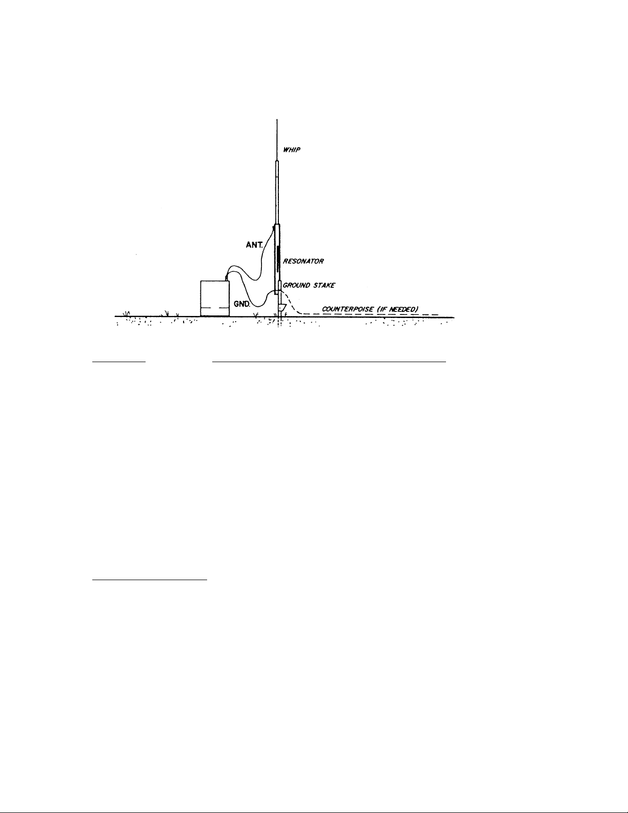
FIGURE 2 TUNEABLE WHIP ANTENNA OPERATION
The tuneable whip is an easily erected and transportable antenna, which may be easily tuned to
any frequency within its range. It is ideally suited where there are no supports for a doublet. The
antenna is not directional and needs a good ground for efficient operation. A counterpoise may
be needed if the ground is poor. Some notes for tuneable antennas (i.e., Spilsbury
Communications Ltd. STA-210 Series) are:
1. Connect wire from resonator unit to antenna (ANT) binding post. Connect wire from
ground stake to ground (GND) binding post.
2. Press the TUNE button and quickly adjust antenna for maximum indication on front
panel metre.
ADDITIONAL NOTE:
It will be noticed on different frequencies, that the metre will show different maximum
indications. This is normal, since the antenna impedance changes with frequency.

SECTION V - CIRCUIT DESCRIPTION
Refer to SBX-11A schematic while reading the following description. For location of P.C. board
components see the component layout diagram of the printed circuit board.
A. OSCILLATORS
1. The receiver channel oscillator is Q104. Its frequency is varied by the CLARIFIER C501.
Trimmer capacitors on each channel permit setting each crystal on frequency while the
CLARIFIER is centered.
2. The transmitter channel oscillator is Q106. It is similar to the receiver channel oscillator
but does not have a CLARIFIER frequency control. Each crystal has a trimmer capacitor.
3. The LFO operates at 456.5 kHz. C138 is used to adjust the oscillator to the correct
frequency.
B. RECEIVER
1. Q101, a FET emitter follower, couples the signal from the receiver input filter to the mixer
U101. In U101 the signal is amplified and mixed with the channel oscillator frequency -
producing the I.F. frequency which is fed to U102 through T101.
2. The signal is further amplified by U102, then passes through transformer T102 and
sideband filter FL101.
3. U103, which has two outputs (pin 6 and 8) amplifies the signal from FL101. The output
from pin 8 is rectified by D106 and D107 and the resultant DC controls the current through
Q102 which supplies the forward AGC bias for U101, U102, and U103.
4. The output from pin 6 is fed to T103 then to the balanced modulator/
demodulator FL102 through T-R switch diode D102. In FL102 this I.F. signal mixes with
the LFO signal from Q107 to produce the audio signals.
5. The audio is fed to volume control R1, to Q103 the audio preamp, and to U104 the audio
output, then to the speaker via C125.

C TRANSMITTER
1. The audio signal from the microphone is fed to Q113 through R.F. decoupling network
L110 and C166. The Darlington configuration of Q112 is used to match the impedance of
Q113 to the input of balanced modulator FL102.
2. The LFO (456.5 kHz) is fed into the double balanced mixer FL102 and is mixed with the
audio input signal from Q112.
3. A double sideband signal (suppressed carrier) results and is fed to the input of the sideband
filter FL101 via T-R switch diode D101. Diode D102 is biased off.
4. The upper sideband is removed by the sideband filter and the lower sideband is amplified
by U103 and fed to the transmitter balanced channel mixer FL103 through T-R switch
diode D108. D102 is biased off.
5. The channel oscillator frequency (H.F.O.) from Q106 is also fed into the balanced mixer
FL103 and the two main output frequencies are the channel oscillator frequency +/- the I.F.
frequency.
6. The transmitter filter ‘TX’ is tuned to select the lower of these two frequencies (which is an
upper sideband signal) and reject all other frequencies.
7. The desired channel frequency is now amplified by broadband amplifier IC U105, passes
through T106, is again amplified by push-pull broadband amplifier Q109 and Q110 and is
coupled to the tuned tank circuit ‘PA’ via T105.
8. Thermistor R150 stabilizes the bias over the temperature range of -30 Deg. C to +50 Deg.
C.
9. The output load impedance is nominally 50 Ohms but the SBX-11A will operate into 25 to
100 Ohms with very little reduction of power with no reloading.

10. Current transformer T1204 provides power output indication on the front panel metre and
also provides part of the ALC feedback voltage to the gate of the FET microphone
amplifier Q113. Part of the ALC is developed from voltage at the output. This advanced
ALC circuit senses power and so the output power is almost constant for loads between 25
and 100 Ohms,.
D. METERING
1. On receive the battery voltage is monitored on an expanded scale to permit determination
of battery condition.
2. The metre is automatically switched to monitor antenna output current on transmit.
E. MISCELLANEOUS
1. Q108 shorts out receiver B+ when switching from receive to transmit, to prevent feedback
from the speaker to the microphone during the switching interval.
2. Operate/Tune Switch
When in tune position a DC current is passed through double balanced mixer FL102
unbalancing it and permitting the LFO frequency to pass through it, through Diodes D101
and D102 (turned on by the Tune Button) into the 2nd double balanced mixer FL103. The
LFO input to FL103 produces the suppressed carrier frequency at the output which is used
for antenna tuning. The Tune Button can also be used to tune the transmitter into a dummy
load resistor.
3. Supply Protection
If the supply voltage exceeds about 18 V the zener diode D1 will conduct and blow the fuse
F1. (This should not occur with any of the power options offered for the SBX-11A). If the
supply polarity is reversed the zener diode will conduct in the forward direction and blow
the fuse.

SECTION VI - TUNING AND ALIGNMENT
A. CRYSTAL INFORMATION
Low Frequency Oscillator Crystal:
One required per radio.
Spilsbury Communications 85-311,frequency 456.500 kHz.
High Frequency Oscillator (H.F.O.) Transmitter and Receiver Crystals
One each required per channel. (Two total of same frequency)
Spilsbury Communications Part No. 85-222, frequency is calculated as follows:
1. Determine Assigned Frequency as per D.O.C. document.
2. Determine Suppressed Carrier Frequency by subtracting:
a) 1.5 kHz from the Assigned Frequency for Land Equipment
or
b) 1.4 kHz from the Assigned Frequency for a Ship Station
(Marine Use).
3. Add 456.5 kHz to the Suppressed Carrier Frequency. This is the Actual Crystal
Frequency
Crystals may be ordered from Spilsbury Communications Ltd. as follows:
by specifying Suppressed Carrier Frequency with suffix -SCF
or
by specifying Actual Crystal Frequency with suffix -Xtal

B. CHANNEL FILTER INFORMATION
Frequency
Range
Colour
Code
‘RX’
Filter
‘TX’
Filter
‘PA’
Filter
1.6 - 2.0 MHz White 01-214 01-219 01-206]
2.0 - 2.82 Black 01-215 01-220 01-207
2.82 - 4.0 Brown 01-216 01-221 01-208
4.0 - 5.66 Red 01-217 01-222 01-209
5.66 - 8.0 Orange 01-218 01-223 01-210
8.0 - 10.0 Yellow 01-394 01-395 01-396
Order ‘RX’, ‘TX’ and ‘PA’ Filter Kits by frequency colour code. Order individual filters by Part
No. A complete ‘RX’, ‘TX’ and ‘PA’ Kit can be ordered by colour code if the two frequencies
are within the frequency range.
C. Main Chassis Removal
1. Unlatch top cover.
2. Unlatch battery box and disconnect battery plug.
3. Loosen the two screws on the back cover about 1/8" and holding onto the outside case,
push rear of the chassis with thumbs to break the chassis loose from the rubber seal.
4. Remove screws completely and finish removing chassis carefully.

D. Tuning to Channel Frequencies
1. Minimum test equipment necessary
(a) Standard signal generator with a calibrated low impedance output (50 Ohms or
less)
(b) A frequency counter with accuracy of 1 part in 10(6) or preferably 10(7) Hz with an
input sensitivity of .01 Volts at 1 MegOhm.
(c) A 50 Ohm non-reactive dummy load resistor.
(d) A 500 mA R. F. ammetre.
(e) An audio output metre.
(f) An oscilloscope useable to 8 MHz or an R.F. VTVM.
(g) A regulated 12 Volt, 2 Amp power supply.
2. Installation of Channel Components.
(a) Remove crystal clamp and P.A. tank coil cover can.
(b) Install TX and RX crystals in the desired channel positions.
(c) Install TX filters and RX filters in the desired channel positions. The filters are
marked on the pin side with T and R and an arrow which corresponds to the arrows
on the printed circuit board.
(d) Install P.A. tank coils in the desired channel positions. Note the coloured stripe on
the base of the P.A. coils - the stripe should line up with the stripe of the printed
circuit board.
(e) Replace crystal clamp and P.A. tank coil cover can. The screws and nuts holding
these components to the printed circuit board should be tightened firmly but not so
that damage to the components occurs.

D. Tuning to Channel Frequencies (Cont’d)
3. Adjustment of Crystal Frequencies
(a) Adjust the speech clarifier control so the arrow points directly up (toward top of front
panel).
(b) Turn the power on and measure the frequency at the RX H.F.O. test jack (on main
printed circuit board). Use a coupling capacitor between the test jack and the counter
of not greater than 10 pF capacity.
(c) Adjust the RX crystal trimmer screw of the channel being tuned until the counter
reads the crystal frequency stamped on top of the crystal case.
(d) Transfer the counter test probe to the TX H.F.O. test jack using the same coupling
capacitor.
(e) Press the P.T.T. button on the microphone and adjust the TX crystal trimmer screw of
the channel being tuned until the TX crystals are on their correct frequencies.
4. Receiver Tuning to Channel Frequencies
(a) Connect the signal generator to the ANT-GND terminals, and the audio metre across
the speaker terminals.
(b) Inject an unmodulated R.F. signal of the channel frequency desired, at a level of 0.1
Volt.
(c) With the volume turned midway CW tune the signal generator carefully until an audio
note of about 1000 Hz is heard.
(d) Reduce the level of the signal generator until the audio voltage across the speaker is
about 1 Volt.
(e) Tune the slugs of the receiver channel filter being tuned from the ‘all out’ position
(slugs flush with top of coil can) until an increase in sensitivity is noted.

D. Tuning to Channel Frequencies (Cont’d)
(f) As the sensitivity increases always adjust the signal input level to maintain about 1
Volt across the speaker.
(g) When nearing maximum sensitivity the volume control may have to be adjusted
somewhat to reduce the level across the speaker, thereby avoiding overloading of the
audio amplifier.
(h) Remove the audio meter and signal generator connections before beginning
transmitting tuning.
5. Transmitter Tuning to Channel Frequencies
NOTE: Carrier, Bias, Gain and ALC controls for the transmitter have been set correctly at
the factory. They should not be adjusted unless the complete alignment
instructions are followed. (See Section E Basic Tuning).
(a) Connect the 50 Ohm dummy load with the R.F. milliameter in series across the ANT-
GND terminals.
(b) Press the TUNE button while making the following adjustments.
(c) Tune the slugs of the transmitter channel filter being tuned from the ‘all out’ position
(slugs flush with top of coil can) until the R.F. ammeter begins to indicate. A
sensitive oscilloscope or an R.F. VTVM connected across the load will give a better
initial indication. It is best to alternately tune each coil of the coil of the filter in small
steps until this point is reached.
(d) Tune the slug in the P.A. tank coil of the channel being tuned from the ‘all in’
position until the R.F. ammeter indicates a peak.
(e) Tune the transmitter filter coils, tank coil and loading capacitor alternately of the
channel being tuned to get maximum output. Whenever the output exceeds 0.3A
detune the input coil of the transmitter filter COUNTER CLOCKWISE for a reading
of 0.3A. The input coil of the transmitter filter is adjacent to the crystals. The 0.3A
output figure applies only with a power supply voltage of 12 Volts.

(e) (Cont’d)
Supply Voltage Output Current
10V .27A
11V .28A
12V .29A
13V .31A
NOTE: These are theoretical values that assume a measurement accuracy of at least 3%.
As this is unnecessary the 12V figure is rounded up to 0.3A in the rest of the text.
Do not attempt to tune the transmitter with batteries or a power supply on which
the output voltage varies with the amount of load.
NOTE: The loading capacitor tuning is very broad at the lower frequencies. If the peak is
not quite reached at minimum capacity, remove the coil can cover and remove
from the appropriate tank coil the appropriate capacitor connected to the pins on
either side of the coloured strip on the base of the coil. (Do not remove unless
necessary).
(f) Loosely couple a counter to the R.F. output and check that the transmitter output
frequency is equal to the crystal frequency 456.5 kHz.
(g) Release the TUNE button.
(h) Speak into the microphone. The metre should indicate to the right.
(i) Return the set to its case and close the battery box. The set is now ready for use
following the instructions in the cover.
Table of contents


