spinflo S~OH70000Y Operating instructions
PCC 1265Y
–
Issue 2
FOR USE IN USA & CANADA
USER AND INSTALLATION INSTRUCTIONS
READ AND RETAIN FOR FUTURE REFERENCE
MODELS
S~OH70000Y - TRIPLEX
S~OH71000Y – TRIPLEX DUAL FUEL
SPINFLO LIMITED, 19 Oakham Drive, Parkwood Industrial Estate
Rutland Road, Sheffield S3 9QY, ENGLAND.
TEL: + 44 (0) 114 273 8157 FAX: + 44 (0) 114 275 3094
BUILD IN APPLIANCES
FOR USE WITH LIQUIFIED PETROLEUM GAS
C
O
U
N
T
R
Y
L E I S U R E

- Do not store or use gasoline or other
flammable vapors and liquids in the vicinity
of this or any other appliance.
- WHAT TO DO IF YOU SMELL GAS
•Do not try to light any appliance
•Do not touch any electrical switch
•Do not use any phone in your recreational
vehicle
•Clear the recreational vehicle of all
occupants.
•Turn off the gas supply tank valve(s) or
main gas supply.
•Immediately call your gas supplier for
instructions.
•If you cannot reach your gas supplier, call
the fire department.
- Have the gas system checked and leakage
source corrected by a qualified installer,
service agency, manufacturer or dealer or
the gas supplier.
WARNING:
If the information in this manual is not
followed exactly, a fire or explosion may
result causing property damage, personal
in
j
ur
y
or death.
2

3

4
5
6

7

SPECIFICATION
Gas:
TRIPLEX TRIPLEX
PROPANE gas only 11 ins wc ( 27.4mbar )
TRIPLEX TRIPLEX TRIPLEX
Model S~OH70000Y S~OH71000YRange S~OH70000Y S~OH70000Y S~OH70000Y
External
Dimension
(HxWxD)
468 x 456 x 500mm
18.43 x17.95 x19.70in 468 x 456 x 500mm
18.43 x17.95 x19.70in
mm
Inches
468 x 456 x 500mm
18.43 x 17.95 x 19.70in 468 x 456 x 500mm
18.43 x17.95 x19.70in 468 x 456 x 500mm
18.43 x17.95 x19.70in
Oven
Capacity 36
2200 36
2200
Litres
Cubic ins 36
2200 36
2200 36
2200
No. of tra Grill 2, Oven 4 Grill 2, Oven 4
y positions Grill 2, Oven 4 Grill 2, Oven 4 Grill 2, Oven 4
Heat input
Total heat input
Hotplate Burners (LPG) 2 x 5350 Btu/hr
1 x 7850 Btu/hr 2 x 5350 Btu/hr3 x 5350 Btu/hr
2 x 5350 Btu/hr
AUX 1 x 3450 Btu/hr 2 x 4400 Btu/hr
AUX 1 x 3450 Btu/hr
Electric Hot
(110V ~ 60Hz) N/A 1 x 1000W Maxplate N/A N/A N/A
Grill burner heat input 4900 Btu/hr 4900 Btu/hr4900 Btu/hr 4900 Btu/hr 4900 Btu/hr
Oven burner heat input 5700 Btu/hr 5700 Btu/hr5700 Btu/hr 5700 Btu/hr 5700 Btu/hr
Injector size,
mm
Hotplate Burners Sabaf 2x0.67, 1x0.81 Sabaf 2x0.67Sabaf 0.67 Sabaf 2x0.67, 1x0.53 Sabaf 2x0.62, 1x0.53
Grill burner Sabaf 0.62 Sabaf 0.62Sabaf 0.62 Sabaf 0.62 Sabaf 0.62
Oven burner Sabaf 0.65 Sabaf 0.65Sabaf 0.65 Sabaf 0.65 Sabaf 0.65
By
pass size, mm
Hotplate Controls Sabaf 0.34 Sabaf 0.34Sabaf 0.34 Sabaf 0.34 Sabaf 0.34
Grill control N/A N/AN/A N/A N/A
Oven contro Sabaf 0.35 Sabaf 0.35l Sabaf 0.35 Sabaf 0.35 Sabaf 0.35
Spark ignition 12V 12V(If fitted) 12V 12V 12V
Weight
21.5Kg
47.4lbs 23.1Kg
50.9lbs
Kg
Pounds 21.5Kg
47.4lbs 21.5Kg
47.4lbs 21.5Kg
47.4lbs
IMPORTANT
•THIS APPLIANCE IS SUITABLE FOR USE WITH PROPANE AND
SHOULD NOT BE USED ON ANY OTHER GAS.
•USE ONLY THE GAS PRESSURES SPECIFIED ABOVE
•THIS APPLIANCE MUST BE EARTHED.

INTRODIONUCT
In your own interest of safety, gas applianc
Failure to install the appliance correctly coul
This appliance shall be installed in accor
instructions, local and state codes or, in t
Recreational Vehic
es
d
ab
sh
inv
se
oul
alid
nc
d in led by competent persons.
a or liability claims.
e e u o ith the Standard for
, ANSI A119.2.
be
te a
of s
stal
y w
ch c
n arra
de
nty
s, w
dance with the manufacturers installation
h
les
Data label
The data label is locat
oven door. Ensure that the gas supply is Pr
with Propane gas and should not be conv
ed on the right hand si
erted for use with any other gas.
de front of the oven compartment, behind the
opane. This appliance is designed for use
Provision of Ventilation e s o ti f heat and moi e in a
ll ventilated and in accordance
obstruct the flow of combustion or ventilation ir
e adequate ventilation for complete combustion of gas,
mperature mmediate surroundings within safe limits.
The use of a gas cooking applianc
room in which it is installed.
with local and state codes. Do not
general, the appliance should hav
proper flueing and to maintain
Location
t.
This appliance maybe installed in a kitchen/ki
bath or a shower. LP gas appliances must
b
tchen diner but NOT in a room containing a
not be fitte e level. e
as d b low ground
emen .g. in a
result in the pr duc on o
Ensure that the kitchen is we
te of i
stur
a . In
OPERATION
WARNING
•The appliance is NOT intended for use by young children or
infirm persons, without supervision
•Glass lids may shatter when heated. Turn off all burners
efore shutting the lidb
•Spillage on the lid surface should be removed before opening.
Burner operation
The burners on this appliance have fixed aeration and no adjustment is required. The
burners should flame as follows:-
Propane - The flames should burn quietly with a blue/green colour with
no sign of yellow tips.
IMPORTANT
Although each burner will support pans from 4ins (100mm) to
For safe operation burner flames should be adjusted so they do NOT
extend beyond the edge of the pan as this will reduce the efficiency
of the burner.
•Avoid old or misshapen pans as these may cause instability.
•
•8½ins (220mm), care should be taken not to overload the appliance
as reduced performance may result.
•
The lid must be opened fully when using the hotplate burners.
Using the Hob Burners
. Ensure gas cylinder/supply is connected and turned on. In the event of a gas smell turn
off at gas cylinder/mains and contact supplier.
. Flame supervision: Each burner is controlled individually and is monitored by a
thermocouple probe. In the event of the burner flames being accidentally extinguished,
turn off the burner control and do not attempt to re-ignite the burner for at least one
minute.
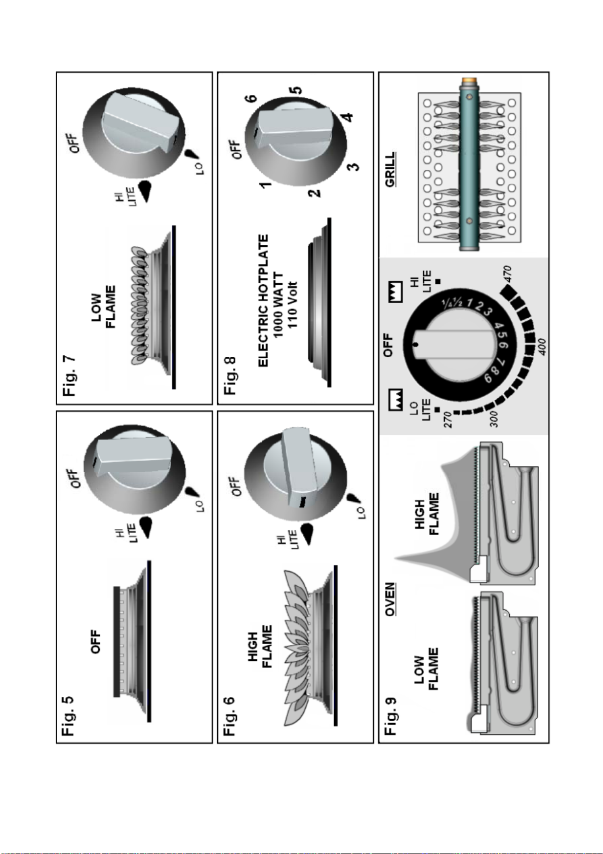
. To light: Push in the control knob and turn to ‘LITE’ position – see Fig.6. Hold a lighted
match or taper to the burner and push the control knob in and hold. It is necessary to
hold the knob depressed after the burner has ignited for approximately 10 - 15
seconds, to allow the thermocouple probe to reach temperature, before releasing the
knob. Should the flame go out when the knob is released, the procedure should be
repeated holding the knob depressed for slightly longer.
. For models fitted with Spark Ignition the procedure is similar except that the burner can
be ignited by depressing the ignition button, which is located on the fascia. If the burner
has not lit within 15 seconds the control knob should be released and the burner left for
at least 1 minute before a further attempt to ignite the burner.
. For simmering, turn the knob further anti-clockwise to the low rate position –see Fig. 7
. To turn off: Turn the control knob until the line on the control knob is aligned with ‘OFF’
on the control panel. Always make sure the control knob is in the ‘OFF’ position when
you have finished using the hotplate burners – see Fig. 5.
1
2
3
4
5
6
10

OPERATION
sing the Electric Hotplate
WARNING
•Glass lids may shatter when heated. Turn off the hotplate and allow it to
re opening.
cool before closing the glass lid.
•Remove all spillage from the surface of the glass lid befo
U
om 1 to 6 – see Fig. 8. To turn it on, rotate the knob
oolest setting.
ho
‘OFF’ on the
T sealed construction and transfers heat through conduction. For maximum
efficien a n size
should be t
Before sin
season .
To prime th
Switch n t the coating.
se a edi uring this
hen season.
me
app
Ensure the electricity is switched on.
he hotplate control is numbered frT
either clockwise or anti-clockwise to the required position. Position 1 is the c
To turn the ob until the line or pointer on the knob lines up withtplate off, rotate the kn
control panel.
he hotplate is a
cy correctly sized pan with a flat heavy gauge base should be used. Pa
he same or slightly larger (up to 1” / 2.5 cm oversize).
u g your hotplate for the first time, we recommend that you prime and then
it
e Hotplate
a ro he hotpl te fo a short period, without a pan, to harden and burn off
m um to high setting for 3 – 5 minutes. A non toxic smoke may occur dU
process. Allow it to cool, t
To season the Hotplate
First heat the hotplate for 30 seconds on a medium setting, then switch off. Pour a minimal
ount of unsalted vegetable oil onto a clean dry cam loth or paper towel, and apply a thin
coat of oil to the hotplate surface. Wipe off any excess oil, then heat the hotplate on a
dium setting for 1 minute. Occasional seasoning will help to maintain the Hotplate’s
earance.
11

OPERATION
IMPORTANT
•
•The grill MUST only be used with the door open.
The control tap on this appliance operates both the Grill and Oven
b
•Tg
the grill. Never adjust the heat deflector position without using hand
protection – ie oven gloves.
burners. To ensure safe operation it is not possible to operate both
urners at the same time.
he heat deflector below the fascia should be pulled out prior to lightin
Using the Grill
. Ensure gas cylinder/supply is conn1
ected and turned on. In the event of a gas smell turn
an
n the fascia. Ignition
nds
ignite the burner.
it should be heated for about 20 minutes to eliminate any
kly, it is recommended that a few minutes preheat
o
y on Butane.
. A reversible grill pan trivet enables the correct grilling height to be achieved.
Fast Toasting trivet in high position
Grilling Sausages trivet in high position
Grilling Steak/Bacon trivet in high position
Grilling Chops, etc trivet in low position
Slow Grilling trivet removed
9. To turn off: turn the control knob until the line on the control knob is aligned with ‘OFF’
on the control panel. Always make sure the control knob is in the off position when you
have finished grilling.
off at gas cylinder/mains and contact supplier.
2. To light: Open door, push in the control knob and turn to ‘LITE’ position – see Fig 9.
Hold a lighted match or taper to the burner and push the control knob in and hold. The
burner should ignite and the control knob should be held in for 10 -15 seconds before
release. If the burner goes out, repeat procedure holding control knob for slightly
longer.
3. For models fitted with Spark Ignition the procedure is similar except that the burner c
be ignited by depressing the ignition button, which is located o
must be carried out with the door open, and if the burner has not lit within 15 seco
the control knob should be released and the grill left for at least 1 minute before a
further attempt to
4. On first use of the grill,
residual factory lubricants that might impart unpleasant smells to the food being
cooked. A non-toxic smoke may occur when using for the first time so open any
windows and turn on mechanical ventilators to help remove the smoke.
5. Although the grill does heat up quic
be allowed.
6. Flame Failure Device (FFD): the grill burner is fitted with a flame sensing probe, which
will automatically cut off the gas supply in the event of the flame going out. In the event
of the burner flames being accidentally extinguished, turn off the burner control and d
not attempt to re-ignite the burner for at least one minute.
7. It is normal for the flames on this burner to develop yellow tips as it heats up,
particularl
8
IMPORTANT
•The pan supplied is multi functional, for use whilst grilling or when using
the oven. The handle design allows removal or insertion whilst the pan is
in use. Always remove the handle when the pan is in use.
12

OPERATION
WARNING
•When cooking always ensure young children are kept away.
•Never cover slots, holes or passages in the oven bottom or cover an
uch as aluminium foil. Doing so blocksentire shelf with materials s
airflow through the oven and may cause carbon monoxide poisoning.
Aluminium foil linings may also trap heat, causing a fire hazard.
Using the Oven
ual
A
turn
f the
1. Ensure gas cylinder/supply is connected and turned on. In the event of a gas smell turn
off at gas cylinder/mains and contact supplier.
2. To light: Open door, push in the control knob and turn to ‘LITE’ position – see Fig. 9.
Hold a lighted match or taper to the burner and push the control knob in and hold. The
burner should ignite and the control knob should be held in for 10 -15 seconds before
release. If the burner goes out, repeat procedure holding control knob for slightly
longer.
For mod3. els fitted with Spark Ignition the procedure is similar except that the burner can
be ignited by depressing the ignition button, which is located on the fascia. Ignition
must be carried out with the door open, and if the burner has not lit within 15 seconds
the control knob should be released and the oven left for at least 1 minute before a
further attempt to ignite the burner.
4. Place the oven shelf in the required position and close the door. Set control knob to
approximately 3500F and heat the oven for about 30 minutes to eliminate any resid
factory lubricants that might impart unpleasant smells to the meals being cooked.
non-toxic smoke may occur when using for the first time so open any windows and
on mechanical ventilators to help remove the smoke.
5. Although the oven does heat up quickly, it is recommended that a 10 minutes preheat
be allowed. The oven should be up to full temperature in about 15-20mins.
6. To turn off: turn the control knob until the line on the control knob is aligned with ‘OFF’
on the control panel.
7. Shelf: the shelf has been designed to allow good circulation at the rear of the oven and
includes a raised bar to prevent trays or dishes making contact with the back o
oven. To remove a shelf, pull forward until it stops, raise at front and remove.
Oven Temperature Control
T the oven is controlled b
th r 65 F (130°C to 240°C). Approximate temperature
th c shown in the table be
he temperature in y a thermostatic gas tap and is variable over
e ange 2660F to 4 s for the settings on
e ontrol knob are low. The temperatures indicated refer to the
fferent temperatures may be cooked at the same time. In this
way maximum benefit can be obtained from the gas used to heat the oven. Care should be
taken not to overload the oven, adequate spacing being used to allow free circulation for
heat.
0
centre of the oven and at any particular setting the oven will be hotter at the top and cooler
towards the base. The variation between top and centre, and centre to bottom is
approximately equivalent to 300F. Good use can be made of the temperature variation in
several dishes requiring di
13

OPERATION
Cooking Guidelines
Best r
page. s oven
is capable
Most cook
recipe. If n find a
imilar dish in our guide and use our shelf position and gas mark setting recommendation.
from the top down. When roasting with aluminium foil care must be
ken that the foil does not impair circulation or block the oven flue outlet.
Do
esults will be obtained by the shelf positions in this guide – please see chart on next
It i not necessary to preheat the oven but advisable for a range of dishes. The
of full temperature in 15-20 minutes.
ery books give details of the shelf positions and gas mark settings for each
in doubt about a recipe you intend to use, study the recipe carefully the
s
Shelf positions are
ta
's And Don'ts
DO read the instructions carefully before first use of the appliance
pliance regularly.
DO turn pan handles away from the front to avoid accidents
ar the cooker when in use.
O NOT allow fats or oils to build up in the oven trays or base.
DO allow the oven to heat before first use, to expel smells
DO clean the ap
DO remove spills as soon as they occur.
DO always use oven gloves when removing food shelves and trays.
DO check that controls are in the ‘OFF’ position when finished.
DO NOT allow children ne
D
DO NOT use abrasive cleaners or powders to clean the surfaces of the appliance.
DO NOT under any circumstances use the oven as a space heater.
DO NOT put heavy objects onto open grill and oven doors.
DO NOT reach over a lit appliance to gain access to overhead storage cabinets
Temperature
oF oC
¼ - ½ 255-275 120-135 Very cool Meringues
1 285 140 Cool Stewed fruit
2 300 150 Cool Rich fruit cake
3 330 165 Warm Baked custard
4 355 180 Moderate Victoria sandwich
5 385 195 Fairly hot Whisked sponges
6 410 210 Hot Short crust pastry
7 430 220 Hot Bread, scones
8 445 230 Very hot Puff pastry
9 465/480Max 240/260Max Very hot Quick browning
Shelf Cooking Time
Dish Pos
Scones 7 2 8-15mins
Small cakes 5 2 15-25mins
Victoria sandwich 4 2 20-30mins
Very rich fruit cake 2 2 Approx. 60mins per 500g
Puff pastry 8 2 15-30mins
Flaky pastry 7 2 15-30mins
Shortcrust pastry 6 2 15-55mins
Shortbread fingers 3 2 25-30mins
Ginger nuts 5 2 12-16mins
Rice pudding 2 3 100-120mins
Baked custard 3 3 50-60mins
Fruit crumble 5 3 30-40mins
Beef 3
7 3
3 25min per 500g plus 25min
15min per 500g plus 20min
Pork 3
7 3
3 30min per 500g plus 35
25min per 500g plus 25min
min
WARNING
•Never use this appliance as a space heater to heat or warm the room.
Doing so may result in carbon monoxide poisoning and overheating of
the oven
•Never use the oven as storage space. Doing so may result in a fire
and/or cause incomplete combustion.
14
OPERATION
Leaks
a smell of gas becomIf es apparent, the supply should be turned off at the cylinder
IMMEDIATELY. Extinguish naked lights including cigarettes and pipes. Do not operate
electrical switches. Open all doors and windows to disperse any gas. Propane gas is
heavier than air; any escaping gas will therefore collect at a low level. The strong that
bnormal Operation
unpleasant smell of gas will enable the general area of the leak to be detected. Check
the gas is not escaping from an unlighted appliance. Never check for leaks with a naked
flame, leak investigation should be conducted according to the following instructions.
A
of the are onside ed to be
•Yellow tipping of burner flame.
Burners not igniting properly.
B er h
Burners exting upb
a t to
Any following c r abnormal operation and may require servicing.
•Sooting of cooking utensils.
•
•urn s failing to remain alig t
•uished by c oard doors.
•Gas valves th t are difficul turn
W
O
he
Owhile it is in operation.
Ens
or motor homes.
•NEVER check for leaks with an open flame
ARNINGS
•D NOT store or use gasoline or other flammable vapours, liquids or items in
t vicinity of this or any other appliance.
•D NOT spray aerosols in the vicinity of this appliance
•N VER use the appliance as a space heater, either in marine craft, carava
15

INSTALLATION
Regulations and Standards
own interest of safety, gas appliances should be installed by competent persons.
ms.
for
In your
Failure to install the appliance correctly could invalidate any warranty or liability clai
This appliance shall be installed in accordance with the manufacturers installation
instructions, local and state codes or, in the absence of such codes, with the Standard
Recreational Vehicles, ANSI A119.2.
Data label.
The data label is located on the right hand side front of the oven compartment, behind the
ven door. Ensure that the gas supply is Propane. This appliance is designed for use
ith Propane gas and should not be converted for use with any other gas.
o
w
Ventilation
This appliance is suitable for installation into Holiday Homes, Touring Caravans and Boats.
In all cases the national standards with regard to ventilation for the particular vehicle into
which the appliance is to be
The appliance Mosure having the following ventilation:-
•A g esc eneath the appliance and positioned
at t rea T vent to the outside and have a cross-
sectional ar 2 ) and should be baffled to
pre nt di
•A h h lev liance in either the worktop or direct to
the outside – see ×Fig. 1 & 2, with a cross sectional area of minimum 4in2
(2400mm2). If vented to the outside a baffle should be attached to prevent direct
draught to the appliance.
Location of Appliance
installed must be adhered to.
UST be installed into an encl
as ape hole in the floor, directly b
he r – see ¯Fig. 2. The hole MUS
2 2
ea between 3in and 6in (1965 to 3850mm
ve rect draught to the appliance.
ig el rear vent, directly behind the app
This appliance maybe installed in a kitchen/kitchen diner but NOT in a room containing a
bath or a shower. LP gas appliances must not be fitted below ground level. e.g. basement.
Choose a location free of draughts, open doors and clear of combustible materials and
other fire hazards. The location should ensure convenience of operation and service. Any
adjoining wall surface situated within 41/2 in (115mm) from the cooker side – see Fig. 3,
must be made from a suitable non-combustible material for a height of 6in (150mm) for
the hotplate.the entire length of
Position
CAUTION: DO NOT LIFT APPLIANCE USING THE DOOR HANDLES
The appliance must be installed in such a
follows
becaus o
tempe u
Temp n Procedure
way that the furniture fitted around the unit
the minimum dimensions as shown in Figs. 1, 2 & 3. If this cannot be adhered to
f design constraints, then the design is deeemed permissible providing that the
rat re rise on the furniture is tested by undertaking following procedure.
erature Verificatio
Pla ate burners and fill up 3/4with
water. Turn on all 3 hotplates and the oven on full. After 45 minutes turn off the
oven and turn on the grill to full. After a further 15mins establish the highest
temperature points on ALL the furniture surfaces in direct line of sight of the
appliance. The temperature rise must not exceed 1490F ( 65oC) above the ambient
temperature, or where applicable, must not exceed the maximum allowable
temperature, to avoid damage, as detailed within the material suppliers
specification.
ce 3 large pans (20-22cm Ø) on top of the hotpl
16

INSTALLATION
All Appliances – The maximum depth of overhead cabinets installed above the cooker
cal
Fixing
must NOT exceed 13ins (330mm). All combustible materials such as curtains and shelves
must be kept well clear of the appliance, and their installation should meet all relevant lo
and state regulations/standards in force.
The
me se appliances can be front or side fixed, holes are provided for either installation
thod. Fixing screw positions are located as follows.
Gas Connection
A ¼ NPT female connection is provided for gas inlet, on the rear of the appliance. It is
on – 27.4mbar)
et to the correct pressure for the type of gas
bei
If th e that
the sooting)
the d
not
The burners on this appliance hav
Appl
recommended that the appliance be connected by copper tubing, a rubber or hose
connection must not be used. After connection the appliance must be tested for
soundness.
This appliance is suitable for use
Propane Gas Only 11 ins wc (
Max regulator inlet pressure ½ ins psi (34.5mbar)
Regulator supply pressure 12 ins wc (30.0mbar)
Manifold working pressure 11 ins wc (27.5mbar)
It is important that the regulator should be s
ng used. Excessive pressure must not be permitted.
e flame on either the top burners or the grill show a tendency to lift, it is probabl
line pressure is too great. Should there be excessive yellow tips (resulting in
n it is probable that the line pressure is too low and, in either case, the burners shoul
be used until the line pressure has been checked.
e fixed aeration and no adjustment is necessary.
iance Front Fixed Appliance Side Fixed Appliance
S~OH&
70000Y 2
S~OH71000Y
front fix holes each side of
Oven opening
s each hotplate side trim
2 side
2 fix hole
fix holes each side of
Oven opening
2 fix holes each hotplate side trim
IMPORTANT
•This appliance must be installed into an aperture, sealed off at either side in
order to prevent draughts from adjoining cupboards/vents. Ensure that air vents
and gas escape holes are kept clear, holes for cables and pipes mu
st be sized to
minimize air leakage between compartments.
r no circumstances should the ventilation hole exceed 3850mm2or other
aled to prevent a gas escape
•Unde
low level ventilation be located in the compartment, including vents in kickboards.
Low level vents in adjacent compartments are permitted.
•Any cupboards beneath the appliance MUST be se
entering the living area.
17

INSTALLATION
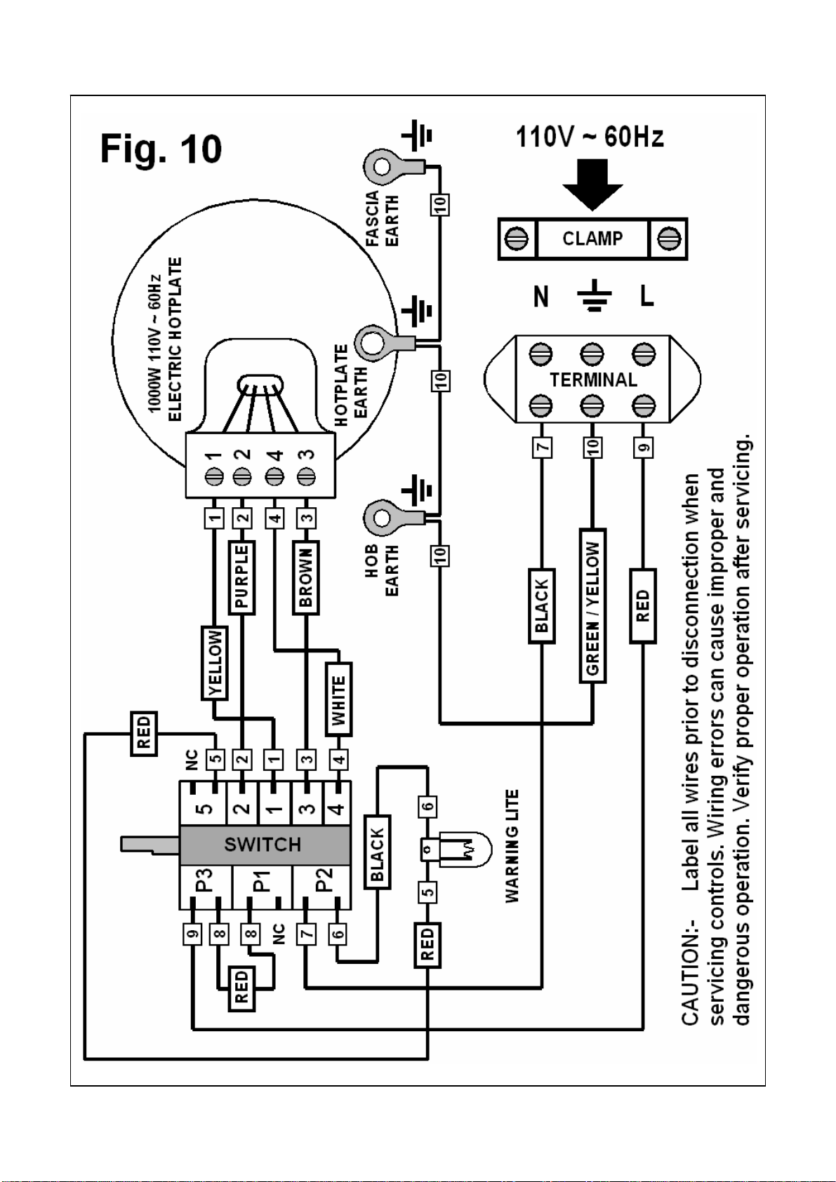
Dual Fuel Appliances - Electrical Connection
This appliance must be connected using a double insulated cord, type 227 IEC 53,
HO5V V-F, which is suitable for use up to 4 amps. See Fig 4 for terminal connection
etails. This should be connected to a double pole switched mains supply, with 3mm
minimum contact separation at all poles. The supply cord must be retained using the
attached cable clamp and routed to the side through the supplied ‘P’ clip. Excess cord
m s n
body
All Mod
d
u t be routed away from the appliance and must not come into contact with the ove
or hang loose into the lower compartment.
els
liance must be electrically grounded in accordaThe a p in
the a e
Models
pnce with state or other codes or,
bs nce of such codes, with the National Electrical Code, ANSI / NFPA 70.
with 12Volt Spark Ignition
Conn c
terminals located on the spark ignition generator. A supply cord terminating in sheathed
spade connectors is recommended. The supply cord should be retained against the rear
upport leg using a ‘P’ clip and routed away from the appliance.
e tion to the 12volt electrical supply of the recreational vehicle is made via the spade
appliance s
All Models – Pressure Testing
The appliance and its individual shutoff valve must be disconnected from the gas sup
piping system during any pressure testing of the system ply
at test pressures in excess of
½ psi (3.5kPa).
vthe
l
e
service provider in your area.
The appliance must b
manual shutoff
ressures equa
e isolated from the gas supply system be closing its individual
alve during any pressure testing of
to or less the ½ psi (3.5kPa). gas supply piping system at test
p
When satisfied with the appliance and after instructing the user on the correct
method of operation, these instructions MUST be left with the appliance. If th
appliance fails to operate correctly after all checks have been made, refer to the
uthoriseda
IMPORTANT
•After installation the appliance MUST be tested for soundness
•Test ALL burners on high and low flame for flame stability.
•The gas supply input pressure MUST NOT rise or fall significantly from
eived/witnessed.
nominal when ALL appliances connected to the supply are operated
simultaneously. If NOT installed to the manufacturers instructions detailed
herein, we the manufacturer can not be held responsible for any problems
that occur, or poor performance that is perc
18

MAINTENANCE & SERVICING
aners, steel wool or cleansing powders.
hen cleaning the burner ring it is essential to ensure that the holes do not become
terchangeable without affecting the sense of operation.
This appliance needs little maintenance other than cleaning. All parts should be cleaned
using warm soapy water. Do not use abrasive cle
IMPORTANT
•All servicing must be carried out by an approved competent person.
•After each service the appliance must be checked for gas soundness
W
blocked.
The control knobs are a push fit and can be removed for cleaning. They are
in
Who To Contact
For service, please contact your authorised local Service Agent giving full details of the
model, serial number and date of purchase.
All Models Leak Detection Test Method
following procedures should only be carried out by an
st
the end of the manifold near the gas regulator.
1. Leak testing of manifold f
Turn all control valves to High (max) setting. Pressurize the system – max 60 ins
wc (150mbar). Verify all control valves are gas sound – ie no pressure loss.
m –
rify the control valve and pipework to the
respective burner are gas sound – ie no pressure loss. Repeat for each of the
control valves and gas circuit.
In all cases if a leak is detected its location should be established by using leak detector
spray following which remedial action should be taken.
In your own interest of safety the
approved competent person. Before commencing any leak testing Isolate the appliance
from the gas supply. For each test the system should be pressurized via the pressure te
point located on
Pressurize the system – max 60 ins wc (150mbar). Verify gas soundness o
manifold – ie no pressure loss.
2. Leak testing control valves
3. Leak testing individual control valves and pipe work
Turn on the control valve to be tested to a High setting. Pressurize the syste
max 60 ins wc (150mbar). Temporaily block the respective burner jet and
depress the control valve knob. Ve
19

MAINTENANCE & SERVICING
Service Instructions
1s supply.
the appliance is Dual Fuel, disconnect/isolate the electric supply.
2. emove hob surface
nd
fascia retaining screws. Carefully lift off the fascia and if spark ignition fitted
remove the two spade connectors from the rear of the toggle switch. Remove the
ove the two
ed through the outer slots on
the angled front. Grasp the hob by the angled front face, carefully lift the hob
the front to allow the rear edge to unhook from the rear box section. e
e put onto a suitable surface.
3. Remove appliance from housing n the oven door and remove the 2 screws from
pply lead from rear
nce out onto a suitable surface.
4. Co
Ho emove hob surface (2). Unscrew the
cor
Op rear of oven. Remove
the
pip it on
the
Ov
As above instructions but remove appliance from housing to gain access to the
oven thermostat, grill and oven thermocouples.
ce from housing (3). Remove hob
surface (2). Remove the two screws retaining the heat deflector. Remove the
insulation wrap and lever off the two starlock washers retaining the grill burner. Lift
out the burner assembly.
. isconnect from gas supplyD
Lift and remove the bottom plinth to gain access, then disconnect the ga
If
R
Disconnect from gas supply (1) and electric supply if Dual Fuel. Lift off the Panrest
and remove the two screws securing each burner spreader. Remove front fascia by
removing all push on control knobs and unscrew the two recessed fixed nuts a
both
two central screws securing the pressing to the rear box section. Rem
front retaining screws located each side and access
surface from
Note:- On Dual Fuel appliances, remove the hotplate rear cover and disconnect th
power leads. The hob surface should b
Disconnect from gas supply (1). Ope
each side trim - note the appliance can either be front or side fixed, see under
Fixing, page 17. Open the glass lid and remove the 2 screws from each side trim.
Carefully slide the appliance out one third and check for any possible snagging of
wires or pipes. If the appliance is Dual Fuel, disconnect su
terminal block. If OK, lift applia
ntrol replacement
b controls
Disconnect from gas supply (1). R
responding pipe and thermocouple and remove from the control.
en the oven door and unscrew the 2 screws holding the thermostat probe in
position and push the probe back out through the hole in the
retaining screws from on top and underneath the control. Disconnect the inlet
e and two burner supply pipes. Remove the fittings off the old control and f
replacement.
en and Grill control
5. Remove the grill burner
Disconnect from gas supply (1). Remove applian
20
This manual suits for next models
1
Table of contents
Languages:
Other spinflo Cooker manuals

Popular Cooker manuals by other brands


Beko
Beko DVC665 Installation & operating instructions and cooking guidance

STOVES
STOVES SFG60DOP Users guide & installation handbook

Electrolux
Electrolux EH L20-4 user manual

Bosch
Bosch HXQ38AE5 M Series instruction manual

Tricity Bendix
Tricity Bendix SB432 Operating & installation instructions

Bosch
Bosch HGD4321.0M instruction manual

STOVES
STOVES ELLINGWOOD & BELMONT user manual

Beko
Beko DCC4521 Installation & operating instructions and cooking guidance

Olympia
Olympia GD155 instruction manual

Hotpoint
Hotpoint EW74 Instructions for installation and use

Zanussi Electrolux
Zanussi Electrolux ZCE 640 Instruction booklet

inventum
inventum VFI6042RVS instruction manual