Spirax Sarco DT300F User manual

EXPERTISE SOLUTIONS SUSTAINABILITY
3.333.5275.247 Issue 7.1 - 2013
© Copyright 2009
DT300F
Thermodynamic Steam Traps
Installation and Maintenance Instructions
1. General safety information
2. General product information
3. Installation
4. Commissioning
5. Operation
6. Maintenance
7. Spare parts
The PED Directive 97/23/EC is repealed and replaced by the new
PED Directive 2014/68/EU with effect from 19 July 2016.

3.333.5275.247
2

ATTENZIONE
Lavorare in sicurezza con apparecchiature
in ghisa e vapore
Working safely with cast iron products on steam
Informazioni di sicurezza supplementari - Additional Informations for safety
Lavorare insicurezza conprodotti
in ghisa per linee vapore
I prodotti di ghisa sono comunemente presenti
in molti sistemi a vapore.
Se installati correttamente, in accordo alle
migliori pratiche ingegneristiche, sono dispositivi
totalmente sicuri.
Tuttavia la ghisa, a causa delle sue proprietà
meccaniche, è meno malleabile di altri materiali
come la ghisa sferoidale o l’acciaio al carbonio.
Di seguito sono indicate le migliori pratiche
ingegneristiche necessarie per evitare i colpi
d'ariete e garantire condizioni di lavoro sicure
sui sistemi a vapore.
Movimentazione in sicurezza
La ghisa è un materiale fragile: in caso di
caduta accidentale il prodotto in ghisa non è
più utilizzabile. Per informazioni più dettagliate
consultare il manuale d'istruzioni del prodotto.
Rimuovere la targhetta prima di effettuare la
messa in servizio.
Working safely with cast iron
products on steam
Cast iron products are commonly found on steam
and condensate systems.
If installed correctly using good steam
engineering practices, it is perfectly safe.
However, because of its mechanical properties,
it is less forgiving compared to other materials
such as SG iron or carbon steel.
The following are the good engineering prac-
tices required to prevent waterhammer and
ensure safe working conditions on a steam
system.
Safe Handling
Cast Ironisa brittlematerial. Ifthe productis dropped
during installation and there is any risk of damage
the product should not be used unless it is fully
inspected andpressure testedby themanufacturer.
Please remove label before commissioning

Vapore
Steam
Flusso
Flow
Esempi di esecuzioni corrette ( ) ed errate ( ) sulle linee vapore:
Steam Mains - Do's and Dont's:
Flusso
Flow
Prevenzione dai colpi d’ariete - Prevention of water hammer
Scarico condensa nelle linee vapore - Steam trapping on steam mains:
Intervalli di 30÷50 m. intervals
Pendenza - Gradient 1:100
Vapore
Steam Gruppo di scarico
Trap set
Condensa - Condasate
Pendenza - Gradient 1:100
Gruppo di scarico
Trap set
Gruppo di scarico
Trap set
Condensa - Condasate
Vapore
Steam

Prevenzione delle sollecitazioni di trazione
Prevention of tensile stressing
Evitare il disallineamento delle tubazioni - Pipe misalignment:
Installazione dei prodotti o loro rimontaggio post-manutenzione:
Installing products or re-assembling after maintenance:
Evitare l’eccessivo serraggio.
Utilizzare le coppie di serraggio
raccomandate.
Do not over tighten.
Use correct torque gures.
Per garantire l’uniformità del carico e dell'allineamento,
i bulloni delle ange devono essere serrati in modo
graduale e in sequenza, come indicato in gura.
Flange bolts should be gradually tightened across
diameters to ensure even load and alignment.

Dilatazioni termiche - Thermal expansion:
Gli esempi mostrano l’uso corretto dei compensatori di dilatzione. Si consiglia di richiedere una
consulenza specialistica ai tecnici dell’azienda che produce i compensatori di dilatazione.
Examples showing the use of expansion bellows. It is highly recommended that expert advise is
sought from the bellows manufacturer.
Guide
Guides
Distanza breve
Short distance
Punto di ssaggio
Fixing point
Movimento assiale
Axial movement
Distanza
media
Medium
distance
Tiranti limitatori
Limit rods
Piccolo
movimento
laterale
Small
lateral
movement
Piccolo
movimento
laterale
Small
lateral
movement
Ampio
movimento
laterale
Large
lateral
movement
Ampio
movimento
laterale
Large
lateral
movement
Guide
Guides
Guide
Guides
Guide
Guides
Punto di ssaggio
Fixing point
Tiranti limitatori
Limit rods
Movimento assiale
Axial movement

3.333.5275.247 3
1. General safety information
i) These products have been specifically designed for use on steam, air or condensate /water,
which is in Group 2 of the above mentioned Pressure Equipment Directive. The products’
use on other fluids may be possible but, if this is contemplated, Spirax Sarco should be
contacted to confirm the suitability of the product for the application being considered.
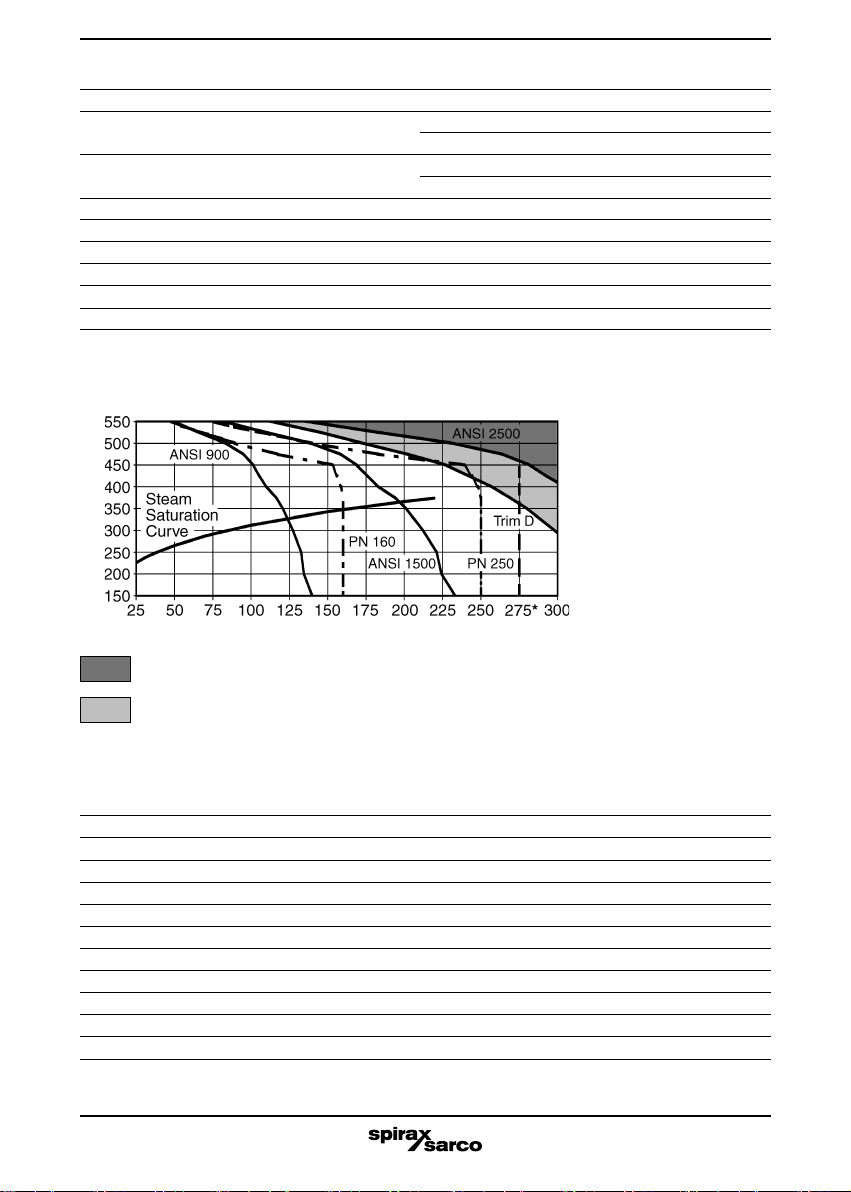
ii) Check material suitability, pressure and temperature and their maximum and minimum
values. If the maximum operating limits of the product are lower than those of the system in
which it is being fitted, or if malfunction of the product could result in a dangerous overpressure
or overtemperature occurrence, ensure a safety device is included in the system to prevent
such over-limit situations.
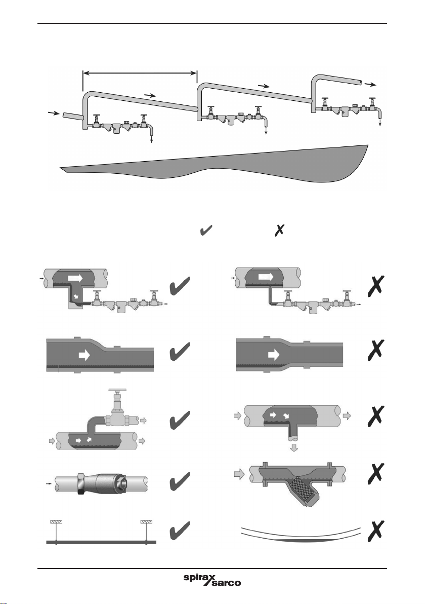
iii) Determine the correct installation situation and direction of fluid flow.
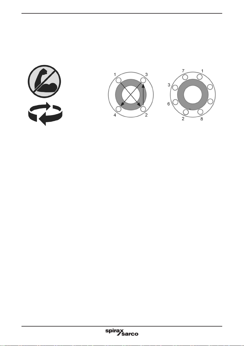
iv) Spirax Sarco products are not intended to withstand external stresses that may be induced
by any system to which they are fitted. It is the responsibility of the installer to consider these
stresses and take adequate precautions to minimise them.
v) Remove protection covers from all connections before installation.
1.2 Access
Ensure safe access and if necessary a safe working platform (suitably guarded) before attempting
to work on the product. Arrange suitable lifting gear if required.
1.3 Lighting
Ensure adequate lighting, particularly where detailed or intricate work is required.
1.4 Hazardous liquids or gases in the pipeline
Consider what is in the pipeline or what may have been in the pipeline at some previous time.
Consider: flammable materials, substances hazardous to health, extremes of temperature.
1.5 Hazardous environment around the product
Consider: explosion risk areas, lack of oxygen (e.g. tanks, pits), dangerous gases, extremes of
temperature, hot surfaces, fire hazard (e.g. during welding), excessive noise, moving machinery.
1.6 The system
Consider the effect on the complete system of the work proposed. Will any proposed action (e.g.
closing isolation valves, electrical isolation) put any other part of the system or any personnel at
risk? Dangers might include isolation of vents or protective devices or the rendering ineffective
of controls or alarms. Ensure isolation valves are turned on and off in a gradual way to avoid
system shocks.
Safe operation of these products can only be guaranteed if they are properly installed,
commissioned, used and maintained by qualified personnel (see Section 1.11 on this document)
in compliance with the operating instructions.
General installation and safety instructions for pipeline and plant construction, as well as the
proper use of tools and safety equipment must also be complied with.
1.1 Intended use
Referring to the Installation and Maintenance Instructions, name-plate and Technical Information
Sheet, check that the product is suitable for the intended use/application. These products
comply with the requirements of the European Pressure Equipment Directive 97/23/EC and
carry the mark when so required. It should be noted that product rated as ‘SEP’ are required
by the Directive not to carry the mark. The products fall within the following Pressure
Equipment Directive categories
Group 1 Group 2 Group 1 Group 2
Product Gases Gases Liquids Liquids
DT300F DN ½", ¾", 1" - *SEP - *SEP
DT300F DN 1½" - 1 - *SEP
* Products within this category are required by the Directive not to carry the mark.

3.333.5275.247
4
1.7 Pressure systems
Ensure that any pressure is isolated and safely vented to atmospheric pressure. Consider
double isolation (double block and bleed) and the locking or labelling of closed valves. Do not
assume that the system has depressurised even when the pressure gauge indicates zero.
1.8 Temperature
Allow time for temperature to normalise after isolation to avoid danger of burns.
1.9 Tools and consumables
Before starting work ensure that you have suitable tools and/or consumables available. Use
only genuine Spirax Sarco replacement parts.
1.10 Protective clothing
Consider whether you and/or others in the vicinity require any protective clothing to protect
against the hazards of, for example, chemicals, high /low temperature, radiation, noise, falling
objects, and dangers to eyes and face.
1.11 Permits to work
All work must be carried out or be supervised by a suitably competent person. Installation and
operating personnel should be trained in the correct use of the product according to the Installation
and Maintenance Instructions. Where a formal ‘permit to work’ system is in force it must be
complied with. Where there is no such system, it is recommended that a responsible person
should know what work is going on and, where necessary, arrange to have an assistant whose
primary responsibility is safety. Post ‘warning notices’ if necessary.
1.12 Handling
Manual handling of large and/or heavy products may present a risk of injury. Lifting, pushing,
pulling, carrying or supporting a load by bodily force can cause injury particularly to the back. You
are advised to assess the risks taking into account the task, the individual, the load and the
working environment and use the appropriate handling method depending on the circumstances
of the work being done.
1.13 Residual hazards
In normal use the external surface of the product may be very hot. If used at the maximum
permitted operating conditions the surface temperature of some products may reach temperatures
over 500°C. Many products are not self-draining. Take due care when dismantling or removing
the product from an installation (refer to ‘Maintenance instructions’).
1.14 Freezing
Provision must be made to protect products which are not self-draining against frost damage in
environments where they may be exposed to temperatures below freezing point.
1.15 Safety information - Product specific
See the specific details relating to product in the following ‘Maintenance’ section.
1.16 Disposal
Unless otherwise stated in the Installation and Maintenance Instructions, this product is recyclable
and no ecological hazard is anticipated with its disposal providing due care is taken.
1.17 Returning products
Customers and stockists are reminded that under EC Health, Safety and Environment Law,
when returning products to Spirax Sarco they must provide information on any hazards and the
precautions to be taken due to contamination residues or mechanical damage which may
present a health, safety or environmental risk. This information must be provided in writing
including Health and Safety data sheets relating to any substances identified as hazardous or
potentially hazardous.

3.333.5275.247 5
2. General product information
2.1. General description
The series DT300F thermodynamic steam traps are manufactured with alloy steel body and
cover; internal components are made from stainless steel. They are equipped with an internal
maintainable strainer and are suitable for use with high pressure and high temperature steam.
DT300F traps can operate on plants with back pressure up to 50% of the inlet pressure.
Standards
These steam traps comply with the requirements of the European Pressure Equipment Directive
97/23/EC and carry the mark when so required.
Certification
The product is available with material certification to EN 10204 2.2 or EN 10204 3.1.
Note: Certification and any tests must be specified at the time of order.
Available types
Four different executions with differentiated internal mechanism (type A, B, C, D) and sized in
accordance to the discharge capacity requirements.
2.2. Pipe connections and sizes
Connection types
- Socket weld ends, ANSI B16.11 SW, (standard)
- Butt weld ends, ANSI B16.25 BW, (standard)
- Screwed, ANSI B1.20.1 NPT (API), (standard)
- Flanged, UNI - DIN PN 100, 160, 250, (on demand)
- Flanged, ANSI B 16.5 class 600, 900, 1500, 2500 RF, (on demand)
Nominal sizes
- DN ½”, ¾”, 1”, 1½” (BW and flanged execution only)
- DN 15, 20, 25, 40
Dimensions / weights (approximate) in mm and kg
DN ½" ¾" 1" 1½"
Connections S Weight S Weight S Weight S Weight
Scrd / BW / SW 200 15.0 200 15.0 200 15.0 200 15.0
Flg. PN 100 / 160 295 17.0 310 18.0 320 20.2 330 23.0
Flg. PN 250 325 20.0 330 21.0 335 22.0 365 28.0
Flg. ANSI 600 320 16.8 330 17.6 340 18.6 355 23.0
Flg. ANSI 900 / 1500 337 18.4 355 20.4 363 22.2 382 26.8
Flg. ANSI 2500 363 22.2 375 23.0 395 27.0 440 40.0
S
180
220

3.333.5275.247
6
2.4 Materials
Part Material Designation
Body Alloy steel ASTM A 182 F 22
Cover Alloy steel ASTM A 182 F 22
Body gasket Stainless steel AISI 304
Studs Steel ASTM A 193 B 16
Nuts Steel ASTM A 194 g. 8
Trim set Stainless steel AISI S 400
Strainer screen Stainless steel AISI 316
Strainer cover Alloy steel ASTM A 182 F 22
Strainer gasket Armco iron
Strainer flange screws Steel ASTM A 193 B 16
2.3 Limiting conditions (ISO 6552)
Body design conditions ANSI 2500
PMA - Maximum allowable pressure DT300F/A-B-C @ 20°C 430 bar g
DT300F/D @ 20°C 365 bar g
TMA - Maximum allowable temperature DT300F/A-B-C @ 113 bar 560°C
DT300F/D @ 100 bar 560°C
Minimum allowable temperature -10°C
PMO - Maximum operating suggested pressure 275 bar g*
TMO - Maximum operating temperature 550°C
Maximum operating back pressure as percentage of upstream pressure 50%
Minimum differential pressure for satisfactory performance 15 bar g
Designed for a maximum cold hydraulic test pressure of 645 bar g
These values can be limited by the rating of the flanges installed
The product must not be used in this region
Limit imposed by trim D
Temperature °C
Pressure bar g
Pressure - temperature range

3.333.5275.247 7
2.5 Capacities
The condensate discharge capacities can be deduced by the diagram below shown.
Condensate kg/h
Differential pressure bar g
Hot water capacity
Cold water capacity

3.333.5275.247
8
Note: Before actioning any installation, observe the “General safety information” in
section 1.
Referring to the Installation and Maintenance Instructions, name-plate and Technical Information
Sheet, check that the product is suitable for the intended installation.
3.1 The preferred installation is in a horizontal pipe as shown in the illustration, with the
jutting part of the strainer beneath.
3.2 The inlet pipe should have a drop leg of at least 20 cm before the trap and continue
vertically for a further 10 cm to create a small well to collect any impurities, better still
with an exhaust valve fitted to manually blow-off the well.
3.3 The outlet pipe must be of appropriate diameter to support the considerable steam
flashing that is caused with a very high differential pressure.
3.4 With a piped discharge to recovery system, the pipe should be sized with a maximum
flash steam speed of 20 - 25 m/s.
3.5 Do not install the stop valve at less than 1-2 meters downstream from the trap.
3.6 If continuous operations are required or for easier maintenance work, a stop valve can
be installed upstream, one downstream and another in bypass (see fig. 1).
3.7 When starting up, in order to ensure better exhaust of the air and uncondensed gas and
to speed the warm up, open the bypass valve and then close it as son as the bypass line
reaches a temperature close to that of the saturated steam.
3.8 The welding of the steam trap to the pipes must conform to national and international
standards. The user must ensure that the correct welding procedure is used.
3. Installation
Fig. 1 - Process drain with discharge piped to recovery
Process
Steam main
Bypass
valve
DT300F steam trap

3.333.5275.247 9
Note: Before actioning any maintenance program observe the “General safety
information” in Section 1.
6.1. General Information
Due to the specific set-up of the trap, no special maintenance is required.
The trap operates correctly when the condensation is discharged in blasts, with a time interval
between discharges during which the trap must be perfectly sealed. Inspect and clean the
strainer ensuring that it is not blocked by any deposits or scaling, and replace if needed.
6.2. Replacing internal parts
Warning: before to undertaking any maintenance on the trap it must be isolated from
both the supply line and return line and any pressure allowed to safely normalise to the
atmosphere. The trap should then be allowed to cool.
1. Open the trap by unscrewing the 6 nuts using a 30 mm spanner.
2. Dismantle the trim set using the following spanners:
Trim set A 32 mm spanner
Trim set B 36 mm spanner
Trim set C 41 mm spanner
Trim set D 50 mm spanner
3. After cleaning all joint faces, fit the new unit and tighten with a torque of about 140 N m.
4. Clean the gasket faces and close the unit, replacing the gasket if it is damaged and tighten in
a crossed sequence.
5. To replace the strainer, unscrew the screws using a 19 mm spanner; remove the cover and
withdraw the screen and the gasket; fit the new screen and gasket; tighten the two screws
with a torque of about 50 N m.
6. Maintenance
The thermodynamic steam trap discharges condensation with a blast at a very high temperatu-
re; if the trap is to discharge to atmosphere ensure it is piped to a protected and safe place.
5. Operation
4. Commissioning
After installation or maintenance, check that the system works correctly and test all the alarms
and protections devices.
After 24 hours from the start up it is advisable to check the cover nuts tightening acting with a
torque of 100 N m.

3.333.5275.247
10
The available spare parts are indicated in the table with reference number given in the drawing.
No other parts are available as spares.
How to order spares
Always order spare parts by using the description given in the table and state the type of trap,
the internal trim set type and size of the connections.
Example: 1 Internal trim set for a DT300F/B Spirax Sarco steam trap, DN 1".
7. Spare parts
Available spares
Internal trim set 1 - 2
Body gaskets set (3 off) 2
Strainer assembly (1 off) 3 - 4
Strainer gasket set (3 off) 4

3.333.5275.247 11

3.333.5275.247 Issue 7.1 - 2013.04
Spirax-Sarco S.r.l. - Via per Cinisello, 18 - 200834 Nova Milanese (MB) - Tel.: 0362 49 17.1 - Fax: 0362 49 17 307
REPAIRS
Please contact our nearest Branch Office or Agent, or directrly Spirax Sarco S.r.l.
Via per Cinisello 18 - 20834 Nova Milanese (MB) - Tel. +39 0362 49 17.1 - Fax. +39 0362.49 17 307
LOSS OF WARRANTY
Total or partial disregard of above instructions involves loss of any right to guarantee.
Table of contents
Popular Dryer manuals by other brands

Crosley
Crosley CDG2000FW1 installation instructions

Grundig
Grundig GTN 37250GC user manual

GE
GE GTDS820GDWS Dimensions and installation information

Whirlpool
Whirlpool LDR3822D Use and care guide

Bosch
Bosch WTW8549MSN Installation and operating instructions

Panasonic
Panasonic NH-P70G2 Operating instructions & installation instructions

Frigidaire
Frigidaire FRG5711KW Guide d’utilisation et d’entretien

GE
GE DDE7209R Use and care guide

Aktobis
Aktobis WDH-35B manual

Siemens
Siemens WT4HY749DN Installation and operating instructions

Siemens
Siemens WT47W5W0 manual

American Dryer Corp.
American Dryer Corp. MLG-460 Installation & operator's manual