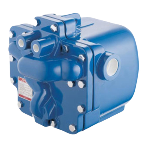
Spirax Sarco MFP14-PPU User manual

IM-P681-02 ST Issue 2 1
1. Safety information
2. General
product information
3. Single MFP14 - PPU
installation and
commissioning
4. Duplex MFP14 - PPU
installation and
commissioning
5. Triplex MFP14 - PPU
installation and
commissioning
6. Maintenance
7. Fault nding
© Copyright 2012
Printed in the UK
Triplex MFP14-PPU shown
MFP14-PPU (Vented)
Automatic Packaged Pump Units
Installation and Maintenance Instructions
IM-P681-02
ST Issue 2
6810560/2

IM-P681-02 ST Issue 2
2

IM-P681-02 ST Issue 2 3
1. Safety information
Safe operation of this product can only be guaranteed if it is properly installed,
commissioned, used and maintained by qualified personnel (see Section 1.11)
in compliance with the operating instructions. General installation and safety
instructions for pipeline and plant construction, as well as the proper use of tools
and safety equipment must also be complied with.
1.1 Intended use
Referring to the Installation and Maintenance Instructions, name-plate and
Technical Information Sheet, check that the product is suitable for the intended use /
application. The product listed below fully complies with the requirements of the
European Pressure Equipment Directive 97 / 23 / EC, and carries the mark when so
required. The product fallswithin the following Pressure Equipment Directive
categories:
Group 2 Group 2
Product Gases Liquids
MFP14-PPU DN25 2 SEP
Single, DN40 2 SEP
Duplex and DN50 2 SEP
Triplex DN80 x DN50 2 SEP
i) The product hasbeen specifically designed for use on steam, air or water/
condensate which is in Group 2 of the above mentioned Pressure Equipment
Directive. The products’ use on other fluids may be possible but, if this is
contemplated, Spirax Sarco should be contacted to confirm the suitability of
the product for the application being considered.
ii) Check material suitability, pressure and temperature and their maximum and
minimum values. If the maximum operating limits of the product are lower than
those of the system in which it is being fitted, or if malfunction of the product could
result in a dangerous overpressure or overtemperature occurrence, ensure a
safety device is included in the system to prevent such over-limit situations.
iii) Determine the correct installation situation and direction of fluid flow.
iv) Spirax Sarco products are not intended to withstand external stresses that may
be induced by any system to which they are fitted. It is the responsibility of the
installer to consider these stresses and take adequate precautions to minimise
them.
v) Remove protection covers from all connections and pretective film from all
name-plates, where appropriate, before installation on steam or other high
temperature applications.
1.2 Access
Ensure safe access and if necessary a safe working platform (suitably guarded)
before attempting to work on the product. Arrange suitable lifting gear if required.
1.3 Lighting
Ensure adequate lighting, particularly where detailed or intricate work is required.

IM-P681-02 ST Issue 2
4
1.4 Hazardous liquids or gases in the pipeline
Consider what is in the pipeline or what may have been in the pipeline at some
previous time. Consider: flammable materials, substances hazardous to health,
extremes of temperature.
1.5 Hazardous environment around the product
Consider: explosion risk areas, lack of oxygen (e.g. tanks, pits), dangerous gases,
extremes of temperature, hot surfaces, fire hazard (e.g. during welding), excessive
noise, moving machinery.
1.6 The system
Consider the effect on the complete system of the work proposed. Will any proposed
action (e.g. closing isolation valves, electrical isolation) put any other part of the
system or any personnel at risk?
Dangers might include isolation of vents or protective devices or the rendering
ineffective of controls or alarms. Ensure isolation valves are turned on and off in
a gradual way to avoid system shocks.
1.7 Pressure systems
Ensure that any pressure is isolated and safely vented to atmospheric pressure.
Consider double isolation (double block and bleed) and the locking or labelling of
closed valves. Do not assume that the system has depressurised even when the
pressure gauge indicates zero.
1.8 Temperature
Allow time for temperature to normalise after isolation to avoid danger of burns.
1.9 Tools and consumables
Before starting work ensure that you have suitable tools and/or consumables
available. Use only genuine Spirax Sarco replacement parts.
1.10 Protective clothing
Consider whether you and/or others in the vicinity require any protective clothing
to protect against the hazards of, for example, chemicals, high/low temperature,
radiation, noise, falling objects, and dangers to eyes and face.
1.11 Permits to work
All work must be carried out or be supervised by a suitably competent person.
Installation and operating personnel should be trained in the correct use of the
product according to the Installation and Maintenance Instructions.
Where a formal 'permit to work' system is in force it must be complied with. Where
there is no such system, it is recommended that a responsible person should know
what work is going on and, where necessary, arrange to have an assistant whose
primary responsibility is safety.
Post 'warning notices' if necessary.

IM-P681-02 ST Issue 2 5
1.12 Handling
Manual handling of large and/or heavy products may present a risk of injury. Lifting,
pushing, pulling, carrying or supporting a load by bodily force can cause injury
particularly to the back. You are advised to assess the risks taking into account the
task, the individual, the load and the working environment and use the appropriate
handling method depending on the circumstances of the work being done.
1.13 Residual hazards
In normal use the external surface of the product may be very hot. These products
are not self-draining. Take due care when dismantling or removing the product from
an installation (refer to 'Maintenance instructions').
1.14 Freezing
Provision must be made to protect products which are not self-draining against
frost damage in environments where they may be exposed to temperatures below
freezing point.
1.15 Disposal
Unless otherwise stated in the Installation and Maintenance Instructions, this
product is recyclable and no ecological hazard is anticipated with its disposal
providing due care is taken.
1.16 Returning products
Customers and stockists are reminded that under EC Health, Safety and
Environment Law, when returning products to Spirax Sarco they must provide
information on any hazards and the precautions to be taken due to contamination
residues or mechanical damage which may present a health, safety or
environmental risk. This information must be provided in writing including
Health and Safety data sheets relating to any substances identified as hazardous
or potentially hazardous.

IM-P681-02 ST Issue 2
6
2. General product information
2.1 Description
The Spirax Sarco MFP14-PPU vented automatic pump packaged units are plug-in systems
specifically designed to collect and pump hot condensate; commonly returned for use as
boiler feedwater.
The MFP14-PPU is available with either single, duplex or triplex pumps, mounted on a single
base plate, that can be used for duty only or duty / stand-by applications.
Operated by steam, the MFP14-PPU can be tailored to suit a wide range of condensate
handling applications.
The standard pump is manufactured from SG iron, although cast steel and stainless steel
versions are available on request.
Please note: Versions suitable for use with compressed air as the motive power and or other
combinations are available as bespoke items. For further details contact your local Spirax
Sarco office or representative.
Optional extras
A pump insulation jacket is available at extra cost - see TI-P136-07.
Standards
The MFP14-PPU fully complies with the requirements of the European Pressure Equipment
Directive 97 /23 / EC and carries the mark when so required.
All welding is in accordance with the requirements of the European Pressure Equipment
Directive 97 / 23 / EC (PED).
Certification
This product is available with a declaration of conformity. For other certification requirements
contact Spirax Sarco. Note: All certification / inspection requirements must be stated at
the time of order placement. Retrospective certification / inspection may not be possible.
Note: For additional product data see Technical Information sheet TI-P680-03.
2.2 Capacities
Unit size
Approximate maximum capacities kg / h (with 4M lift).
See separate TI sheet for full capacity details.
Single
MFP14-PPU
Duplex
MFP14-PPU
Triplex
MFP14-PPU
DN25
(1") 1 300
DN40
(1½") 2000 4000
DN50
(2") 4000 8000
DN80 x DN50
(3" x 2") 6000 12 000 18000

IM-P681-02 ST Issue 2 7
2.3 Pressure / temperature limits
Body design condition PN16
Maximum receiver operating pressure 0.5 bar g
MFP14 13.8 bar g
Maximum motive inlet pressure MFP14S 13.8 bar g
(steam) MFP14SS 10.96 bar g
MFP14 16 bar g @ 120°C
PMA Maximum allowable pressure MFP14S 16 bar g @120°C
MFP14SS 16 bar g @ 93°C
MFP14 300°C @ 12.8 bar g
TMA Maximum allowable temperature MFP14S 300°C @ 10.8 bar g
MFP14SS 300°C @ 9.3 bar g
Minimum allowable temperature 0°C
MFP14 13.8 bar g @ 198°C
PMO Maximum operating pressure MFP14S 13.8 bar g @ 198°C
MFP14SS 10.96 bar g @ 188°C
MFP14 198°C @ 13.8 bar g
TMO Maximum operating temperature MFP14S 198°C @ 13.8 bar g
MFP14SS 188°C @ 10.96 bar g
Minimum operating temperature 0°C
Note: For lower operating temperatures consult Spirax Sarco
Designed for a maximum cold hydraulic test pressure of: 24 bar g

IM-P681-02 ST Issue 2
8
2.4 Sizes and pipe connections
Single MFP14-PPU
For further information regarding installation, location and commissioning
see Section 3.
Unit size
Pipe
connection
V
(Con out)
W
(Motive)
X
(Overflow)
Y
(Vent)
Z
(Inlet)
DN25
(1")
PN16 DN25 DN15 DN50 PN16 DN80 DN40
ASME 150 1"
ASME 150
½"
ASME 150
2"
ASME 150
3"
ASME 150
1½"
ASME 150
DN40
(1½")
PN16 DN40 DN15 DN50 PN16 DN100 DN40
ASME 150 1½"
ASME 150
½"
ASME 150
2"
ASME 150
4"
ASME 150
1½"
ASME 150
DN50
(2")
PN16 DN50 DN15 DN50 PN16 DN150 DN65
ASME 150 2"
ASME 150
½"
ASME 150
2"
ASME 150
6"
ASME 150
2½"
ASME 150
DN80 x DN50
(3" x 2")
PN16 DN50 DN15 DN50 PN16 DN150 DN65
ASME 150 2"
ASME 150
½"
ASME 150
2"
ASME 150
6"
ASME 150
2½"
ASME 150
Duplex MFP14-PPU
For further information regarding installation, location and commissioning
see Section 4.
Unit size
Pipe
connection
V
(Con out)
W
(Motive)
X
(Overflow)
Y
(Vent)
Z
(Inlet)
DN40
(1½")
PN16 DN40 DN15 DN50 DN150 DN50
ASME 150 1½"
ASME 150
½"
ASME 150
2"
ASME 150
6"
ASME 150
2"
ASME 150
DN50
(2")
PN16 DN50 DN15 DN50 DN200 DN65
ASME 150 2"
ASME 150
½"
ASME 150
2"
ASME 150
8"
ASME 150
2½"
ASME 150
DN80 x DN50
(3" x 2")
PN16 DN50 DN15 DN50 DN200 DN80
ASME 150 2"
ASME 150
½"
ASME 150
2"
ASME 150
8"
ASME 150
3"
ASME 150
Triplex MFP14-PPU
For further information regarding installation, location and commissioning
see Section 5.
Unit size
Pipe
connection
V
(Con out)
W
(Motive)
X
(Overflow)
Y
(Vent)
Z
(Inlet)
DN80 x DN50
(3" x 2")
PN16 DN50 DN25 DN50 DN250 DN80
ASME 150 2"
ASME 150
1"
ASME 150
2"
ASME 150
10"
ASME 150
3"
ASME 150

IM-P681-02 ST Issue 2 9
Fig. 1
Single MFP14-PPU
Fig. 2
Duplex MFP14-PPU
Fig. 3
Triplex MFP14-PPU
YZZ
X
W
VYZZ
X
W
Z
Z
Y
X
V
W
V
V V

IM-P681-02 ST Issue 2
10
3. Single MFP14 - PPU
3.1 Installation
Safety notes:
Before actioning any installation observe the 'Safety information' in Section 1.
Important note: Please acknowledge the safe lifting points indicated on Figure 5.
3.2 Location
The MFP14-PPU should be located in a suitable position e.g. against a wall where the vent can
be easily piped to atmosphere. It is recommended that reasonable clearance is maintained
around the unit for ease of access.
1. Note: The receiver vent (Y) must be piped unreduced and unrestricted to a safe atmospheric
discharge point. The line should be vertical, if possible. If horizontal runs must be used, the
line should be pitched so that it is self draining to the receiver. A suitably sized vent head should
be fitted to the top of the vent pipe to ensure safe discharge of flash steam. Refer to Table 1 below for
the recommended receiver vent pipe sizing.
Table 1. Recommended receiver vent pipe sizing
PPU size Reciever vent diameter
DN25 1" 80 mm 3"
DN40 1½" 100 mm 4"
DN50 2" 150 mm 6"
DN80 x DN50 3" x 2" 150 mm 6"
The recommended receiver vent size is based on:
- A maximum flash velocity in the receiver of 20 m / s.
- A maximum vent velocity of of 30 m / s.
- A maximum unrestricted vent pipe length of 10 m.
- A maximum condensate inlet pressure (discharge from steam traps) of 10 bar g.
2. Connect the condensate outlet (V) of the MFP14-PPU to the condensate return line.
3. Connect the condensate inlets (Z) to the process / equipment being drained.
4. Connect a 'U' bend water seal to the overflow point (X) and ensure that it is connected to a
safe discharge point. Ensure a suitable amount of water is filled into the 'U' bend before
commissioning the PPU. The 'U' bend water seal, during normal operation, is self-filling
and prevents 'flash steam' discharging from the overflow. It is recommended the 'U' bend
is at least 305 mm (12") deep.
Always connect the overflow
to a safe discharge point,
remembering that any
condensate that discharges
may be hot. Care should
be taken to ensure that
hot condensate being
discharged to drain does not
infringe local temperature or
environmental regulations.
5. Connect the operating
medium (steam) to the motive
supply inlet (W).
6. The MFP14-PPU is now
ready to be commissioned
(see Section 3.3). Fig. 4
Connection to atmospheric vent line
'U' bend water seal
overow point
Connect to a safe
discharge point
Recommended
305 mm (12")
minimum
Y
X

IM-P681-02 ST Issue 2 11
3.3 Commissioning
1. Slowly open the steam motive supply isolating valve (item 7) to provide pressure
to the MFP14-PPU. Check that the motive drain trap (item 9where fitted) is operational.
2. Open any isolation valves between the process being drained and the MFP14-PPU at
point (Z).
3. Open the inlet isolation valve (item 5) and the condensate outlet isolation valve (item 5)
in the condensate return line (point V).
4. Condensate should now start to flow into the main receiver (item 1) and into the pump (item 3)
when the plant is operational.
5. Check all flanged/screwed connections for any leakage.
6. Observe operation for any abnormalities. The pump (item 3) should cycle periodically
(minimum cycle time is 8 seconds) with an audible exhaust at the end of the pumping cycle.
This can be used to monitor the operation of the unit and meter the volume of condensate
pumped. If any irregularities are observed, recheck Sections 3.1 and 3.2 for proper
arrangement. Consult Spirax Sarco if necessary.
7. The system is now operational.
1
5
3
7
5
8 + 9
6
Y
ZZ
X
W
V
Fig. 5
The only safe
lifting points

IM-P681-02 ST Issue 2
12
3.4 Materials
No Part Material
1Receiver Mild steel
2Base plate and frame Mild steel
3 MFP14 pump SG iron
4DCV10 check valve Stainless steel
5BSA2T isolation valve SG iron
6Fig 37 strainer SG iron
7M10S2 RB ball valve straight handle Carbon steel
8PC10 Quick-fit connector Stainless steel
9 UTD30L thermodynamic steam trap Stainless steel
10 Steam inlet drain trap flexible hose Mild steel / stainless steel
11 Exhaust flexible hose Mild steel / stainless steel
12 Pipework Mild steel
Spare parts
See individual product TI
for available ancillary spares
1
5
2
4
3
7
5
4
8 + 9
6
6
11 10
12
Y
ZZ
X
W
V
Fig. 6
The only safe
lifting points

IM-P681-02 ST Issue 2 13
4. Duplex MFP14 - PPU
4.1 Installation
Safety notes:
Before actioning any installation observe the 'Safety information' in Section 1.
Important note: Please acknowledge the safe lifting points indicated on Figure 8.
4.2 Location
The MFP14-PPU should be located in a suitable position e.g. against a wall where the vent can
be easily piped to atmosphere. It is recommended that reasonable clearance is maintained
around the unit for ease of access.
1. Note: The receiver vent (Y) must be piped unreduced and unrestricted to a safe atmospheric
discharge point. The line should be vertical, if possible. If horizontal runs must be used, the
line should be pitched so that it is self draining to the receiver. A suitably sized vent head should
be fitted to the top of the vent pipe to ensure safe discharge of flash steam. Refer to Table 1 below for
the recommended receiver vent pipe sizing.
Table 1. Recommended receiver vent pipe sizing
PPU size Reciever vent diameter
DN40 1½" 150 mm 6"
DN50 2" 200 mm 8"
DN80 x DN50 3" x 2" 200 mm 8"
The recommended receiver vent size is based on:
- A maximum flash velocity in the receiver of 20 m / s.
- A maximum vent velocity of of 30 m / s.
- A maximum unrestricted vent pipe length of 10 m.
- A maximum condensate inlet pressure (discharge from steam traps) of 10 bar g.
2. Connect the condensate outlets (V) of the MFP14-PPU to the condensate return line -
See Figure 8.
3. Connect the condensate inlets (Z)to the process / equipment being drained.
4. Connect a 'U' bend water seal to the overflow point (X)and ensure that it is connected to a
safe discharge point. Ensure a suitable amount of water is filled into the 'U' bend before
commissioning the PPU. The 'U' bend water seal, during normal operation, is self-filling
and prevents 'flash steam' discharging from the overflow. It is recommended the 'U' bend
is at least 305 mm (12") deep. Always connect the overflow to a safe discharge point.
5. Connect the operating medium
(steam) to the motive supply
inlet (W).
6. The MFP14-PPU is now
ready to be commissioned
(see Section 4.3).
Fig. 7
Connection to atmospheric vent line
'U' bend water seal
overow point
Connect to a safe
discharge point
Recommended
305 mm (12")
minimum
Y
X

IM-P681-02 ST Issue 2
14
4.3 Commissioning
1. Slowly open the steam motive supply and exhaust isolating valves (item 7) to provide
pressure to the MFP14-PPU. Check that the motive trap (item 9where fitted) is operational.
2. Open any isolation valves between the process being drained and the MFP14-PPU at
points (Z).
3. Open the inlet isolation valve (item 5) and the condensate outlet isolation valve (item 5)
in the condensate return line (point V).
4. Condensate should now start to flow into the main receiver (item 1) and into the pump (item 3)
when the plant is operational.
5. Check all flanged/screwed connections for any leakage.
6. Observe operation for any abnormalities. The pump (item 3) should cycle periodically
(minimum cycle time is 8 seconds) with an audible exhaust at the end of the pumping cycle.
This can be used to monitor the operation of the unit and meter the volume of condensate
pumped. If any irregularities are observed, recheck Sections 4.1 and 4.2 for proper
arrangement. Consult Spirax Sarco if necessary.
7. The system is now operational.

IM-P681-02 ST Issue 2 15
4.4 Materials
No Part Material
1Receiver Mild steel
2Base plate and frame Mild steel
3MFP14 pump SG iron
4DCV10 check valve Stainless steel
5BSA2T Isolation valve SG iron
6Fig 37 strainer SG iron
7M10S2 RB ball valve oval / straight handles Carbon steel
8PC10 Quick-fit connector Stainless steel
9UTD30L thermodynamic steam trap Stainless steel
10 Steam inlet drain trap flexible hose Mild steel / stainless steel
11 Exhaust flexible hose Mild steel / stainless steel
12 Pipework Mild steel
13 DCV41 check valve Stainless steel
1
2
5
7
7
5
5
6
445
3
3
8 + 9
6
Spare parts
See individual product TI
for available ancillary spares
12 12
13
13
11
11
6
7
12
12
7
10
7
Y
Z
Z
X
W
V
V
Safe lifting point
Safe lifting point
Fig. 8

IM-P681-02 ST Issue 2
16
5. Triplex MFP14 - PPU
5.1 Installation
Safety notes:
Before actioning any installation observe the 'Safety information' in Section 1.
Important note: Please acknowledge the safe lifting points indicated on Figure 9.
5.2 Location
The MFP14-PPU should be located in a suitable position e.g. against a wall where the vent can
be easily piped to atmosphere. It is recommended that reasonable clearance is maintained
around the unit for ease of access.
1. Note: The receiver vent (Y) must be piped unreduced and unrestricted to a safe atmospheric
discharge point. The line should be vertical, if possible. If horizontal runs must be used, the
line should be pitched so that it is self draining to the receiver A suitably sized vent head should
be fitted to the top of the vent pipe to ensure safe discharge of flash steam. Refer
to Table 1 below for the recommended receiver vent pipe sizing.
Table 1. Recommended receiver vent pipe sizing
PPU size Reciever vent diameter
DN80 x DN50 3" x 2" 250 mm 10"
The recommended receiver vent size is based on:
- A maximum flash velocity in the receiver of 20 m / s.
- A maximum vent velocity of of 30 m / s.
- A maximum unrestricted vent pipe length of 10 m.
- A maximum condensate inlet pressure (discharge from steam traps) of 10 bar g.
2. Connect the condensate outlets (V) of the MFP14-PPU to the condensate return line -
See Figure 9.
3. Connect the condensate inlets (Z) to the process / equipment being drained.
4. Connect a 'U' bend water seal to the overflow point (X) and ensure that it is connected to a
safe discharge point. Ensure a suitable amount of water is filled into the 'U' bend before
commissioning the PPU. The 'U' bend water seal, during normal operation, is self-filling
and prevents 'flash steam' discharging from the overflow. It is recommended the 'U' bend
is at least 305 mm (12") deep. Always connect the overflow to a safe discharge point.
5. Connect the operating medium (steam) to the motive supply inlet (W).
6. The MFP14-PPU is now ready to be commissioned (see Section 5.3).
5.3 Commissioning
1. Slowly open the steam motive supply and exhaust isolating valves (item 7) to provide
pressure to the MFP14-PPU. Check that the motive trap (item 9where fitted) is operational.
2. Open any isolation valves between the process being drained and the MFP14-PPU at
points (Z).
3. Open the inlet isolation valve (item 5) and the condensate outlet isolation valve (item 5)
in the condensate return line (point V).
4. Condensate should now start to flow into the main receiver (item 1) and into the pump (item 10)
when the plant is operational.
5. Check all flanged/screwed connections for any leakage.
6. Observe operation for any abnormalities. The pump (item 3) should cycle periodically
(minimum cycle time is 8 seconds) with an audible exhaust at the end of the pumping cycle.
This can be used to monitor the operation of the unit and meter the volume of condensate
pumped. If any irregularities are observed, recheck Sections 5.1 and 5.2 for proper
arrangement. Consult Spirax Sarco if necessary.
7. The system is now operational.

IM-P681-02 ST Issue 2 17
5.4 Materials
No Part Material
1Receiver Mild steel
2Base plate and frame Mild steel
3MFP14 pump SG iron
4DCV10 check valve Stainless steel
5BSA2T isolation valve SG iron
6Fig 37 strainer SG iron
7M10S2 RB ball valve oval / straight handles Carbon steel
8PC10 quick-fit connector Stainless steel
9UTD30L thermodynamic steam trap Stainless steel
10 Steam Inlet flexible hose Mild steel / stainless steel
11 Exhaust flexible hose Mild steel / stainless steel
12 Pipework Mild steel
13 DCV41 check valve Stainless steel
1
5
5
5
2 6
4
4
5
5
5
3
3
3
8+9
7
7
7
Spare parts
See individual product TI
for available ancillary spares
13
13
13
12
12
12
7
7
7
67
11
11
11
10
Safe lifting point
Safe lifting point
Fig. 9
YZ
Z
X
W
V
V
V

IM-P681-02 ST Issue 2
18
6. Maintenance
Mechanism inspection and repair
Safety notes:
Before actioning any maintenance programme observe the 'safety information' in
Section 1.
Always use suitable lifting gear and that the correct lifting points are adhered to (See
Figures 6, 8, 9 and 10). Ensure the MFP14-PPU is safely secured.
When dismantling the pump, care should be taken to prevent personal injury from the
strong snap mechanism.
Always handle with care.
For full maintenance instructions, on each component of the PPU, refer to the relevant
product specific IMI supplied with the unit.
Spare parts
See the product specific TI for spares availability for each of the ancillary units that are used
to make the MFP14-PPU.
Safe lifting point
Safe lifting point
Fig. 10 Triplex MFP14-PPU shown
YZ
Z
X
W
V
V
V

IM-P681-02 ST Issue 2 19
7. Fault finding
Caution
Installation and troubleshooting should be performed by qualified personnel.
Before disconnecting any connections to the MFP14-PPU, every effort should be made
to ensure that any internal pressure has been relieved and that the motive supply line
is isolated to prevent inadvertent discharge of the pump. Verify that all hot parts have
cooled to prevent risk of injury from burns.
Always wear the appropriate safety clothing.
Quick reference trouble-shooting guide
Symptom Cause Check and cure
MFP14-PPU
fails to
operate.
Motive supply valve (item 7)
closed.
Open valves to supply motive
pressure to pump.
Condensate inlet valve
(item 5) closed.
Open all valves, including those
fitted to points (Y) and (Z) to allow
condensate to reach pump.
Condensate discharge
valve (item 5) closed.
Open all valves to allow freedischarge
from pump to condensate return line.
Motive pressure
insufficient to overcome
backpressure.
Check motive pressure and static
backpressure. Ensure motive
pressure is higher than the static
backpressure to give a differential
pressure between 2 and 4 bar g.
Restricted vent. Ensure that vent line is unrestricted
and self draining to the receiver.
Blocked condensate inlet or
motive supply strainer.
Remove screen from item 6and clean
or replace.
'U' bend water
seal is broken
and flash
steam
is discharging.
'U' bend water seal empty.
Re-prime 'U' bend with water, see
Section 3.
If flash steam discharges again from
point Xthis could indicate a blocked
vent line (Y). (Observe Safety note.)
Receiver pressurised
above 0.03 bar (0.4 psi).
Verify vent line is open and
unrestricted.
Large amount
of flash steam
vent line (Y).
Motive steam trap failed open
(steam operated versions only).
Inspect - repair or replace as
necessary.
Motive inlet valve and exhaust
valve of the pump (item 3) is
leaking.
Inspect pump (observe safety note)
repair or replace motive inlet and
exhaust valves as necessary.
Fig. 10 Triplex MFP14-PPU shown

IM-P681-02 ST Issue 2
20
Table of contents
Other Spirax Sarco Water Pump manuals
Popular Water Pump manuals by other brands

SKF
SKF Lincoln HTL 201 Assembly instructions

Jula
Jula 731-075 operating instructions

Silicon Solar
Silicon Solar AQUAJET-CUSTOM-KIT-24V-V2 user manual

Tsurumi Pump
Tsurumi Pump KTD Series Operation manual

fluidra
fluidra Rainbow Astralpool eCombi EE2 Installation and operating instructions

Titan
Titan 0509009 owner's manual

Watson-Marlow
Watson-Marlow 501RLA user manual

Bijur Delimon
Bijur Delimon FZ-B operating instructions

Gude
Gude MP 120/5A 24 LT Translation of the original instructions

Beckett
Beckett G325A6 instructions

Pfeiffer Vacuum
Pfeiffer Vacuum TPH 1600 operating instructions

BLACKMER
BLACKMER X1220A Installation, operation and maintenance instructions