IM-P681-07 CMGT Issue 2
6
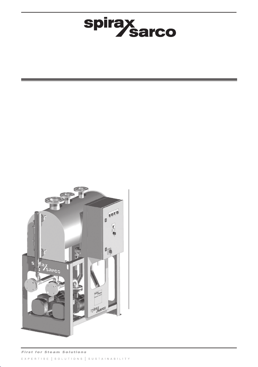
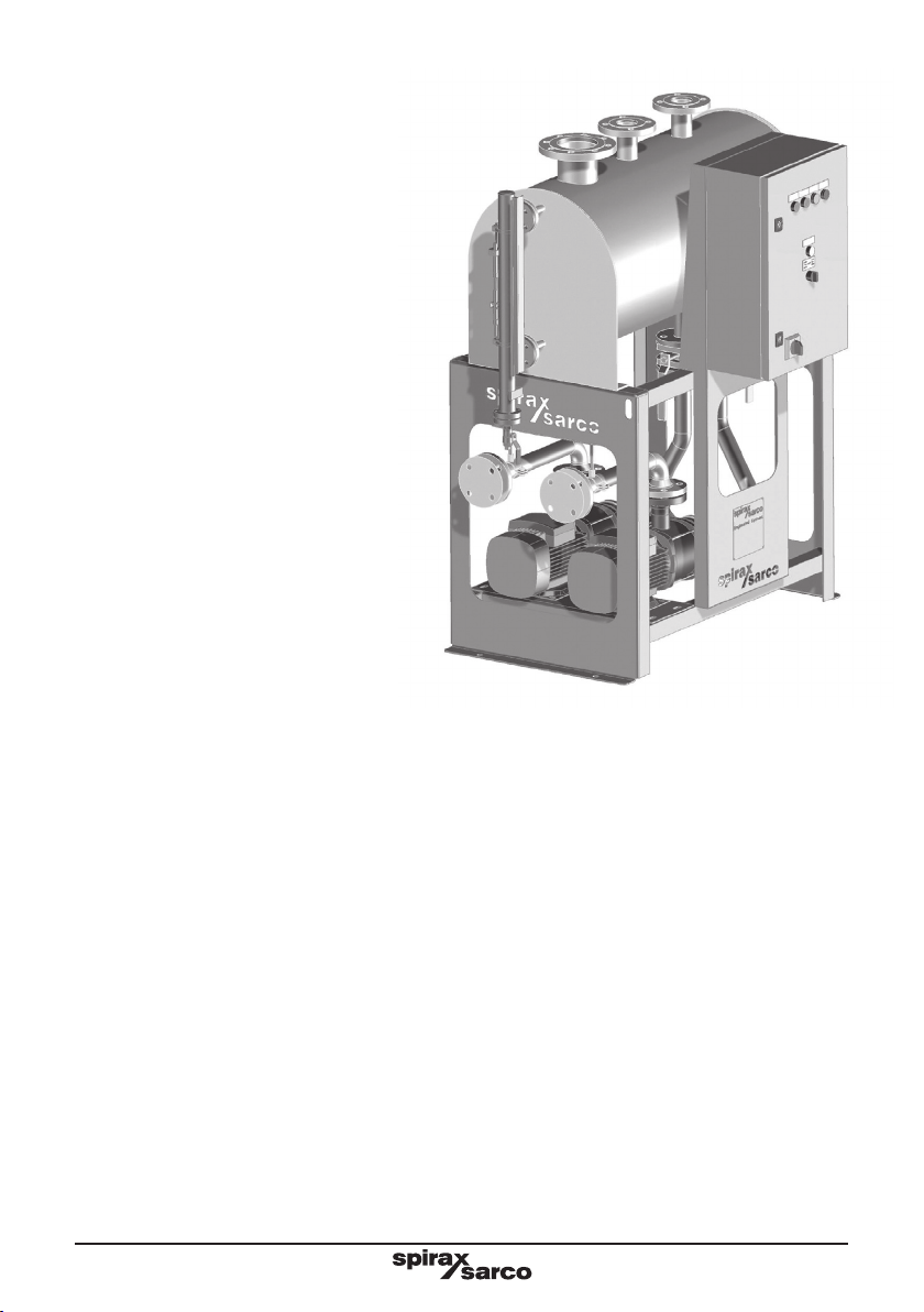
2.1 Description
The Spirax Sarco CRU 200 and 500 series condensate recovery units with fixed speed pumps are designed
to handle hot flashing condensate entering the receiver (up to 98 °C) which is commonly returned for use
as boiler feedwater.
The standard range can handle quantities up to 20 m3/hr, duty/assist with varying pump delivery heads.
For higher duties please contact Spirax Sarco.
The package comprises - receiver, frame, pumps, valves, level controls and pre-wired control panel.
Note:
1. System head regulation valves are not supplied as part on the unit, but it is recommended they are
incorporated into the discharge pipe work.
2. This unit is not suitable for outdoor use, please consult Spirax Sarco for a bespoke solution.
3. This unit is not designed to accept nozzle loads from connecting pipework.
Equipment function
Spirax Sarco CRU 200 and 500 series condensate recovery units are supplied with two pump sets arranged
to provide duty/assist control. The units are designed for fully automatic operation. Standard control features
incorporate; condensate level pump control, controls enclosure, incoming electrical supply door-interlocked
isolator switch, 'Power On' indicator lamp, 'Pump Running' and 'Pump Tripped' indicator lamps and a pump
selector switch with automatic changeover facility. Volt-free alarm terminals are provided for 'Pump Tripped'
and for 'High Condensate' alarm.
Condensate level pump control is by means of Spirax Sarco Colima Viscorol level indicators and SPDT level
controls which provide on/off duty/assist operation.
The units are controlled by high and low condensate level pump control switches but additionally have the
special duty/assist level control feature to provide for automatic operation of both the 'duty pump' plus the
'assist pump' if that operational requirement arises. If a condition occurs which enables operation of the
assist pump, the corresponding 'Pump Running' lamp will indicate that status, clearing automatically when
the condensate level falls and the pumps stops at 'Low' condensate level.
The units also incorporate duty cycle automatic changeover, the 'duty' and 'stand-by' pump operation
alternating at the end of each condensate collection vessel emptying cycle. Additionally, a 3-position pump
selector switch is incorporated to allow for selection of automatic pump changeover or single pump operation
of either pump, 'Automatic' being the usual mode selected for normal operating conditions.
An independent 'High Condensate' alarm facility (optional) is enabled at a condensate level above that for
the standard high condensate, {pump(s) on} switching levels, the alarm condition and signal being cleared
automatically when the condensate level falls to the normal operating high level. The alarm facility is be
provided with both visual (indicator lamp) and volt-free terminals.
Receiver
Receivers are manufactured from 304 stainless steel. They are fitted with an adequately sized vent, overflow
and inlet connections flanged to PN16. Vessels are leak tested. A water level gauge is fitted as standard,
with integrated level control and high alarm.
Frame
The frames are manufactured from carbon steel powder coated (black) or 304 stainless steel.
2. General product information