Spirax Sarco APT10-2 User manual

IM-P612-18 ST Issue 3 1
APT10-2
Automatic Pump Trap
Installation and Maintenance Instructions
IM-P612-18
ST Issue 3
6120050/3
Printed in the UK © Copyright 2003
1. General
safety information
2. Product information
3. Installation
• Closed loop steam systems only
4. Commissioning
5. Operation
6. Maintenance
7. Replacementofspares(1):
• Cover gasket
• Inlet swing check valve
• Spring and actuator arm
• Float
8. Replacementofspares(2):
• Trap and outlet check valve
mechanism
• Steam inlet / exhaust valves
and seats
9. Fault finding guide

IM-P612-18 ST Issue 3
2

IM-P612-18 ST Issue 3 3
1. General safety information
Safe operation of these units can only be guaranteed if they are properly installed,
commissioned and maintained by a qualified person in compliance with the operating
instructions.Allworkmustbecarriedoutorbesupervisedbyasuitablycompetentperson.
Installation and operating personnel should be trained in the correct use of the product
according to the Installation and Maintenance Instructions.
Where a formal 'permit to work' system is in force it must be complied with. Where there is
no such system, it is recommended that a responsible person should know what work is
going on and, where necessary, arrange to have an assistant whose primary responsibilty
is safety.
Post 'warning notices' if necessary.
General installation and safety instructions for pipeline and plant construction, as well as
the proper use of tools and safety equipment must also be complied with.
Isolation
Consider whether closing isolating valves will put any other part of the system or
personnel at risk. Dangers might include: isolation of vents, protective devices or
alarms. Ensure isolation valves are turned off in a gradual way to avoid system shocks.
Pressure
Before attempting any maintenance consider what is or may have been in the pipeline.
Ensure that any pressure is isolated and safety vented to atmospheric pressure before
attempting to maintain the product, this is easily achieved by fitting Spirax Sarco
depressurisationvalvestypeDV(seeseparateliteraturefordetails).Donotassumethatthe
system is depressurised even when a pressure gauge indicates zero.
Temperature
Allow time for temperature to normalise after isolation to avoid the danger of burns and
consider whether protective clothing (including safety glasses) is required.
Disposal
These products are recyclable. No ecological hazard is anticipated with the disposal
of these products providing due care is taken.

IM-P612-18 ST Issue 3
4
2. Product information
Description
TheSpiraxSarcoautomaticpumptrapisadisplacementreceiverpressureratedtoPN10.Theunit
iscapableofautomaticallytrappingorpumping,dependingonlineconditions.Theunitisoperated
by steam and is used to remove condensate from process and heating plant under all pressure
conditions including vacuum.
Sizes and pipe connections
Size DN20 x DN20
Fluid connections
Inlet Outlet Motive/Exhaust
DN20 (¾") DN20 (¾") DN15 (½")
BSP - BS 21 parallel BSP
NPT NPT
Limiting conditions
Body design conditions PN10
Maximum motive inlet pressure 2.0 bar g (29 psi g)
Maximum operating pressure 2.0 bar g (29 psi g)
Maximum back pressure 1.9 bar g (27 psi g)
Maximum operating temperature 133°C (271°F)
Minimum operating temperature -10°C(14°F)
Designed for a maximum cold hydraulic test pressure of: 15.0 bar g (217 psi g)
Minimum installation head (from base of pump) 0.2 m (8")
Recommended minimum installation head (from base of pump) 0.3 m (12")
Technical specification - Nominal capacities
For full capacity details for a specific application consult Spirax Sarco.
To accurately size the pump trap, the following data is required.
1. Installationheadavailable,fromthebaseofthepumptraptothecentrelineoftheheatexchanger/
process condensate outlet (m). If the outlet is mounted vertically, then this should be from the
base of the pump to the face of the outlet.
2. Motive steam pressure available to power the pump trap (bar g).
3. Total back pressure in the condensate return system (barg). See note below.
4. Heat exchanger full load operating pressure (bar g).
5. Heat exchanger maximum steam load (kg/h).
6. Minimum temperature of secondary fluid. (°C).
7. Maximum controlled temperature of secondary fluid (°C).
Size DN20 x DN20
Pump discharge/cycle 2.1 litres
1 metre installation head Maximum trapping capacity 735 kg/h
At: 2.0 bar g (29 psi g) motive
0.5 bar g (7 psi g) total back pressure Maximum pumping capacity 405 kg/h
Note: Total lift or back pressure BP (static head plus pressure head in the return system) must be
below the motive fluid inlet pressure to allow pump capacity to be achieved.
BP (back pressure) = (H x 0.0981) + (P) + (Pf)
Height(H)in metresx 0.0981pluspressure (P)barg inthe returnline, plus downstream piping
friction pressure drop (Pf) in bar.
(Pfcanbeignoredifthedownstreampipeworkisless than100metresto anon-floodedcondensate
returnandhasbeensizedtotakeintoaccounttheeffectofflashsteamattheheatexchanger'sfull
load operating conditions.)

IM-P612-18 ST Issue 3 5
Fig. 1
Fig. 2
Dimensions / weights (approximate) in mm and kg
Size A B C D E F G H I Weight
DN20 x DN20 187 23 223 266 273 194 57 225 171 14
I
B
D
E
H
G
C
Motive
steam
supply Exhaust
A
F
OUT
IN

IM-P612-18 ST Issue 3
6
Materials
No. Part Material
1Cover SG iron DIN 1693 GGG 40.3 / ASTM A395
2Cover gasket Graphite laminated with stainless steel insert
3Body SG iron DIN 1693 GGG 40.3 / ASTM A395
4Cover bolts Stainless steel BS EN ISO 3506 Gr. A2 70
5Pump trap lever Stainless steel BS 1449 304 S15
6Float Stainless steel BS 1449 304 S16
7Pivot shaft Stainless steel BS 970 431 S29 / ASTM A276 431
8Washer Stainless steel BS 1449 316
9Trap housing Stainless steel BS 970 431 S29 / ASTM A276 431
10 Ball ASTM A276 440 B
11 Seat (inlet check valve) Stainless steel AISI 420
12 Flap (inlet check valve) Stainless steel BS 3146 ANC 4B
13 Pump mechanism Stainless steel BS 3146 ANC 4B
bracket
14 Spring (pump) Stainless steel BS 2056 302 S26 Gr. 2
15 Split pin Stainless steel BS 1574
16 Exhaust seat Stainless steel BS 970 431S29 / ASTM A276 431
17 Inlet valve and seat assembly Stainless steel
18 Exhaust valve Stainless steel BS 3146 ANC 2
19 Valve seat gasket Stainless steel BS 1449 409 S19
20 Pump mechanism bolt Stainless steel BS EN ISO 3506 Gr. A2-70
21 Float bolt Stainless steel BS EN ISO 3506 Gr. A2-70
22 Trap 1st stage valve Stainless steel BS 970 431 S29 / ASTM A276 431
23 Trap gasket Stainless steel BS 1449 409 S19
24 Actuator arm Stainless steel BS 3146 ANC 2
25 Name-plate Stainless steel BS 1449 304 S16
26 Drain plug Stainless steel DIN 17440 1.4571
Disposal
There are no hazardous materials used in the construction of this product.
Any unwanted material should be recycled or disposed of in an environmentally friendly manner.

IM-P612-18 ST Issue 3 7
Fig. 3
3
12
4
6
21
12
17
13
20
14 11
24
18
5
25
26
16
Trap and
outlet check valve
mechanism
9
8
22
23
10
7
15
19

IM-P612-18 ST Issue 3
8
Important - safety note
Before any installation or maintenance procedure, always ensure that all steam or
condensate lines are isolated.
Ensure any residual internal pressure in the product or connecting lines is carefully
relieved. Also ensure any hot parts have cooled to prevent risk of injury from burns. Always
wear appropriate safety clothing before carrying out any installation or maintenance work.
Always use suitable lifting gear and ensure the product is safely secured.
3.1 Inlet piping
To prevent condensate backing up into the equipment being drained, it is recommended that the
inlet pipework is sufficiently sized to accumulate condensate during the pump’s discharge cycle.
Generally a length and diameter of pipe to accommodate 2 litres of condensate will be sufficient.
Itisrecommendedthiscondensatereservoirissituatedatleast1pipediameterbelowtheprocess
outlet but as high as possible above the APT10-2 inlet. It is essential that a Spirax Sarco Y-type
strainer with a maximum 0.8 mm perforation screen size is fitted at the condensate inlet of the
APT10-2, as shown in Fig. 5.
3.2 Recommended installation head
An installation head of at least 0.3 m (12 ins) from the base of the unit is recommended. Minimum
0.2m(8ins)withreducedcapacity.Note:Duringcoldstart-upconditions,itispossibleforhydraulic
pulsingoftheinletcheckvalvetooccur.Itisadvisableinthiscasetoinstallathrottlingisolationvalve
to reduce the filling pressure.
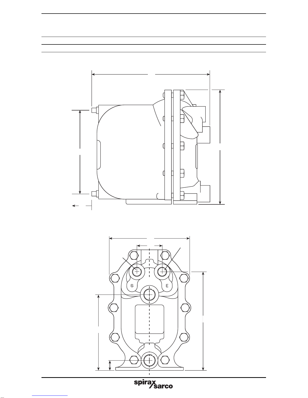
3.3 Connections (refer to installation diagram Fig. 4 opposite)
The APT10-2 has four connection ports. The DN20 (¾") port marked (IN) should be connected to
theoutletoftheequipmentbeingdrained.TheDN20(¾")portmarked(OUT)shouldbeconnected
to the condensate return line. A flow arrow indicates the correct direction of flow. The DN15 (½")
port marked (S) - steam should be connected to a trapped motive steam supply. * It is important
toensure thislineisdrained of condensateatall times usingaSpirax Sarco steamtrapand
filteredusing a 100 mesh strainer. ThescrewedDN15(½")port marked(E)-exhaustshouldbe
balanced back as close as possible to the condensate outlet of the equipment. This balance line
must always be connected to the top of the condensate pipe; as shown in Fig. 5.
Note: The APT10-2 can be secured to a level stable surface using the 2 x Ø12 mm holes drilled
into the base of the cover.
3.4 Outlet piping
It is important for the outlet piping to be correctly sized to prevent excessive back pressure on the
APT10-2.This pipeworkshould be sizedto takeinto accountthe effects offlash steamat theheat
exchangersfullloadoperatingconditions.RefertoTR-GCM-05forSpiraxSarco'smethodofsizing
this pipe.
3. Installation
4. Commissioning
4.1 After ensuring the inlet and outlet pipe connections and steam motive/exhaust connections
arecoupledinaccordancewithFig.4/5,slowlyopenthemotivesteaminletlinetosupplypressure
to the APT10-2. Ensure the exhaust /balance line is open and not restricted in any way.
4.2 Slowly open the isolation valves in the condensate inlet and discharge lines, allowing
condensate to fill the body of the APT10-2.
4.3 The APT10-2 is now ready to operate.
4.4 When the process plant is operational, the APT10-2 will discharge condensate under all
pressure conditions into the return line.
4.4 Ifanyirregularitiesareobserved,rechecktheinstallationaccordingtotherecommendations.
If the unit fails to operate, then consult the fault finding guide Section 9.

IM-P612-18 ST Issue 3 9
Steam
motive 'S'
Trapped motive
steam supply
line
Removable flanged or
union section for ease
of maintenance
Spirax Sarco
APT10-2
Fig. 4 Suggested coupling of motive supply and exhaust lines.
•Ensure this steam
line is correctly
drained of
condensate at
all times using a
Spirax Sarco
steam trap and a
100 mesh strainer
is used to prevent
debris entering the
pump mechanism.
Fig. 5
➤
➤
Minimum installation
head 0.2 m
from base of pump
Spirax Sarco sized lengthof
pipe to act as a reservoir
➤
➤
➤
Recommended the reservoir is installed at least 1 pipe diameter
below the process outlet, but as high as possible above the APT10-2 inlet.
Balance line
* Trapped motive
steam supply
Exhaust 'E'
Condensate
outlet
Condensate
inlet
Strainer
Soft sealing
flanged or
screwedDCV
➤
➤
Strainer
fitted with
100 mesh
screen
IN
OUT
250 mm minimum
withdrawal distance

IM-P612-18 ST Issue 3
10
5. Operation
Step 1 (Fig. 6)
The APT10-2 automatic pump trap
operates on a positive displacement
principle. Condensate enters the body
through the inlet swing check valve
causing the float to rise. The float is
connected to the trap mechanism via
a lever to pivot arrangement. If the
upstream system pressure PS is
sufficient to overcome the back
pressure PB (Fig. 6), the build up of
condensate will be discharged
through the opening trap mechanism.
In this way, the float will automatically
modulate according to the rate of
condensate entering the APT10-2,
controlling the rate of opening and
closure of the trap.
Step 3 (Fig. 8)
However, with the APT10-2, the condensate
simply fills the main chamber - lifting
the float until the changeover linkage
is engaged, opening the motive inlet
and closing the exhaust valve.
Step 2 (Fig. 7)
With some temperature controlled
equipment, it is possible for the
system pressure PS to be lower than
the back pressure at PB (Fig. 7).
If this occurs a standard trap will stall
allowing the condensate to flood the
equipment being drained.
Fig. 6
Fig. 7
Fig. 8
Condensate
inlet PS
Exhaust
Condensate
outlet PB
Condensate
inlet PS
Exhaust
Condensate
outlet PB
Motive
steam
inlet
Larger APT14
shown for illustration

IM-P612-18 ST Issue 3 11
Step 4 (Fig. 9)
The snap action mechanism ensures
a rapid change from the trapping
mode to the active pumping mode.
With the motive inlet valve open, the
pressure in the APT10-2 increases
above the total back pressure and the
condensate is forced out through the
trap seat into the plant’s return system.
Step 5 (Fig. 10)
As the condensate level falls within
the main chamber, the float re-engages
the change over linkage, causing the
motive inlet to close and the
exhaust valve to open.
Step 6 (Fig. 11)
As the pressure inside the APT10-2
equalises with the condensate inlet
pressure through the open exhaust
valve, condensate re-enters via the
inlet swing check valve. At the same
time the outlet ball check valve
ensures no condensate can drain
back into the main chamber and
the trapping or pumping cycle
begins again.
Return to Step 1. Fig. 11
Fig. 10
Fig. 9
Motive
steam
inlet
Condensate
inlet PS
Exhaust
Condensate
outlet PB
Condensate
inlet PS
Exhaust
Condensate
outlet PB

IM-P612-18 ST Issue 3
12
6.1 Mechanisms inspection and repair (Important - safety note)
Before any installation or maintenance procedure, always ensure that all steam or
condensate lines are isolated.
Ensure any residual internal pressure in the product or connecting lines is carefully
relieved. Also ensure any hot parts have cooled to prevent risk of injury from burns.
Always wear appropriate safety clothing before carrying out any installation or
maintenance work.
Always use suitable lifting gear and ensure the product is safely secured.
When dismantling this product, care should be taken to prevent injury from the snap action
mechanism. Always handle with care.
6.2 Removal and fitting of cover assembly
Please ensure the safety recommendations are observed before commencing with any
maintenance of this product.
Tools required
19 mm A/F socket, Flat blade screw driver, Torque wrench.
6.3 To remove the cover assembly
1. Disconnect all connections to the cover. Remove the cover bolts using a 19 mmA/F socket,
then carefully slide the cover assembly away from the body (225 mm minimum withdrawal
distancewillbeneeded).Liftthecoverassemblytoabenchorotherconvenientworkingsurface
and clamp securely, avoiding contact with the gasket face.
2. Visually inspect the mechanism for obvious damage. Check that it is free of dirt and scale and
operates freely when the float is moved up and down.
3. Inspectthespringassemblyfordamage.Makesurethevalvesslidefreelyandthespringloaded
exhaust valve moves on its guide.
4. Inspectthefloattoensureitisundamaged.Checkitpivotssmoothlyonthepumptrapleverand
it is not waterlogged.
5. Ensure the inlet swing check valve is free to move and the sealing faces of both the seat and
the flap are clean and undamaged. (If the seat is badly scored or damaged a new cover
assembly may be required).
6. Checktheintegraltrapmoduletoensurethe1ststagevalveisfreefromdirtanddebris.Ensure
it slides open and closes smoothly.
7. Itisnotpossibletovisuallychecktheoutletcheckvalvewithoutremovingthetrapmodule(refer
to Section 8 of this manual for correct removal and fitting of this part).
8. If any of the parts appear damaged or fail to work correctly, then refer to Sections 7 and 8 of
this manual for correct removal and fitting instructions.
6.4 If a new cover assembly is to be fitted
1. Ensure the gasket face in the body is clean and free from debris. Carefully slide the new cover
assemblyintotheexistingbody,whilstensuringthenewgasket(item2)iscarefullyalignedwith
the gasket faces and no parts of it are trapped or pinched outside the sealing areas.
2. Refit the cover bolts ensuring they are sequentially tightened in opposing pairs, gradually
increasing torque to 63 ± 5 N m (46.5 ± 4 lbf ft).
Bolt size Socket size Tightening torque
M12 x 40 19 mm A/F 63 ± 5 N m (46.5 ± 4 lbf ft)
3. Carefully reconnect the motive steam supply and the exhaust lines to the connections marked
(S) and (E), and the condensate inlet and outlet to the connections marked (IN) and (OUT),
then follow the start-up procedure in Section 4 'Commissioning' to bring the APT10-2
back into operation.
6. Maintenance

IM-P612-18 ST Issue 3 13
6.5 Spare parts
Available spares
ACover assembly A - G inclusive
BCover gasket See page 15
CInlet check valve See page 15
DSpring and actuator arm See page 15
EFloat See page 15
FTrap and outlet check valve mechanism See page 15
GInlet/exhaust valves and seat kit See page 15
Note:
Refer to Fig. 3 (page 7) for component number details.
For customer convenience, spares are supplied in kits to ensure all the appropriate replacement
parts are available.
Fig. 12 A Cover assembly
B
A
Cover assembly
E
G
C
F D

IM-P612-18 ST Issue 3
14
6.5 Spare parts
Available spares
ACover assembly A - G inclusive
BCover gasket 2
CInlet check valve 2, 12
DSpring and actuator arm 2, 14, 24
EFloat 2, 5, 6, 21
FTrap and outlet check valve mechanism 2, 7, 8, 9, 10, 22, 23
GInlet/exhaust valves and seat kit 2, 16, 17, 18, 19
Note:
Refer to Fig. 3 (page 7) for component number details.
For customer convenience, spares are supplied in kits to ensure all the appropriate replacement
parts are available.
Fig. 13 A Cover assembly
B
A
Cover assembly
E
G
C
F D

IM-P612-18 ST Issue 3 15
F Trap and outlet check valve mechanism G Inlet / exhaust valve and seat kit
E Float
D Spring and actuator arm
C Inlet check valveB Cover gasket
Fig. 14 B - G Spares kits
12
14
24
19
17
18
19
16
10
23
22
8
9
6
5
2
7
21

IM-P612-18 ST Issue 3
16
7. Replacement of spares (1)
7.1 Replacement of cover gasket
Please ensure the safety recommendations are observed before commencing with any
maintenance of this product.
Tools required
19 mm A/F socket, Flat blade screw driver, Torque wrench
To fit the new cover gasket
1. Disconnect all connections to the cover. Remove the cover bolts using a 19 mm A/F socket,
then carefully slide the cover assembly away from the body (225 mm minimum withdrawal
distance will be needed). Lift the cover assembly to a bench or other convenient working
surface and clamp securely, avoiding contact with the gasket face (See Fig. 15).
2. Gently remove used gasket material from the body and cover, being careful not to damage
the gasket sealing faces.
3. Carefully fit a new gasket (item 2) into the existing body (See Fig. 16).
4. Refit the cover assembly to the body, ensuring the gasket faces are carefully aligned and
no parts of the gasket are trapped or pinched outside the sealing areas.
5. Refit the cover bolts ensuring they are sequentially tightened in opposing pairs,
gradually increasing torque to 63 ± 5 N m (46.5 ± 4 lbf ft).
Bolt size Socket size Tightening torque
M12 x 40 19 mm A/F 63 ± 5 N m (46.5 ± 4 lbf ft)
6. Carefully reconnect the motive steam supply and the exhaust lines to the connections
marked (S) and (E), and the condensate inlet and outlet to the connections marked (IN)
and (OUT). The APT10-2 is now ready to recommission.
Important - safety note
Before any installation or maintenance procedure, ensure that all steam or condensate
lines are isolated.
Ensure any residual internal pressure in the product or connecting lines is carefully
relieved. Also ensure any hot parts have cooled to prevent risk of injury from burns.
Alwayswearappropriatesafetyclothingbeforecarryingoutanyinstallationormaintenance
work.
Always use suitable lifting gear and ensure the product is safely secured.
Whendismantlingthisproduct,careshould betakentopreventinjuryfromthe snapaction
mechanism.
Always handle with care.
Section 7. covers the replacement of the following spares:-
cover gasket, inlet swing check valve, spring and actuator arm
and float.

IM-P612-18 ST Issue 3 17
Fig. 15
2
Fig. 16

IM-P612-18 ST Issue 3
18
7.2 Replacement of inlet swing check valve
Please ensure the safety recommendations are observed before commencing with
any maintenance of this product.
Tools required
19 mm A/F socket, 13 mm A/F socket, Flat blade screw driver, Torque wrench, Long nose pliers
To replace the inlet swing check valve
1. Remove the cover and old gasket (see cover gasket replacement procedure, Section7.1).
2. Lift the cover assembly to a bench or other convenient working surface and clamp securely,
avoiding contact with the gasket face.
3. Carefully remove the circlip from the end of the steam inlet valve (item 17).
4. Remove the three M8 bolts that secure the pump mechanism bracket using the 13 mmA/F
socket.
5. Lift away the pump bracket assembly (See Fig. 17). This will allow access to the inlet swing
check valve (item 12).
Note: Do not allow the spring in the pump mechanism to bendback on itself as this
may damage the coils and shorten the life of the spring.
6. The swing check valve flap can now easily be withdrawn.
7. Fit a new flap, ensuring the face of the check valve flap and seat are clean and free from
damage.
8. Reassembly is the opposite to removal.
9. Tighten the three M8 bolts using the 13 mm A/F socket to 18 ± 2 N m (13 ± 1.5 lbf ft).
10. It is important to ensure a new circlip is refitted to the steam inlet valve.
11. Withthemechanismfullyassembled,refitthecoverassemblytothebody,ensuringthegasket
faces are carefully aligned and no parts of the gasket are trapped or pinched outside the
sealing areas.
12. Refit the cover bolts ensuring they are sequentially tightened in opposing pairs, gradually
increasing torque to 63 ± 5 N m (46.5 ± 4 lbf ft).
13. Carefully reconnect the motive steam supply and the exhaust lines to the connections
marked (S) and (E), and the condensate inlet and outlet to the connections marked (IN)
and (OUT). The APT10-2 is now ready to recommission.

IM-P612-18 ST Issue 3 19
Fig. 17
17
Circlip
12

IM-P612-18 ST Issue 3
20
7.3 Replacement of spring and actuator arm
Please ensure the safety recommendations are observed before commencing with
any maintenance of this product.
Tools required
19 mm A/F socket, Flat blade screw driver, Torque wrench, Long nose pliers
To replace the spring and actuator arm
1. Remove the cover and old gasket (see cover gasket replacement procedure, Section 7.1).
2. Lift the cover assembly to a bench or other convenient working surface and clamp securely,
avoiding contact with the gasket face.
3. Ensure the float is at the bottom of its travel.
4. Remove the split pin and washer, from the spring retaining shaft (Y). (See Fig. 18).
5. Remove the shaft and allow the spring to drop free.
6. Draw the actuator arm downwards within its slots until the whole spring and actuator arm
assembly with the exhaust valve comes free. It may be necessary to slide the exhaust valve
(item 18) backwards against its internal spring to free it from the pump bracket guide (item 13).
7. Align the slot in the exhaust valve with the tang of the actuator arm.
8. Gently rotate the exhaust valve away from the tanged spigot of the actuator arm (item 24,
showninFig.18)beingcarefulnottodamageorlosethesmallexhaustvalvecompressionspring.
9. The spring and actuator arm can both be replaced.
Note: There is no need to remove the spring from the actuator arm, as both these items
are supplied fully assembled in the spares kit (See Fig. 19).
10. Fitting the new spring and actuator arm is the opposite to removal. Remember to
compress the small spring within the exhaust valve (item 18) before refitting to the tanged
spigot of the new actuator arm.
11. Ensurethe actuator is correctly aligned and locatedwithin the slotsof the pump bracket (item 13).
12. Once this is correctly located, ensure the exhaust valve can slide easily within its guides.
13. Always use new split pins and washers when refitting the spring retaining shaft (Y).
14. With the mechanism fully assembled, reposition the cover assembly with the body, ensuring
thegasketfacesarecarefullyalignedandnopartsofthegasketaretrappedorpinchedoutside
the sealing areas.
15. Refit the cover bolts ensuring they are sequentially tightened in opposing pairs,
gradually increasing torque to 63 ± 5 N m (46.5 ± 4 lbf ft).
16. Carefully reconnect the motive steam supply and the exhaust lines to the connections
marked (S) and (E) and the condensate inlet and outlet to the connections marked (IN)
and (OUT). The APT10-2 is now ready to recommission.
Table of contents
Other Spirax Sarco Water Pump manuals
Popular Water Pump manuals by other brands

GORMAN-RUPP PUMPS
GORMAN-RUPP PUMPS JS Series MAINTENANCE AND REPAIR WITH TROUBLESHOOTING

AquaScape
AquaScape Signature series 400 Instruction and maintenance manual

SOLIDSVAC
SOLIDSVAC SV70-SP Operation manual

ProMinent
ProMinent Sigma 1 Series Supplementary operating instructions

STS
STS M-300G Operator's manual

WITA
WITA HE OEM 4 40 Series operating instructions