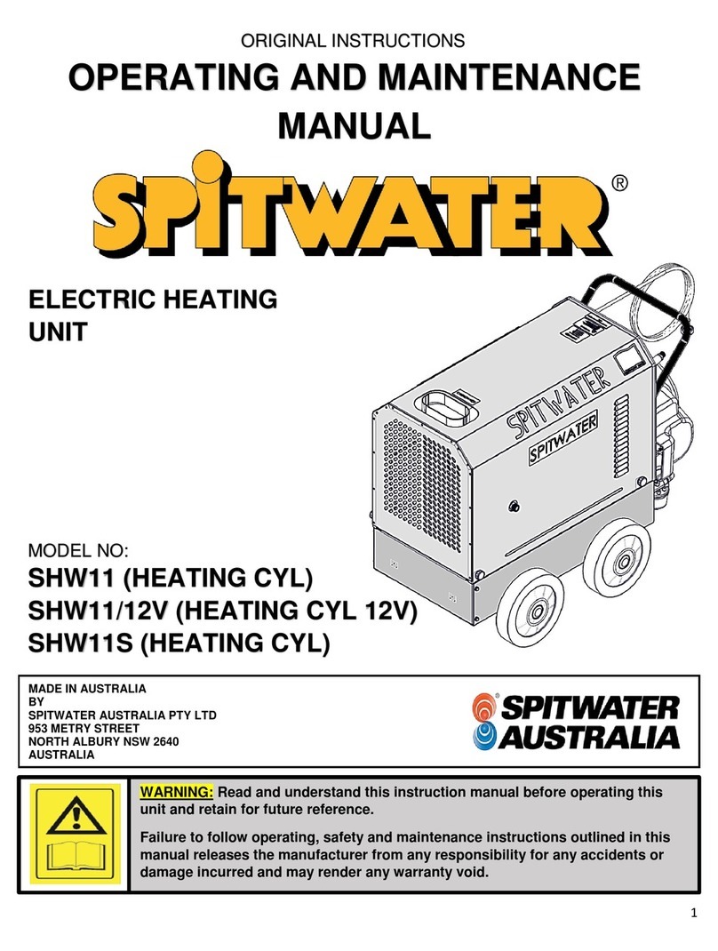
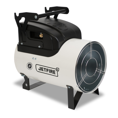
Spitwater JETFIRE DI16 Operating instructions

Spitwater Australia pty Ltd
953 Metry St
North Albury, NSW
Australia
WARNING: Read and understand this instruction manual before operating this unit.
Retain this instruction booklet for future reference.
Failure to follow operating, safety and maintenance instructions outlined in this
manual releases the manufacturer from any responsibility for any accidents or
damages incurred and may render any warranty void
DIESEL / KEROSENE
FIRED HEATER
DI16
ORIGINAL INSTRUCTIONS
OPERATING AND MAINTENANCE
MANUAL
Made in
Korea for:

UNIT
kW
BAR
Kg/H
M3
-
L
V/~/Hz
W
mm
mm
mm
Kg
HEATER
DI16
16.5
8.83
1.37
145
13
230/1/50
70
FUEL SUPPLY
Address
Phone number
550
340
570
13
HEIGHT
WEIGHT (without fuel)
The manufacturer reserves the right to modify designs, features and technical data without notice.
PERFORMANCE
FUEL
FUEL TANK CAPACITY
TECHNICAL DATA
PRODUCT
CONNECTED LOAD
LENGTH
WIDTH
MODEL
HEAT OUTPUT
PUMP PRESSURE
FUEL CONSUMPTION
MINIMUM ROOM VOLUME
Date of purchase
Business name
DIESEL & KEROSENE ONLY
ELECTRICAL
ELECTRICAL SUPPLY
DIMENSION & WEIGHT

The JETFIRE range of portable heaters are designed to give safe, efficient and reliable service
when the correct operating sequence are followed and proper attention is given to cleaning and
and maintenance procedures. This manual is to provide up to date information necessary to the user for
operating, cleaning and servicing the heaters, together with fault-finding techniques and general
specifications, details and diagrams. Please note that the information given herein after may be subject to
revision in compliance with the policy of continual improvements.
The JETFIRE range of heaters should only be used in the manner and purpose for which they were intended
and in accordance with the recommendations and safety precautions detailed in this manual and in
operating instructions and stickers on the unit itself.
All JETFIRE heaters undergo rigorous safety and operational tests before being despatched into the
marketplace however it is still imperative that prior to used, all operators have read and understood all
information and instructions provided and are aware of possible hazards.
The booklet contains important information for the use and safe operation of this heater. Please read and
all warnings before you start using the unit.
Spitwater has an extensive range of spare parts and accessories to suit all your heating needs.
For spare parts and service please contact 1800 SPITWATER
To view our extensive range of industrial heaters visit www.spitwater.com.au
The following symbols are used throughout this instruction booklet in order to mark important paragraphs
or sections that are due particular attention. Their meaning is listed next to them for your attention.
The following symbols are used on the machine in order to warn user of potential injury if not cautious.
Their meaning is listed next to them for your attention.
injury
Electric shock
Disconnect power
before removing
cover
Hot surface
WARNING
WARNING
Do not touch,
will result in
WARNING
INTRODUCTION
GENERAL DESCRIPTION & INTENDED USE
SPARE PARTS AND ACCESSORIES
These are tips
WARNING
result in injury
or death
Failure to follow
instruction could
result in damage
to machine
instruction could
and instructions
to ensure safe
and proper
operation
Failure to follow

WARNING: This heater shall only be used by persons instructed in its use that have been
been expressly authorized to do so. Before using this heater please pay particular attention
to the following safety warnings as failure to do so could result in serious injury.
1 Make sure you have read and understood the whole instruction manual before installing,
operating or carrying out any maintenance on the unit.
2 Warnings and data plates on the machine provide important directions and information
on the safe use of the unit.
3 Besides these operating and safety instructions please make sure that all accident
prevention regulations applicable in the country of use are followed.
4 As well as these operating and safety instructions any standards relating to the
installation and operation of industrial heaters applicable in your country must be
strictly followed.
1 For safe moving of the unit between work areas make sure that the unit has been
switched off and is allowed to cool if necessary.
2 Lift from handle of the machine.
3 For safe transport in and on vehicles make sure the machine is appropriately strapped
in order to avoid it sliding or falling.
1GENERAL
- The heater unit must be positioned on flat stable ground and must be in an upright
position before operating. Do not operate on uneven surface or loose gravel.
- The heater unit must be checked that it is safe and in proper working order before
putting into service and before every use. If the unit is damaged do not use it.
- The heating space must be properly ventilated in compliance with this manual and the
heater unit must be serviced as per maintenance guidelines in this manual to avoid
carbon monoxide build up, which can lead to death.
SAFETY INSTRUCTIONS & PRECAUTIONS
IMPORTANT SAFETY INSTRUCTIONS
AND PRECAUTIONS
GENERAL WARNING
TRANSPORT

2WHILE USING THE HEATER
- Read all instructions before using this heater take care to ensure you fully understand
the instructions concerning electricity and fuel supply.
- Know how to start and stop the unit. Be quite familiar with the controls.
- Allow a minimum room size as listed in the technical specifications.
- Not for domestic use, space heating only.
- Local regulations should be followed as to the installation of industrial heaters.
- Do not operate the heater if it is damaged.
- Never leave the heater unattended whilst running.
- Permanent ventilation to the outside atmosphere must be provided. Allow 96 sq.cm for
every 1000W input divided equally between floor and high levels.
- Do not operate this heater in basements or below ground.
- Do not restrict under any circumstances either the inlet or outlet end of the heater.
- The heater must not be used in close proximity to combustible or flammable materials.
- The heater must operate in a space with clearance of 1m above and behind and 600mm
on the sides. A guard must be placed 900mm away from the heater outlet to prevent the
approach of combustible materials.
- Always use the handle to move the heater after it has been operating as other parts of
the heater may be very hot.
-
Use only clean filtered diesel or kerosene as fuel. Do not refill the fuel tank while the
heater is running or is still hot.
- Follow the maintenance procedures and fault-finding techniques outlined in the manual.
- To prevent injury always disconnect the power plug before disassembling any part of the
heater.
- Do not carry out temporary repairs on worn or damaged electrical cords and plugs.
- Have worn, cut or damaged cords and plugs replaced by an authorised service person or
electrician.
- Do not pull on the electrical cord in order to unplug the unit.
- Do not use this heater in the rain or when it is at risk of being sprayed with water.
3ELECTRICITY SUPPLY
-
The JETFIRE range of heaters is designed to run off 230V Single-Phase 50Hz electrical
supply. The unit should be plugged into a 10A outlet.
- The appliances must be earthed.
- If the Plug needs to be replaced to suit local requirements a qualified electrician should
carry out the replacement taking care to earth the unit and maintain the correct phase
connection as per the wiring diagram.
4FUEL SUPPLY
- Please only use the following fuel types in the heater:
Kerosene with viscosity of 1.3 cSt or Diesel with viscosity of 1.5 cSt.

Temperature Limit Control :
This heater is equipped with a Temperature Limit Control designed to turn off the
heater should the internal temperature rise to an unsafe level. If this device activates
and turns your heater off it may require service.
(Internal Shut-Off Temperature - 212˚F/100˚C ± 10°, Reset Temperature - 176˚F/80˚C ± 10°)
Electrical System Protection :
The heater's electrical system is protected by a fuse mounted to the PCB assembly that
protects the system components from damage. If the heater fails, check the fuse first,
and replace if necessary.
Flame-Out Sensor
The heater uses photocell to see the flame in the combustion chamber. Should the flame
extinguish, the sensor will stop electrical current and the heater will shut off.
Shock(earthquake) automatic shut-off Device
This Heater is equipped with Tip Over switch, In case that earthquake more than 5 magnitude
happens or that heater inclined 5 ~ 10°. Heater will be shut-off by Tip Over switch for safety.
(Refer to Trouble Shooting )
1 Carry out all regular maintenance and inspections as listed in this manual using original
JETFIRE parts where required.
2 Always make sure before carrying out any maintenance that the unit is turned off and
allowed to cool down.
3 Always make sure to disconnect the power plug from the mains outlet before carrying
out any maintenance work on the unit.
4 Never carry out any maintenance work not expressly outlined in this booklet and never
make any technical modifications to this unit.
5
This unit is fitted with safety devices which are set and sealed at the factory. It is very
important these devices receive their routine maintenance to assure your safety as well
as necessary protection of the unit.
6 There are a number of very important components that have been set and sealed at the
factory. Never under any circumstances tamper with, modify or adjust these settings.
7 Make sure this unit is regularly serviced by an authorized JETFIRE agent according to the
servicing requirement outlined in this booklet.
8 Always dispose of unused fuel according to requirements of the local authorities.
SAFETY DEVICES
MAINTENANCE & SERVICING

OPERATING ELEMENTS
Please see operating elements below to help familiarize yourself with the components of this unit.

Figure B
Figure A
Figure G
Figure H

1 Take the heater out of the box and remove the handle from heater. (Figure A)
2 Remove the pre-assembled screws on the shell.
3 Align the holes in the shell with two mounting holes on the handle as shown in Figure B.
4 Secure handle with screws with removed.
Save the shipping carton and packing materials for future storage.
To Start (Normal Operation)
1 Fill the tank with kerosene / diesel until fuel gauge points to "F".
2 Be sure fuel cap is secure.
3 Plug power cord into 230V power outlet. (Figure G)
Turn “Thermostat Control Knob” to desired setting (setting range : 0℃~40℃)
and push operating switch to “ON” position (Figure H), power
indicator lamp and room temp. display will light and heater will start.
NOTE
- The extension cord should be at least six feet long.
- Extension cord wire size requirements are as follows:
6 to 10 feet (1.8 to 3 meters ), use 18 AWG wire.
11 to100 feet (3.4 to 30.4 meters ), use 16 AWG wire.
101 to 200 feet (30.8 to 61 meters), use 14 AWG wire.
To Stop (Normal Operation)
1
Turn the Operating Switch to "OFF" position. Combustion will stop, and the cooling cycle
will begin (Dur. -7 mins). (Room Temp. Display will show "CC" during the cooling cycle)
2
When cooling Cycle is completed (fan stops running), it is safe to unplug the heater.
NOTE
- Unplugging the heater before the Cooling Cycle has ended may cause overheating,
damage to the heater, and could void the warranty.
When the heater is not going to be used for a long period it is to be stored in accordance with the steps shown below.
1 Unscrew Fuel Cap and using an approved kerosene siphon, remove kerosene / diesel.
2 Using a small amount of kerosene, rinse and swirl the kerosene inside of the Fuel Tank.
3 Empty the tank fully.
4 Replace the fuel cap.
5 Repack the unit in original shipping material and store in area free of dust and corrosive vapours.
ASSEMBLY, INSTALLATION AND
OPERATING INSTRUCTIONS
ASSEMBLY
OPERATING INSTRUCTIONS
LONG TERM STORAGE

To maintain this unit in peak working condition during its operating life it is necessary to carry out regular
maintenance operations and replace worn or broken parts immediately upon their failure. We strongly advise
that all maintenance is carried out by an authorized JETFIRE agent using original spare parts.
Failure to follow the maintenance guidelines in this booklet releases the manufacturer from
any responsibility in reference to injuries and damages to both persons and goods.
This also may render any warranty given with the unit void.
General
1 Power cable (Each use)
- Check the power cable / plug for any cuts, abrasions or damage before each use. If damage is
found it must be replaced immediately (Not repaired) by an authorized service
person / electrician.
2 Fuel connections (Each use)
- Check fuel fittings and connections for leaks.
3 Performance (Each use)
- Check machine functionality to ensure it is operating as normal.
- Check the units performance characteristics as specified in technical data.
Should any issue be found contact an authorized JETFIRE agent immediately for repair.
Note
ALWAYS ISOLATE UNIT FROM THE ELECTRICAL SUPPLY BEFORE ATTEMPTING ANY REPAIRS
OR MAINTENANCE.
Replacing Pump Fuel Filter. (Figure K)
1 Unscrew(C.W) Filter bottom from Filter top with adjustable pliers. (Figure J)
2 Remove Filter from Filter top
3 Wash Filter in clean kerosene and Remove Dirt.
4 Put Filter back in Filter Top. and Tighten Filter bottom firmly.
5 Reinstall Back Cover.
Replacing Fuel Filter in Fuel Tank. (Figure J)
1 Pull fuel line off from Fuel Filter neck
2 Carefully Pull fuel filter off from Fuel tank with hand or flat blade screwdriver.
3 Wash Filter with clean Kerosene and replace in tank and attach fuel line to fuel filter neck.
Figure J Figure K
MAINTENANCE INSTRUCTIONS
AND TROUBLESHOOTING
MAINTENANCE INSTRUCTIONS

The table below shows the regular maintenance required for your heater, the maintenance
interval and which maintenance can be done by the owner.
Note - Time interval for checks and replacement listed above are for units subject to normal
operating conditions. Should unit be subject to abnormal conditions (i.e. heavy use or
extreme conditions) times should be reduced accordingly.
- Should unit be subject to very limited use, all checks and if necessary replacements should be
carried out at least once per year.
a short period of time.
(Indicator lamp is flickering and
Dirty Photocell Lens.
Clean Photocell Lens.
Make sure photocell is properly-
room temp.display indicates"E1")
seated in holder.
Replace Electronic Pump.
Check to be sure cooling fan is not-
Cooling Fan is obstructed.
TROUBLESHOOTING
Heater ignites but Control PCB
assembly shuts heater off after
Photocell not properly installed.
Dirty Fuel Filter
Check electrical components see-
FAULT
CAUSE
REMEDY
wiring diagram.
obstructed.
Heater will not ignite but motor
(Indicator lamp is flickering and
room temp.display indicates"E1")
MAINTENANCE SUMMARY
Yearly
Yearly
Yearly
Every 600 Hours
Interval
Every 200 Hrs
Every 200 Hrs
Every 200 Hrs
Maintenance Required
Dirt in Nozzle.
Bad electrical connection between-
Ignitor wire is not Properly attached-
Done By
Owner
Owner
Owner
Service Agent
Service Agent
Service Agent
Service Agent
Wash the pump filter in kerosene or diesel.
Check that all fuel lines are tight and in good condition.
Drain the fuel tank and flush using clean fuel.
Clean the fan blades
Clean or replace the nozzle
Clean photoelectric tube.
Clean and adjust ignition plug gap
runs for a short period of time.
photocell and Control PCB assembly.
Defective Photocell.
Defective Electronic Pump
Clean Fuel Filter.
Clean Nozzle.
Replace Photocell.
Clean & Regap Spark Plug,
Heater ignites but Heater shuts off
Fill tank with kerosene.
Clean Fuel Filter.
Clean Nozzle.
Flush fuel tank with clean kerosene.
Check electrical components-
See wiring diagram.
Attach ignitor wire to spark plug-
to spark plug.
Defective Electronic Pump.
No fuel in tank(completely empty)
Carbon deposits on spark-
Plug and/or improper gap.
Dirty fuel filter.
Dirt in Nozzle.
Water in fuel tank.
Bad electrical connection between-
ignitor and Control PCB assembly.
suddenly.
(Indicator lamp is flickering and
room temp. display indicates"E4")
Shuts up by External Shock or
Check weather conditions. E.g Wind
See Spark Plug.
Replace Electronic Pump.
Defective ignitor
Replace ignitor.

Indicator lamp is flickering and
Check electrical connections See-
room temp. display indicates"E2".
Note - To stop the power lamp from flickering, reset the heater by restarting the unit or by disconnecting
it from the power supply.
- If the fault cannot be identified or corrected using the above list (or remedy suggests contacting
JETFIRE service agent) stop using the machine immediately and contact JETFIRE service
agent to rectify the fault.
Turn operating switch to "OFF" and-
allow to cool(about 10 min.)
Ensure heater cord & extension cord-
are plugged in & check power supply.
Replace PCB board.
4. Check elec. connections See
Wiring Diagram.
Heater does not turn on and
the lamp is not light.
Temperature limit Control device is-
overheated.
No electrical power.
Blown fuse.
Bad electrical connection between-
Temperature limit Control and -
Dirt in Nozzle.
Water in fuel tank.
Flame is unstable and/or
Soot occurs from Hot air outlet.
Clean Nozzle.
Flush fuel tank with clean kerosene.
control PCB.
Fan does not turn when heater
is plugged in and Operating switch
is in the "ON "position.
(Indicator lamp is on)
Turn thermostat control knob to a
Thermostat setting is too low.
higher setting.
Fuel leak at Fuel pipe or Fuel lines.
Tighten Fuel pipe or Replace-
Fuel lines.
Replace Electronic Pump.
Defective Electronic Pump
room temp. display indicates"E3"
Thermistor Failure.
Replace Display PCB in the Back -
Cover See Wiring Diagram
Bad electrical connection between-
Wiring Diagram.
Thermistor and Control PCB.
Thermistor Failure.
Replace Thermistor.
Indicator lamp is flickering and
Table of contents
Other Spitwater Heater manuals
Popular Heater manuals by other brands
Sabiana
Sabiana Atlas Installation and maintenance manual
Generac Power Systems
Generac Power Systems MIH1.2 owner's manual

Adler Europe
Adler Europe AD 7728 user manual
Utilitech
Utilitech CZ464EBKLSCN quick start guide
Myson
Myson 7-4 Installation, operating, maintenance and after sales manual
EQUATION
EQUATION OH-23B instruction manual
Hatco
Hatco GLOMAX GM5AH Series Installation and operating manual
Tylo
Tylo Expression Installation and operating instructions

Zehnder Rittling
Zehnder Rittling Alban Electric ALZER-100-50/F quick start guide

RUSTA
RUSTA 90751064 manual
HeatStar
HeatStar MHU50 Operating instructions and owner's manual
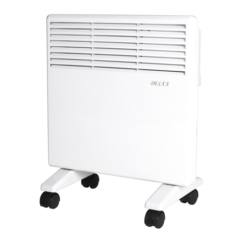
Delfa
Delfa NDK10 instruction manual


