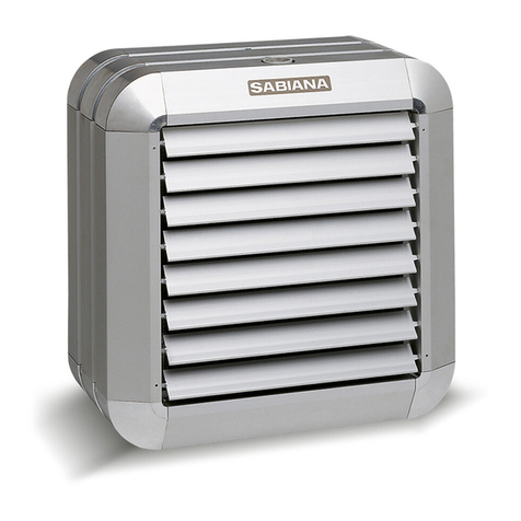
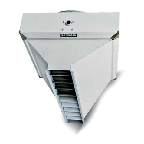
Sabiana Atlas Manual

Via Piave, 53 - 20011 Corbetta (Mi) ITALY
Tel. +39.02.97203.1 ric. autom.
Fax +39.02.9777282 - +39.02.9772820
E-mail: inf[email protected] - Internet: www.sabiana.it
I 05/13
E 05/13
Cod. 4050380
MANUALE DI INSTALLAZIONE
E MANUTENZIONE DEGLI AEROTERMI
INSTALLATION
AND MAINTENANCE MANUAL
FOR UNIT HEATERS
INSTALLATIONS-
UND WARTUNGSMANUAL
FÜR LUFTHEIZER
MANUEL D’INSTALLATION
ET D’ENTRETIEN
DES AEROTHERMES
MANUAL DE INSTALACION
Y MANTENIMIENTO
DE LOS AEROTERMOS
ATLAS
HELIOS

Gli aerotermi Atlas/Helios sono
stati ideati, progettati e costruiti
per riscaldare qualsiasi ambien-
te industriale, commerciale e
sportivo.
L’apparecchio
non può essere impiegato:
• per il trattamento dell’aria
all’aperto
•
per l’installazione in ambien-
ti umidi
• per l’installazione in atmo-
sfere esplosive
• per l’installazione in atmo-
sfere corrosive
Verificare che l’ambiente in cui
è installato l’apparecchio non
contenga sostanze che gene-
rino un processo di corrosio-
ne delle alette in alluminio.
Sono alimentati ad acqua calda
o acqua surriscaldata o vapore
prodotto da generatori (caldaie).
L’apparecchio non è destinato ad
essere usato da persone (bambini
compresi) le cui capacità fisiche,
sensoriali o mentali siano ridotte,
oppure con mancanza di esperien-
za o di conoscenza, a meno che esse
abbiano potuto beneficiare, attraver-
so l’intermediazione di una persona
responsabile della loro sicurezza, di
una sorveglianza o di istruzioni ri-
guardanti l’uso dell’apparecchio.
The unit heaters Atlas and Helios
have been invented, designed
and constructed for the heating
of any industrial, commercial or
sports environment.
The appliance
may not be used:
• for outdoor air treatment
•
for installation in moist rooms
• for installation in explosive
atmospheres
• for installation in corrosive
atmospheres
Make sure that the environment
where the appliance is installed
does not contain substances
that cause the corrosion of the
aluminium fins.
They operate with warm water,
hot water and steam, which is
producted by generators (boilers).
This unit is not intended for use
by persons (including children)
with reduced physical, sensory
or mental capabilities, or lack of
experience and knowledge, unless
they have been given supervision
or instruction concerning use of the
appliance by a person responsible
for their safety.
Die Lufterhitzer Atlas und Helios sind
dazu erdacht, geplant und konstruiert
worden, jedes Ambiente in Industrie,
Handel und Sport mit Wärme zu
versorgen.
Die Geräte darf
nicht eingesetzt werden für:
• die Aufbereitung der Luft
im Freien
• die Installation in feuchten
Räumen
• die Installation in explosiver
Atmosphäre
• die Installation in korrosiver
Atmosphäre
Überprüfen, dass der Raum, in
dem das Gerät installiert wird,
keine Stoffe enthält, die einen
Korrosionsprozess der Aluminium-
rippen bewirken.
Sie werden mit warmen Wasser, heißem
Wasser oder Dampf betrieben, der durch
Generatoren (Heizelemente) erzeugt wird.
Dieses Gerät ist nicht dafür bestimmt,
durch Personen (einschließlich Kinder),
mit eingeschränkten physischen,
sensorischen oder geistigen Fähig-
keiten oder mangels Erfahrung und/
oder mangels Wissen benutzt zu
werden, es sei denn sie werden durch
eine für ihre Sicherheit zuständige
Person beaufsichtigt oder erhielten
von ihr Anweisungen, wie das Gerät
zu benutzen ist.
Les aérothermes Atlas et Helios
ont été conçus projetés et construits
pour chauffer n’importe quel genre de
local, qu’il soit destiné à l’industrie,
au commerce ou au sport.
L’appareil
ne peut pas:
• pour le traitement de l’air
en plein air
• être installé dans des locaux
humides
• être installé dans des
atmosphères explosives
• être installé dans des
atmosphères corrosives
Vérifier que la pièce dans laquelle
l’appareil est installé ne contient
pas de substances pouvant en-
gendrer la corrosion des ailettes
en aluminium.
Ils sont alimentés par de l’eau chaude
ou de l’eau surchauffée ou de la vapeur
produite par des générateurs (chaudières).
L’appareil n’est pas prévu pour
être utilisé par des personnes (y
compris les enfants) dont les
capacités physiques, sensorielles ou
mentales sont réduites, ou dénuées
d’expérience ou de connaissance,
sauf si elles ont pu bénéficier, par
l’intermédiaire d’une personne
responsable de leur sécurité, d’une
surveillance ou d’instructions préalables
concernant l’utilisation de l’appareil.
Los aerotermos Atlas/Helios han
sido diseñados para calefactar
cualquier ambiente de tipo industrial,
comercial y deportivo.
Los aparatos
no se pueden usar para:
• el tratamiento del aire al
aire libre
• su instalación en locales
húmedos
• su instalación en atmósferas
explosivas
• su instalación en atmósferas
corrosivas
Compruebe que la estancia en
la que se está instalado el apa-
rato no contenga sustancias que
generen un proceso de corro-
sión de las aletas de aluminio.
Están alimentados con agua caliente,
agua recalentada o vapor producido
por generadores (calderas).
Este aparato no debe ser utilizado
por personas (incluidos niños) cuyas
capacidades físicas, sensoriales o
mentales estén disminuidas o que
carezcan de experiencia y conoci-
mientos, al no ser que ellas hayan
podido beneficiar, a través de la
intermediación de una persona
responsable de su seguridad, de
una vigilancia o de instrucciones
relativas al uso del aparato.
PRIMA DI INSTALLARE
L’APPARECCHIO
LEGGERE ATTENTAMENTE
QUESTO MANUALE.
BEFORE INSTALLING
THE APPLIANCE PLEASE
STUDY THIS MANUAL
CAREFULLY.
VOR DER INSTALLATION
DIE VORLIEGENDE
ANWEISUNG LESEN.
AVANT L’INSTALLATION
DE L’AEROTHERME LIRE
LA PRESENT NOTICE.
ANTES
DE INSTALAR EL APARATO,
LEER ATENTAMENTE
ESTE MANUAL.
Scopo 2
Prescrizioni di sicurezza 4
Limiti di impiego 5
Trasporto
e identificazione macchina 6
Caratteristiche tecniche 6
Installazione 7
Collegamento idraulico 8
Collegamento a vapore 9
Collegamenti elettrici 9
Pulizia,
manutenzione e ricambi 11
Tabelle tecniche 14
Purpose 2
Security rules 4
Operating limits 5
Transport
and unit identification 6
Technical characteristics 6
Installation 7
Water connection 8
Steam connection 9
Electrical connections 9
Cleaning, maintenance
and spare parts 11
Technical data 14
Verwendungszweck 2
Sicherheitsvorschriften 4
Einsatzgrenzen 5
Transport
und Gerate kennenzeichnung 6
Technische Eigenschaften 6
Installation 7
Wasseranschluss 8
Dampfanschluss 9
Elektrische Verbindungen 9
Wartung, Verwendungszweck
und Ersatzteile 11
Technische Tabellen 14
But 2
Prescriptions de securité 4
Limites d’emploi 5
Transport et identification 6
Caracteristiques techniques 6
Installation 7
Raccordement hydraulique 8
Raccordement à vapeur 9
Connexions electriques 9
Nettoyage, entretien
et pieces de rechange 11
Tabelles techniques 14
Definición 2
Prescripciones de seguridad 4
Límites de uso 5
Transporte y identificación 6
Caracteristicas técnicas 6
Instalación 7
Conexión hidraulica 8
Conexión a vapor 9
Conexiónes eléctricas 9
Limpieza,
mantenimiento y recambios 11
Datos tecnicos 14
2 2A
INDICE
SCOPO
INDICECONTENTS
PURPOSE
INHALT INDICE
BUT
VERWENDUNGSZWECK
DEFINICION

3 3A
I bambini devono essere sorve-
gliati per sincerarsi che non gio-
chino con l’apparecchio.
La batteria degli aerotermi Atlas/
Helios con tubi in acciaio Ø 22 mm
ed alette in alluminio ha, nei con-
fronti delle batterie rame-alluminio
con tubi di piccolo diametro, i se-
guenti vantaggi: il materiale uti-
lizzato per la fabbricazione dei tu-
bi, l’acciaio ed il suo elevato spes-
sore di 1 mm in luogo di 0,3/0,4
mm, forniscono alla batteria una
robustezza e una durata nel tem-
po eccezionali.
Il diametro dei tubi riduce le per-
dite di carico dell’acqua: questo
significa pompe di potenza limi-
tata e una capacità di riscalda-
mento molto rapida.
La batteria utilizza, a parità di resa,
un numero ridotto di tubi: questo
determina una bassa resistenza
al passaggio dell’aria e quindi una
temperatura di uscita dell’aria otti-
male e un lancio molto elevato.
L’ampia spaziatura fra le alette
ed il loro spessore facilitano le
operazioni di pulitura e di manu-
tenzione, indispensabili per con-
servare l’efficienza dell’aerotermo.
La verniciatura speciale assicu-
ra una lunga durata e aumenta
la resa termica.
La batteria è adatta per acqua
calda, acqua surriscaldata o va-
pore, anche ad alta pressione.
L’elettroventilatore è composto
da una ventola con pale in allu-
minio, equilibrata staticamente
e dinamicamente; direttamente
calettata sul motore elettrico
asincrono trifase di tipo chiuso,
isolamento classe B. Supporto a
rete antinfortunistica in robusto
filo d’acciaio, zincocromato; di ti-
po elastico, fissato con interposi-
zione di dispositivi antivibranti.
Gli aerotermi Atlas/Helios sono
stati provati presso l’Istituto di
collaudo Masini.
Children should be supervised
to ensure that they do not play
with the appliance.
With the heat exchanger composed
of steel tubes (diameter 22 mm)
and aluminium fins the unit heaters
Atlas and Helios enjoy the following
advantages in comparison with the
copper-aluminium heat exchanger
mounting small diameter tubes: the
material used for the construction
of the tubes, that is the steel or
copper, has a higher thickness of
1 mm instead of 0,3/0,4 mm and
this gives the heat exchanger an
extraordinary solidity and a long life.
The big tube diameter reduces
the water charge losses and
this means pumps of a reduced
power and a very rapid heating
capacity.
With the same efficiency the heat
exchanger uses a smaller number of
tubes. This causes a low resistance
against the air passage and thus
an ideal discharge temperature of
the air and a very high jet.
The generous distance between the
fins and their thickness facilitate the
cleaning and maintenance operations,
which are indispensable for a long-
term efficiency of the unit heaters.
The special coating assures a
long life and increases the thermic
efficiency.
The heat exchanger can be operated
with warm water, hot water or steam,
also at a high pressure.
The electric ventilator is composed
of a fan with 3 blades (for the
diminuition of the noise level),
sparking free, statically and
dynamically well balanced, which is
directly connected with a hermetically
close, three phase, asynchronous
electric motor, insulation class B.
Finger proof guard made of resistant
steel wire and zinc chromate,
elastical type, fixed with anti-
vibration means.
The unit heaters Atlas and Helios
have been tested at the test
institute Masini, Milan, Italy.
Kinder sollten beaufsichtigt werden,
um sicherzustellen, dass sie nicht
mit dem Gerät spielen
Das Heizelement der Lufterhitzer
Atlas und Helios besteht aus Stahl-
rohren mit 22 mm Durchmesser und
Aluminiumrippen. Im Gegensatz zu
den Kupfer-Aluminium-Heizelementen
mit Rohren kleinen Durchmessers
bieten sich bei diesen Heizelementen
folgende Vorteile: Das für die Rohr-
fertigung verwendete Material, d.h. der
Stahl, und die erhöte Stärke von 1 mm
anstelle von 0,3/0,4 mm verleihen dem
Heizelement eine außergewöhnliche
Robustheit und lange Lebensdauer.
Der große Rohrdurchmesser vermindert
wasserseitige Druckverluste, was gleich-
zeitig Pumpen mit geringer Leistung
und eine sehr schnelle Aufheizfähigkeit
bedeudet. Das Heizelement arbeitet
bei gleicher Leistung mit einer verringerten
Zahl von Rohren.
Daraus ergibt sich ein geringer
Widerstand gegen den Luftdurch-
fluß, was wiederum eine optimale
Austrittstemperatur der Luft und eine
erhöhte Wurfweite zur Folge hat.
Der großzügige Abstand zwischen den
Flügeln und deren Stärke erleichtert die
Reinigungs und Wartungsarbeiten, welche
für die Erhaltung der Funktionsfähigkeit
des Lufterhitzers unabdinglich sind.
Die Speziallackierung gewährleistet
eine lange Lebensdauer und erhöht
die thermische Leistung.
Das Heizelement ist für warmes
Wasser, heißes Wasser und Dampf
(auch bei Hochdruck) geeignet.
Der Elektroventilator besteht aus
einem Ventilator mit Aluminium-
flügeln (zur Verminderung des Schall-
niveaus). Er ist funkenfrei, statisch
und dynamisch ausbalanciert und direkt
mit einem dreiphasigen Asynchron-
motor und Isolationsklasse B gekoppelt.
Ventilatorschutzgitter aus robustem,
zinkverchromtem Stehldraht, elastisch,
durch den Finsatz von Schwingungs-
dämpfern befestigt.
Die Lufterhitzer Atlas und Helios
sind vom Zulassungsinstitut Masini
geprüft.
Il convient de surveiller les enfants
pour s’assurer qu’ils ne jouent pas
avec l’appareil.
La batterie des aérothermes Atlas
et Helios, avec ses tubes en acier
de diamètre 22 mm et ses ailettes en
aluminium, a, par rapport aux bat-
teries cuivre-aluminium et aux tubes
de petit diamètre, les avantages
suivants: le matériel utilisé pour la
fabrication des tubes, l’acier et son
épaisseur élevée d’1 mm au lieu de
0,3/0,4 mm, fournissement batterie
une solidité et une durée exception-
nelle dans le temps.
Le grand diamètre des tubes réduit
les pertes de chargement de l’eau;
ceci signifie que la pompe est
limitée de puissance et que la
capacité de chauffage est très
rapide.
La batterie utilise, pour un même
rendement un nombre réduit de
tubes: ceci détermine une faible
résistance au passage de l’air et
donc une température idéale de
l’air à la sortie avec un flux très fort.
L’ample espacement entre les
ailettes et leur épaisseur facilitent
les opérations de nettoyage et
d’entretien indispensables pour
conserver l’efficacité de l’aérotherme.
La peinture spéciale assure une
longue durée et augmente le
rendement thermique.
La batterie est apte à l’utilisation de
l’eau chaude, de l’eau surchauffée ou
de la vapeur, même à haute pression.
L’électroventilateur est composé d’un
ventilateur hélicoidale à 3 pâles
(pour diminuer le niveau sonore) en
aluminium, antiétincelles, équilibré
statiquement et dynamiquement,
directement accouplé sur le moteur
électrique asynchrone, triphasée, de
type fermé, isolement classe B. Support
moteur type panier en robuste fil d’acier,
zingochromaté, de type élastique, fixé
par interposition de dispositifs anti-
vibrations.
Les aérothermes Atlas et Helios
ont été essayés à l’Institut d’Eassai
Masini.
Los niños han de vigilarse para
asegurarse de que no jueguen con
el aparato.
La bateria de los aerotermos Atlas/
Helios con tubos en acero Ø 22 mm
y aletas en aluminio tiene, en compa-
ración con la baterias cobre-aluminio
con tubos de pequeño diámetro,
las siguientes ventajas: el material
utilizado para la fabricación de los
tubos, acero con un espesor de
1 mm en lugar de 0,3/0,4 mm, da a
la bateria una robustez y una dura-
ción excepcional.
El gran diametro de los tubos reduce
las pérdidas de carga del agua: esto
significa bombas de menor potencia
y una capacidad de calentamiento
más rápida.
La bateria utiliza, a igualdad de
rendimiento, un número menor de
tubos: esto determina una baja
resistancia al paso del aire y por
lo tanto, una temperatura de salida
óptima y un caudal mas elevado.
El ampio espacio entre las aletas y
su espesor facilitan las operaciones
de limpieza y de mantenimiento que
son indispensables para conservar
la eficiencia del aerotermo.
El barnizado especial asegura
una larga duración y aumenta el
rendimiento térmico.
La bateria es idonea para agua
caliente, agua recalentada o vapor,
incluso de alta presión.
El electroventilador está compuesto
por una turbina con álabes en
aluminio antichispa, equilibrada
estáticamente y dinámicamente;
que se acopla perfectamente al
motor eléctrico asincrónico trifásico
de tipo cerrado, aislamiento en clase
B. Soporte en forma de cesta en
robusto hilo de acero, cromado en
cine; de tipo elástico, fiado con inter-
posición de dispositivos antivibrantes.
Los aerotermos Atlas/Helios han sido
sometidos a todo tipo de pruebas en
el Instituto de control Masini.

4 4A
Prima di effettuare qualsiasi in-
tervento assicurarsi che:
1 - l’aerotermo non sia
sotto tensione elettrica;
2 - la valvola di alimentazione
sia chiusa;
3 - attendere il raffreddamento
dello scambiatore.
4 - attendere
l’arresto della ventola.
Assicurarsi
di collegare la messa a terra.
Per sollevare la macchina usare
un mezzo di sollevamento ade-
guato al peso della stessa (vedi
Caratteristiche Tecniche, tabella
pesi). Quando è previsto (gr. 7-10)
usare i golfari.
Sollevarla lentamente, facendo
attenzione che non cada e spo-
stare le cinghie in funzione del
baricentro.
Installare in prossimità dell’ap-
parecchio o degli apparecchi, in
posizione facilmente accessibile,
un interruttore di sicurezza che
tolga corrente alla macchina.
Le ventole possono raggiungere
la velocità di 1.400 g/min. Non
inserire oggetti nell’elettroventi-
latore nè tantomeno le mani.
Non avvicinarsi all’elettroven-
tilatore in moto con indumenti
svolazzanti.
Per installazioni in ambienti dove
l’aerotermo possa essere sog-
getto a urti accidentali, vedi pal-
lonate in locali palestra e/o cam-
po da tennis, è necessario che,
a protezione delle alette direzio-
nali poste sulla bocca di mandata
aria, l’aerotermo sia dotato di un
telaio con rete, che potrà essere
fornito su richiesta.
Before any intervention make
sure that:
1 - the unit is not
under electric tension;
2 - the supply valve is closed;
3 - before any intervention
on the appliance in operation
please wait until the heat
exchanger has cooled down.
4 - wait until the fan
has completly stopped.
Control
that the earthing is all right.
For the transport of the appliance
you have to use suitable lifting
means, which can carry its weight
(see Technical characteristics,
weight table).
Slowly raise the unit and make
sure that it does not fall. Move
the belts in function of the centre
of gravity.
In an easily accesible position
near the appliance or the appliances
has to be mounted a safety switch,
which interrupts the power supply.
The fans can reach a speed of
1.400 RPM. Please don’t introduce
any objects or the hands into the
electric ventilator.
Please don’t approach the electric
ventilator with fluttering clothes.
For installation in environments
where the heater can be subject
to crashes, such as for example
blows with balls in gymnasiums
and/or courts, it is necessary to
fit on the heater a frame with a
safety net, as protection of the air
louvers which are terminal device.
This accessory can be supplied
on request.
Vor jedem Eingriff vergewissern
daß:
1 - der Lufterhitzer nicht
unter Spannung steht;
2 - das Versorgungsventil
geschlossen ist;
3 - wenn das Gerät in Betrieb ist,
muß vor jedem Eingriff
gewartet werden, bis der
Wärmetauscher abgekühlt ist.
4 - bitte wartner
bis Ventilator hält.
Überprüfen, daß die
Erdverbindung hergestellt ist.
Zum Transport des Gerätes ein
seinem Gewicht angemessenes
Hebewerkzeug benützen (siehe
Technische Merkmale, Gewichts-
tabelle).
Das Gerät langsam anheben und
sicherstellen, daß es nicht fällt. Die
Transportgurte in Abhängigkeit vom
Schwerpunkt verschieben.
In der Nähe des Geräts oder der
Geräte ist an einer leicht zugänglichen
Stelle ein Sicherheitsschalter zu
installieren, über den dem Gerät
der Stom entzogen wird.
Die Lüfter können Geschwindigkeiten
von 1.400 UPM erreichen. Führen
Sie keine Fremkörper in den Elektro-
ventilator ein und berühren Sie ihn
nicht mit den Händen.
Dem Ventilator nicht mit flattern- der
Kleidung zu nahe kommen.
Für die Installation in Räume, wo es
die Möglichkeit gibt, daß der Luftheizer
durch zufällige Schläge geschlagen
werden kann (z.B. Schläge mit dem
Ball in Turnhallen und/oedr Tennis-
plätze), ist es nötig, daß einen Rahmen
mit einer Schutznetz auf dem Luft-
ausblas eingebaut wird, als Beschützung
der Luftflügel. Diese Zuberhörteil wird
auf Anfrage geliefert.
Avant d’effectuer n’importe quelle
intervention, s’assurer que:
1 - l’aérotherme ne soit pas
sous tension électrique;
2 - la vanne d’alimentation
soit fermée;
3 - avant chaque intervention,
quand l’appareil était on
fonction, il faut attendre que
l’échangeur soit refroidi.
4 - attendre que le ventilateur
ne tourne pas.
S’assurer
de connecter la masse à terre.
Pour transporter l’appareil utiliser
un moyen de soulèvement en
fonction du poids de celui-ci (voir
Caractéristiques techniques, tableau
poids).
Soulever lentement en faisant
attention que l’appareil ne tombe
pas. Déplacez les courroies en
fonction du barycentre.
Dans une position facilement
accessible près de l’appareil ou
des appareils il faut installer un
interrupteur de securité qui coupe
la tension à l’appareil.
Les hélices peuvent réjoindre des
vitesse de 1.400 TPM. Il ne faut
pas introduire des objets ou le
mains dans l’électroventilateur.
N’approchez pas l’appareil avec
des vêtements flottants.
Pour installations en ambiants oü
l’aérotherme puisse être heurté, par
exémple coups de ballon dans salles
de gymnastique et/ou courts de tennis,
il est necessaire que l’aérotherme
soit doué d’un chassis avec filet,
qui pourra être fourni, sur demande,
pour protéger les ailettes direc-
tionnelles placées sur la bouche
antérieure.
Antes de efectuar cualquier inter-
vención, asegurarse que:
1 - el aerotermo no esté
bajo tensión eléctrica;
2 - la válvula de alimentación
esté cerrada;
3 - esperar el enfriamiento.
4 - esperar que el ventilador
se ferme completamente.
Asegurarse
de conectar la toma de tierra.
Para transportar los aparatos uti-
lizar un medio adecuado al peso
de la misma (ver Características
técnicas, cuadro pesos).
Instalar siempre el aparato con la
red de protección antiaccidente
(opcional), en el caso que exísta
posibilidad de contacto directo con
el ventilador. Correr las correas en
función del centrobárico.
Instalar en una posición facilmente
accessible cerca de aparato o de
los aparatós un interruptor de se-
guridad que apaga el aparato.
Las turbinas pueden alcanzar la
velocidad de 1.400 revoluciones
por minuto. No se pueden introducir
objetos en el electroventilador y
todavia menos las manos.
No aproximar el electroventilador
en movimiento con vestidos flotante.
Para instalaciones en las que el
aerotermo pueda subir accidentales
empujones, por ejemplo choques de
balón en palestras y/o en campos de
tenis, es necesario que el aerotermo
sea dotado de un telar con una red,
puesto sobre la boca de salida de
aire, para la protección de las aletas
de dirección del aire. Este accesorio
puede ser entregado sobre demanda.
PRESCRIZIONI
DI SICUREZZA PRESCRIPTIONS
DE SECURITESECURITY RULES SICHERHEITS-
VORSCHRIFTEN PRESCRIPCIONES
DE SEGURIDAD

5 5A
Non togliere le etichette di sicu-
rezza. In caso di illeggibilità richie-
derne la sostituzione.
Se l’aerotermo deve essere
smontato usare guanti da lavoro.
In caso di sostituzione di compo-
nenti richiedere sempre ricambi
originali.
Solo tecnici (e nessun altro) pre-
cedentemente addestrati, quali-
ficati e autorizzati possono acce-
dere e fare manutenzione alla
macchina.
Non esporre a gas infiammabili.
Proteggere le batterie da peri-
colo di gelo.
Don’t remove the security labels.
If they are unreadable, ask for
their substitution.
For the disassembly of the unit
heater use working gloves.
If pieces have to be substituted,
please always ask for original
spare parts.
Only qualified and authorized,
previously trained technicians
(and no other person) must have
access to the machine and can
perform the maintenance.
Don’t expose to flammable gas!
The battery has to be protected
against frost.
Die Sicherheitsetiketten nicht entfernen.
Wenn sie unleserlich geworden sind,
neue anfordern.
Wenn der Lufterhitzer zerlegt werden
muß, Arbeitshandschuhe benützen.
Wenn Teile ersetz werden müssen,
immer Originalersatzteile verlangen.
Nur geschulte, qualifizierte und
autorisierte Techniker (und kein
anderer) haben Zugang zum Gerät
und können die Wartung vornehmen.
Nicht in Kontakt mit entzündbarem
Gas bringen!
Die Batterie muß vor Frost geschützt
werden.
Ne pas détacher les étiquettes de
sécurité; au cas où elles sont illi-
sibles, en demander la substitution.
Si l’aérotherme doit être démonté,
user des gants de travail.
Dans le cas de sostitution de pieces
toujours demander rechanges
originales.
Seulement techniciens (et personne
d’autre) précédemment formés,
qualifiés et autorisés peuvent
accéder à l’appareil pour effectuer
l’entretien.
N’exposez pas au gaz inflammable.
Protégez la batterie contre le gel.
No quitar las etiquetas de seguri-
dad. En caso de que sean ilegibles,
pedir su substitución.
Si el aerotermo tiene que ser desmon-
tado, utilizar guantes de protección.
En caso de sustitución de piezas,
utilizar siempre recambios originales.
Solamente personal Técnico (exclu-
sivamente) que haya sido instruido,
calificado y autorizado, puede ac-
ceder y efectuar el mantenimiento
de los aparatos.
No exposer a gas inflamable.
Proteger la bateriá contra el frio.
LIMITI DI IMPIEGO LIMITES D’EMPLOI
OPERATING LIMITS
EINSATZGRENZEN LÍMITES DE USO
ACQUA:
Temperatura massima del Fluido
termovettore = max. 170°C
Pressione
di esercizio massima = 16 bar
VAPORE:
Pressione
di esercizio massima = 10 bar
WATER:
Maximum water
temperature = max. 170°C
Maximum
working pressure = 16 bar
STEAM:
Maximum
working pressure = 10 bar
WASSER:
Max. Temperatur
des Kältemediums 170°C
Max.
Betriebsdruck = 16 bar
DAMPF:
Max.
Betriebsdruck = 10 bar
EAU:
Température maximale du fluide
caloporteur = 170°C maxi
Pression
de marche maximale = 16 bar
VAPEUR:
Pression
de marche maximale = 10 bar
AGUA:
Temperatura máxima del fluido
termovector = máx. 170°C
Presión
de ejercicio máxima = 16 bar
VAPOR:
Presión
de ejercicio máxima = 10 bar

L’apparecchio viene trasportato
e consegnato reggiato.
Una volta che l’apparecchio è disim-
ballato controllare che non vi siano
danni e che corrisponda alla fornitura.
In caso di danni o di sigla del-
l’apparecchio non corrispondente
a quanto ordinato, rivolgersi al
proprio rivenditore citando la serie
e il modello.
L’etichetta è posizionata sul retro
dell’apparecchio.
The appliance is transported
packed and duly fixed.
After unpacking please control if
there are no damages and that the
appliance corresponds to your order.
In case of damages or if the article
number of the appliance does not
correspond to your order, please
contact your seller citing the series
and the model numbers.
The label is on the rear side of
the appliance.
Das Gerät wird ordnungsgemäß verpackt
und abgesichert zum Versand gebracht.
Nach dem Auspacken vergewissern
daß das Gerät keine Schäden aufweist
und die Lielerung dem Auftrag entspricht.
Wenn Schäden festgestellt werden
oder de Gerätetyp nicht dem Auftrag
entspricht den Verkäufer unter Angabe
der Serien und Modeilnummer
benachrichtigen.
Die Etikette befindet sich auf der
Rückseite des Geräts.
L’appareil est transporté installé
et soutenu.
Une fois débalté, contrôler qu’il n’y
ait pas de dommages et que l’ap-
pareil corresponde à la fourniture.
En cas de dommages ou d’étiquette
que ne correspond pas à ce qui
a été commandé, s’addresser au
propre revendeur citant la série et
le modéle.
L’étiquette se trouve derrière l’ap-
pareil.
El aparato se transporta y se en-
trega debidamente embalado.
Una vez que el aparato sea desemba-
lado asegurarse de que no haya sufrido
daños y que corresponda al pedido.
En caso de daños o de referencia
de aparato no correspondiente al
pedido, dirigirse al departamento
comercial citando la serie y el mo-
delo.
La etiqueta está posicionada detrás
del aparado.
TRASPORTO E
IDENTIFICAZIONE
MACCHINA TRANSPORT
ET IDENTICATION
TRANSPORT
AND UNIT
IDENTIFICATION
TRANSPORT
UND GERATE
KENNENZEICHNUNG
TRANSPORTE
Y IDENTIFICACION
6 6A
Grandezza
Size
Größe
Taille
Tamaño
1
2
3
4
5
6
7
8
9
10
42
45
46
49
50
52
60
61
62
65
8P
48
51
52
54
56
60
65
67
68
71
6P
56
59
61
64
66
69
-
-
-
-
4P
Livello sonoro a 5 m
Noise level at 5 m
Geräuschpegel 5 m
Niveau sonore à 5 m
Nivel sonoro a 5 m
Motor poles - dB(A)
3,9
4,8
5,7
6,9
9,0
10,5
12,3
16,6
21,8
27,3
3R
2,6
3,2
3,8
4,6
6,0
7,0
8,2
11,1
14,5
18,2
2R
1,3
1,6
1,9
2,3
3,0
3,5
4,3
5,8
7,6
9,6
1R
Contenuto acqua
Water contents
Wasserinhalt
Contenance eau
Contenido agua
l
Peso
Weight
Gewicht
Poids
Peso
Dimensioni
Dimensions
Abmessungen
Dimensions
Dimensiones kgmm
19
22
26
30
33
38
46
55
65
79
22
25
30
34
40
46
55
66
79
95
24
27
33
38
44
51
61
73
88
106
1R 2R 3R
465
465
465
488
488
513
560
575
595
640
C
472
526
580
634
688
742
793
900
1010
1117
A
336
390
444
498
552
606
657
764
874
980
B
375
429
483
537
591
645
696
803
913
1020
D
220
220
220
220
220
220
210
210
210
210
E
130
130
130
130
130
130
140
140
140
140
F
1
1
/
4
”
1
1
/
4
”
1
1
/
4
”
1
1
/
4
”
1
1
/
4
”
1
1
/
4
”
1
1
/
2
”
1
1
/
2
”
1
1
/
2
”
2”
Ø
Grandezza
Size
Größe
Taille
Tamaño
1
2
3
4
5
6
3,9
4,8
5,7
6,9
9,0
10,5
3R
2,6
3,2
3,8
4,6
6,0
7,0
2R
1,3
1,6
1,9
2,3
3,0
3,5
1R
Contenuto acqua
Water contents
Wasserinhalt
Contenance eau
Contenido agua
l
Peso
Weight
Gewicht
Poids
Peso
Dimensioni
Dimensions
Abmessungen
Dimensions
Dimensiones kgmm
19
22
26
30
33
38
22
25
30
34
40
46
24
27
33
38
44
51
1R 2R 3R
477
477
477
500
500
525
C
486
540
594
648
702
756
A
330
384
438
492
546
600
B
406
460
514
568
622
676
D
ATLAS
HELIOS
CARATTERISTICHE
TECNICHE
CARACTERISTIQUES
TECHNIQUES
TECHNICAL
CHARACTERISTICS
TECHNISCHE
EIGENSCHAFTEN CARACTERISTICAS
TECNICAS

I sistemi con cui l’apparecchio
può essere fissato sono:
A - con mensola a parete;
B - con orecchiette
di sospensione a soffitto;
C - con qualsiasi altro mezzo
o materiale ritenuti idonei
dall’installatore.
A - Per fissare
con mensole (optional)
a parete bisogna:
A1 - Stabilire l’altezza
dell’installazione e in base
al tipo di parete predisporre
dei tasselli o altro, atti
a supportare il peso
dell’apparecchio, vedi
Caratteristiche Tecniche.
A2 - Fissare le mensole.
A3 - Sollevare l’apparecchio
con mezzi idonei
e fissarlo alle mensole
(sono consigliate viti M8
e rondelle piane).
The appliance can be fixed
by the following means:
A - with brackets on the wall;
B - with suspension lugs
on the ceiling;
C - by any other means
or material considered
suitable by the installer.
A - The fixing with brackets
(optional) on the wall
is performed as follows:
A1 - Determine
the installation height and
according to the wall type
prepare plugs or other
means, which carry the
weight of the appliance, see
Technical Characteristics.
A2 - Fix the brackets.
A3 - Raise the appliance
with suitable means and
fasten it to the bracket
(We recommend M8
screws with flat washers).
Das Gerät kann mit folgenden
Systemen befestigt werden:
A - mit Konsolen an der Wand;
B - mit Aufhängösen
an der Decke;
C -
mit jedem beliebigen vom
Installateur als geeignet
angesehenen Mittel oder Material.
A - Befestigung
mit Konsolen (Optional)
an der Wand:
A1 -
Die Installationshöhe bestimmen
und in Abhängigkeit von der
Wandbeschaffenheit Dübel oder
andere geeignete Mittel wählen,
welche dem Gewicht des Gerätes
standhalten, s. Technische
Elgenschaften.
A2 - Die Konsolen
an der Wand befestigen.
A3 -
Das Gerät mit geeigneten Mitteln
in die richtige Position heben
und an den Konsolen befestigen
(Es werden M8 Schrauben mit
Flachmutter empfohlen).
Les systèmes avec lesquels
on peut fixer l’appareil sont:
A - avec consoles paroi;
B - avec oreilles
de suspension au plafond;
C -
avec n’importe quel autre moyen
ou matériel retenu approprié
de la part de l’installateur.
A - Pour fixer avec consoles
(optional) à la paroi
il faut:
A1 - Décider la hauteur
de l’installation et selon
le type de paroi utiliser
des chevilles ou autre chose
capable de supporter
le poids de l’appareil (voir
Caractéristiques Techniques).
A2 - Fixer les consoles.
A3 - Soulever
de façon approprié et fixer
l’appareil sur les consoles
(On conseille de vis M8
et rondelles plates).
Los sistemas de fijación
del aparato son los siguientes:
A -
con soportes fijados a la pared;
B - con ganchos de suspensión
fijados al techo;
C - con cualquier otro método
o material que el instalador
considere idoneo.
A - Para fijar con aparatos
(opcional) a la pared,
se necesita:
A1 - Establecer la altura
de la instalación y en base
al tipo de pared, utilizar
clavos de fijación adecuados
al peso del aparato
(ver características técnicas).
A2 - Fijar los soportes.
A3 - Levantar el aparato con un
medio adécuado y fijarlo a
los soportes (se aconsejan
tornillos M8 y arendelas
planas).
A MONTAGGIO
AVVENUTO
CONTROLLARE
CHE L’APPARECCHIO
SIA PERFETTAMENTE
IN BOLLA.
AFTER FIXING THE UNIT
CONTROL THAT
IT IS AT WATER LEVEL
IN ORDER TO AVOID
AIR POCKETS
OR CONDENSATE
STAGNATION.
AUF JEDEN FALL MUSS
SICHERGESTELLT WERDEN.
DASS DIE MONTAGEFLÄCHE
NICHT GENEIGT IST,
UM LUFTSÄCKE ODER
EINEN KONDENSATSTAU
ZU VERMEIDEN.
DANS N’IMPORTE QUEL CAS,
IL FAUT CONTROLER QUE
L’APPAREIL SOIT BIEN
HORIZONTAL (AVEC
UN NIVEAU A BULLE) AFIN
D’EVITER POCHES D’AIR OU
STAGNATION DE RESIDUS
DE CONDENSAT.
UNA VEZ QUE EL MONTAJE
SE HA EFECTUADO,
ASEGURARSE
DE QUE EL APARATO
ESTÉ PERFECTAMENTE
ALINEADO Y NIVELADO.
7 7A
RISPETTARE UN MINIMO
DI DISTANZA (150 mm)
PER L’EVENTUALE
MANUTENZIONE
DI MOTORE E VENTOLA.
PLEASE KEEP A MINIMUN
DISTANCE (150 mm)
FOR THE EVENTUAL
MAINTENANCE
OF MOTOR AND FAN.
EINEN MINDEST-ABSTAND
(150 mm) FÜR DIE
EVENTUELLE WARTUNG
VON MOTOR UND LÜFTER
EINHALTEN.
RESPECTER UN MINIMUM
DE DISTANCE (150 mm)
POUR L’EVENTUEL
ENTRETIEN
DU MOTEUR ET DE L’HELICE.
RESPETAR UNA DISTANCIA
MÍNIMA (150 mm)
PARA EL EVENTUAL
MANTENIMIENTO
DE MOTOR Y TURBINA.
ATTENZIONE!
NON FAR ENTRARE SCORIE
O IMPURITÀ PERCHÈ,
OLTRE A DANNEGGIARE
L’APPARECCHIO STESSO,
POSSONO ESSERE
TRASPORTATE FINO
ALLA CENTRALE TERMICA
E ROVINARE POMPE,
CALDAIE O ALTRO.
ATTENTION!
PLEASE
DON’T INTRODUCE
ANY OBJECTS
INTO THE APPLIANCE,
SINCE THEY CAN
DAMAGE IT AND REACH
THE MAIN BOILER
DESTROYING
PUMPS, BOILERS, ETC.
ACHTUNG!
KEINE FREMDKÖRPER IN DAS
GERÄT GELANGEN LASSEN.
SIE BESCHÄDIGEN SONST
DAS GERÄT UND KÖNNEN
BIS ZUR THERMISCHEN
ZENTRALE VORDRINGEN,
WO SIE PUMPEN,
HEIZEL-EMENTE, ETC.
RUINIEREN.
ATTENTION!
NE PAS INTRODUIRE
DES CORPS ETRANGERS
PARCE QU’ILS PEUVENT
ENDOMMAGER L’APPAREIL
OU ARRIVER JUSQU’A
LA CENTRALE THERMIQUE
ET DETERIORER
LES POMPES,
LES CHAUDIERES, ETC.
ATENCION!
EVITAR LA ENTRADA
DE IMPUREZAS
QUE PUEDAN DAÑAR
EL APARATO
U OTROS ELEMENTOS
DE LA INSTALACIÓN
(BOMBAS CALDERA, ETC.).
INSTALLAZIONE INSTALLATION INSTALLATIONINSTALLATION INSTALACION

8 8A
B - Per fissarlo
con orecchiette
di sospensione a soffitto
(optional) bisogna:
B1 - Decidere la posizione
di installazione.
B2 - Procurarsi funi metalliche,
catenelle, tiranti, sbarre
o altro adatti a sostenere
l’apparecchio in 4 punti
ed a fissarlo al soffitto
in maniera stabile.
B3 - Fissare le quattro
orecchiette di sospensione
all’apparecchio con 4
viti M8 e rondelle piane.
Serrare bene.
B4 - Con mezzi idonei,
sollevare l’apparecchio e
fissarlo alle sospensioni.
B - The fixing
with suspension lugs
on the ceiling
is performed as follows:
B1 - Determine
the installation position.
B2 - Prepare wire ropes,
pull chains, bars
or similar tools to fix
the appliance on 4 points
on the ceiling
in a stable way.
B3 -
Fix the four suspension lugs
(optional) to the appliance
by means of 4 M8 screws
with flat washers.
TighTen very well.
B4 - Raise the appliance with
suitable means and fasten it
very well to the suspensions.
B - Befestigung
mit Aufhängösen
an der Decke:
B1 - Die Installationsposition
bestimmen.
B2 - Stahlseite, Zugketten,
Schienen o.ä. besorgen,
die das Gerät bei der stabilen
Befestigung an 4 Punkten
der Decke in Position halten.
B3 - Die vier Aufhängösen
(Optional) durch 4
M8-Schrauben mit Flach-
mutter am Gerät befestigen.
Schrauben feST anziehen.
B4 - Das Gerät mit geeigneten
Mitteln anheben und gut an
der Aufhängung befestigen.
B - Pour le fixer
avec des oreilles
de suspension
au plafond il faut:
B1 - Décider la position
de l’installation.
B2 - Se procurer des cordes
métalliques, petites chaînes
verboquet, barres ou autre
chose capable de soutenir
sur 4 points et le fixer
au plafond de façon stable.
B3 - Fixer les 4 oreilles
de suspension (optional)
à l’appareil avec 4 vis M8
et rondelles plates.
bien Serrer.
B4 -
Soulever l’appareil de façon
appropriée et le fixer
très bien aus suspensions.
B - Para fijarlo
a los anillos de suspensión
al techo (opcional),
se necesita:
B1 - Decidir el lugar
de la instalación.
B2 - Utilizar cable metálico,
cadenas, tirantes, barras
o cualquier otro sistema
de anclaje del aparato
en 4 puntos y fijarlo al techo
de manera estable.
B3 -
Fijar las 4 placas de suspen-
sión al aparato con 4 tornillos
M8 y arandelas planas.
apreTar y ajuSTar
correcTamenTe.
B4 - Levantar el aparato
de manera adecuada
y fijarlo a las suspensiones.
PRESSIONE MAX.
DI ESERCIZIO: 16 BAR. MAXIMUM OPERATION
PRESSURE: 16 BAR. MAXIMALER
BETRIEBSDRUCK: 16 BAR.
PRESSION MAXIMUM
PENDANT LE
FONCTIONNEMENT: 16 BAR.
PRESIÓN MÁXIMA
DE EJERCICIO: 16 BAR.
RICORDARSI, IN CASO
DI FUNZIONAMENTO CON
ACQUA SURRISCALDATA,
CHE È OBBLIGATORIO
MONTARE LE FLANGE
(CON GUARNIZIONI NON
IN GOMMA) AL POSTO
DEL GIUNTO.
PLEASE REMEMBER
THAT IN CASE OF
HOT WATER OPERATION
AT THE POINT
OF THE JOINT HAVE TO BE
MOUNTED FLANGES
WITH SEALS OF ANOTHER
MATERIAL THAN RUBBER.
BEIM BETRIEB
MIT HEISSEM WASSER
MUSS FÜR DIE
DICHTUNGEN AN DEN
ANSCHLUSSFLANSCHEN
UNBEDINGT EIN ANDERES
MATERIAL ALS GUMMI
VERWENDET WERDEN.
SE RAPPELER EN CAS
DE FONCTIONNEMENT
AVEC L’EAU SURCHAUFFE
QU’IL EST OBLIGATOIRE
DE MONTER LES BRIDES
AVEC DES GARNITURES
PAS EN CAOUTCHOUC,
A LA PLACE DU JOINT.
EN CASO
DE FUNCIONAMIENTO
CON AGUA RECALENTADA,
ES OBLIGATORIO
UTILIZAR BRIDAS
(CON JUNTAS RESISTENTES
A ALTAS TEMPERATURAS)
EN LUGAR DE RACORD.
COLLEGAMENTO
IDRAULICO RACCORDEMENT
HYDRAULIQUE
WATER
CONNECTION WASSER-
ANSCHLUSS CONEXION
IDRAULICA
Schema di alimentazione
con acqua calda o surriscaldata.
IN = MANDATA
OUT = RITORNO
A = INSTALLAZIONE
A SOFFITTO
B = INSTALLAZIONE
A PARETE
Per evitare perdite utilizzare
canapa e pasta verde per colle-
gare tanto in entrata quanto in
uscita l’apparecchio, con un giun-
to a 3 pezzi e valvola a sfera.
Diagram for the warm water
and hot water supply.
IN = FLOW
OUT = RETURN
A = CEILING
INSTALLATION
B = WALL
INSTALLATION
Connect the appliance
at the inlet and at the outlet
with a three-part joint and
a ball valve; seal with hemp
and green paste.
Schema für den Einlauf von
warmen oder heißem Wasser.
IN = VORLAUF
OUT = RÜCKLAUF
A = DECKEN-
INSTALLATION
B = WAND-
INSTALLATION
Das Gerät am Ein- und Austritt
mittels Hanf und Dichtpaste
mit einem 3-teiligen Zwischenstück
und einem Kugelventil verbinden.
Schéma d’alimentation
avec eau chaude surchauffée.
IN = ENTREE
OUT = RETOUR
A = INSTALLATION
AU PLAFOND
B = INSTALLATION
A PAROI
Raccorder l’appareil
soit en entrée qu’en sortie
avec un joint à 3 pièces
et soupape à bille avec chanvre
et pâle de garniture.
Esquema de alimentación
con agua caliente o recalentada.
IN = IDA
OUT = RETORNO
A = INSTALACION
AL TECHO
B = INSTALACION
A LA PARED
Para évitar fugas, utilizar juntas de
estanquecidad adecuadas (teflón,
cáñamo o similar). Tanto en impulsión
como en retorno, conectar mediante
racord universal y válvula esférica.

9 9A
Prima di effettuare i collegamenti
ai motori assicurarsi che non ci
sia tensione.
Installare in prossimità dell’ap-
parecchio o degli apparecchi, in
posizione facilmente accessibile,
un interruttore di sicurezza che
tolga corrente alla macchina.
Before the connection of the
motors make sure that the main
switch is in the “OFF” position.
In an easily accesible position near
the appliance or the appliances
has to be mounted a safety switch,
which interrupts the power supply.
Bevor die Motoren angeschlossen
werden, muß überprüft werden, daß
der Hauptschalter sich in OFF-Position
(auf 0) befindet.
In der Nähe des Geräts oder der
Geräte ist an einer leicht zugänglichen
Stelle ein Sicherheitsschalter zu
installieren, über den dem Gerät der
Stom entzogen wird.
Avant d’effectuer les connexions aux
moteurs s’assurer que l’interrupteur
soit sur 0 = OFF.
Dans une position facilement ac-
cessible près de l’appareil ou des
appareils il faut installer un inter-
rupteur de securité qui coupe la
tension à l’appareil.
Antes de efectuar la conexión de
los motores, asegurarse que el in-
terruptor se encuentre en la posi-
ción “OFF”.
Instalar en una posición facilmente
accessible cerca de aparato o de
los aparatós un interruptor de segu-
ridad que apaga el aparato.
ATTENZIONE!
METTERE
UNO SFIATO D’ARIA
NEL CASO CHE L’ANELLO
DI DISTRIBUZIONE
DELL’ACQUA
O DEL FLUIDO SIA IN
UNA POSIZIONE INFERIORE
RISPETTO A QUELLA
DELL’APPARECCHIO.
ATTENTION!
MOUNT
AN AIR BREATHER, IF
THE DISTRIBUTION RING
OF THE WATER
OR THE FLUID
IS IN A LOWER POSITION
THAN THE APPLIANCE.
ACHTUNG!
EIN ENTLÜFTUNGSROHR
ANBRINGEN, WENN
DER VERTEILERRING
DES WASSERS
ODER DER FLÜSSIGKEIT
SICH UNTERHALB
DES GERÄTES BEFINDET.
ATTENTION!
METTRE
UN EVENT D’AIR
AU CAS OU L’ANNEAU
DE DISTRIBUTION DE L’EAU
OU DU FLUIDE SOIT
INFERIEUR A LA POSITION
DE L’APPAREIL.
ATTENCION!
PONER
UN PURGADOR DE AIRE
EN CASO DE QUE
EL ANILLO DE DISTRIBUCIÓN
DEL AGUA O DEL FLUIDO
ESTÉ EN UN NIVEL INFERIOR
RESPECTO AL APARATO.
PRESSIONE MAX.:
10 BAR. MAXIMUM PRESSURE:
10 BAR. MAXIMALER
BETRIEBSDRUCK: 10 BAR. PRESSION MAXIMUM:
10 BAR. PRESIÓN MÁXIMA:
10 BAR.
Il collegamento a vapore
va eseguito
secondo questo schema:
IN = MANDATA
OUT = RITORNO
A = INSTALLAZIONE
A SOFFITTO
B = INSTALLAZIONE
A PARETE
1 - VALVOLA A SFERA
2 - FLANGIA
3 - FILTRO
4 - SCARICATORE
DI CONDENSA
The steam connection
is performed according to
the present diagram:
IN = FLOW
OUT = RETURN
A = CEILING
INSTALLATION
B = WALL
INSTALLATION
1 - BALL VALVE
2 - FLANGE
3 - FILTER
4 - CONDENSATE
DISCHARGER
Der Dampfanschluß wird
gemäß folgenden Schema
hergestellt:
IN = VORLAUF
OUT = RÜCKLAUF
A = DECKEN-
INSTALLATION
B = WAND-
INSTALLATION
1 - KUGELVENTIL
2 - FLANSCH
3 - FILTER
4 - KONDENS-
WASSERABLASS
Le raccordement à vapeur
doit être exécuté
selon le schéma suivant:
IN = ENTREE
OUT = RETOUR
A = INSTALLATION
AU PLAFOND
B = INSTALLATION
A PAROI
1 - SOUPAPE A BILLE
2 - BRIDE
3 - FILTRE
4 - DECHARGEUR
DE CONDENSAT
En enlace a vapor
se efectua
según el siguiente esquema:
IN = IDA
OUT = RETORNO
A = INSTALACION
AL TECHO
B = INSTALACION
A LA PARED
1 - VALVULA ESFERICA
2 - BRIDA
3 - FILTRO
4 - DESCARGADOR
DE CONDENSADOS
COLLEGAMENTI
ELETTRICI CONNEXIONS
ELECTRIQUES
ELECTRICAL
CONNECTIONS ELEKTRISCHE
VERBINDUNGEN CONEXIONES
ELECTRICAS
COLLEGAMENTO
A VAPORE E
FLANGE SALDATE
RACCORDEMENT
A VAPEUR ET
BRIDES SOUDEES
STEAM
CONNECTION AND
WELDED FLANGES
DAMPFANSCHLUSS
MIT GESCHWEISSTEN
FLANSCHEN
ENLACE A VAPEUR
Y BRIDAS

10 10A
Togliere il coperchietto della mor-
settiera del motore e procedere
al collegamento elettrico, che può
essere di tipo:
– Motore
ad una sola velocità
trifase 230/400V
– Motore a scorrimento
con protezione termica
(klixon), 400V,
4 o 6 poli trifase
Le pagine 14 e 15 mostrano i vari
schemi di collegamento.
Controllare la messa a terra.
Una volta effettuato il collega-
mento elettrico, provare il senso
di rotazione della ventola.
Nel fare ciò, verificare che l’aria
esca dalla parte opposta del mo-
tore.
Nel caso di rotazione scorretta,
togliere tensione ed invertire una
fase sulla morsettiera.
Quindi chiudere il coperchio del-
la morsettiera del motore e strin-
gere il passacavo.
Remove the cover from the terminal
board of the motor and perform
the electrical connection, which
can be:
– Motor
with one speed,
three-phase 230/400V
– Sliding motor with
thermal protection (klixon),
4 or 6 poles, three-phase
400V, single tension
On pages 14 and 15 the various
connection diagrams are shown.
Control the earthing.
After having performed the electrical
connection separately control the
rotation sense of the motors and
make sure that the air gets out at
the side opposed to the motor.
When controlling the rotation
sense of the motor keep away
from the rotating fan.
Than close the cover of the terminal
board of the motor and tighten the
cable guidance.
Den Deckel vom Klemmenbrett
des Motors entfernen und die
elektrische Verbindung herstellen,
welche folgender Art sein kann:
– Dreiphasiger Motor
mit einer Geschwindigkeit,
230/400V
– Dreiphasiger Gleitmotor
mit Thermoschutz (Klixon),
400V, 4 oder 6 Pole
Auf den Seiten 14 und 15 sind die
verschiedenen Schaltschemen
dargestellt.
Die Erdung überprüfen.
Nach Herstellung der elektrischen
Verbindungen ist auf jeden Fall
die Drehrichtung der Motoren zu
überprüfen, um sicherzugehen
daß die Luft an der dem Motor
entgegengesetzten Seite austritt.
Dann den Deckel des Motor-
Klemmenbrettes schließen und die
Kabelführung gut befestigen.
Bei falscher Drehrichtung den Haupt-
schalter auf OFF (AUS) stellen und
auf dem Klemmenbrett eine Phase
umkehren.
Retirer le couvercle de la boîte à
bornes du moteur. Effectuer la
connexion électrique qui peut être
du type:
– Moteur
à une seule vitesse,
triphasé, 230/400V
– Moteur à glissement avec
protection thermique (Klixon),
4 ou 6 pôles, triphasé,
400V, monotension
Les pages 14 et 15 montrent les
différents schhémas de connexion.
Contrôler la prise de terre.
Quand la connexion électrique est
effectuée, contrôler individuellement
le sens de rotation des moteurs en
vérifiant que l’air sorte de la partie
opposée au moteur.
En cas où la position est incorrecte,
mettre l’interrupteur général sur
OFF et inverser una phase de la
boîte à bornes.
Donc fermer le couvercle de la
boîte à bornes du moteur et serrer
le chaumard.
Quitar la tapa del motor donde se
encuentran todos los cables y pro-
ceder a la conexión eléctrica que
puede ser de los siguientes tipos:
– Motor
con una sola velocidad
trifásico 230/400V
– Motor deslizante con
protección térmica (Klixon),
4 ó 6 polos, trifásico 400V,
monotensión
Las páginas 14 y 15 ilustran los dife-
rentes esquemas para la conexión.
Conectar la toma de tierra.
Una vez efectuada la conexión
eléctrica, comprobar el sentido de
giro de la turbina. Mientras se hace
esto, verificar que el aire sea im-
pulsado hacia la parte opuesta del
motor.
En el caso de que el sentido de
giro no sea correcto, desconectar
la tensión e invertir una fase en la
caja de conexiones del motor.
Cerrar la caja de conexión y ajustar
bien bloqueando el cable.
CHI HA ESEGUITO
LA MESSA IN OPERA
DELL’AEROTERMO
DEVE ORIENTARE
LE ALETTE DEFLETTRICI
NEL SENSO VOLUTO
DI DIREZIONE DELL’ARIA.
THE PERSON
WHO PREPARES
THE UNIT HEATER
FOR OPERATION
HAS TO ORIENTATE
THE DEFLECTOR FINS
IN THE SENSE
OF THE AIR DIRECTION.
DAS FÜR DIE INBETRIEB-
NAHME DES LUFTERHITZERS
VERANTWORTLICHE
PERSONAL MUSS
DIE DEFLEKTOR-FLÜGEL
IN DER VOM LUFTSTROM
VORGEGEBENEN RICHTUNG
AUSRICHTEN.
LA PERSONNE
QUI A EFFECTUE
LA MISE EN FONCTION
DE L’AEROTHERME
DOIT ORIENTER
LES AILETTES DANS
LE SENS OU L’ON VEUT
QUE L’AIR SOIT DIRIGE.
AL EFECTUAR
LA PUESTA EN MARCHA
DEL AEROTERMO
ORIENTAR
LOS DEFLECTORES
EN EL SENTIDO DESEADO
DE DIRECCION DEL AIRE.

11 11A
PRIMA
DI QUALSIASI PULIZIA
E MANUTENZIONE
ISOLARE L’APPARECCHIO
DALLA FONTE DI ENERGIA.
BEFORE ANY CLEANING
OR MAINTENANCE
DETACH THE APPLIANCE
FROM
THE POWER SOURCE.
VOR DER REINIGUNG
ODER DER WARTUNG
MUSS DAS GERÄT IMMER
VON DER STROMDUELLE
ISOLIERT WERDEN.
AVANT DE FAIRE N’IMPORTE
QUEL NETTOYAGE
OU ENTRETIEN
ISOLER L’APPAREIL
DE LA SOURCE D’ENERGIE.
ANTES DE EFFECTUAR
CUALQUIER OPERACIÓN
DE LIMPIEZA
Y MANTENIMIENTO,
EL APARATO TIENE
QUE SER DESCONECTADO
DE LA FUENTE DE ENERGIA.
Solo personale addetto alla ma-
nutenzione e precedentemente
addestrato, può intervenire sulle
apparecchiature.
MOTORE: gli aerotermi monta-
no dei motori di tipo chiuso, con
cuscinetti autolubrificanti e non
richiedono alcun intervento di
manutenzione.
BATTERIA: le batterie di scam-
bio termico debbono essere man-
tenute in perfetto stato per garan-
tire le caratteristiche tecniche di
progetto. Controllare ogni tre mesi
che il pacco alettato non presenti
ostruzioni al passaggio dell’aria.
Se necessario pulire utilizzando
un getto di aria, acqua o di va-
pore a bassa pressione, avendo
cura di proteggere il motore elet-
trico, per evitare danneggiamenti.
ELETTROVENTILATORE: nel
caso vengano avvertiti rumori o
vibrazioni del ventilatore, verifi-
care il serraggio dei bulloni di fis-
saggio del motore, del supporto
e della ventola. Nel caso di sosti-
tuzione del motore, ricordarsi di
controllare il senso di rotazione,
vedi capitolo Collegamenti Elet-
trici.
RICAMBI: per ordinazione delle
parti di ricambio citare sempre
il modello dell’apparecchio e la
descrizione del componente.
Only previously trained maintenance
personnel is authorized to work on
the appliances.
MOTOR: the unit heaters mount
closed motors with self-lubricating
bearings and are maintenance
free.
HEAT EXCHANGER: the heat
exchanger batteries have to be
kept in a perfect condition to
guarantee the projected technical
characteristics. Please control
every three months that the fin
package does not present any
obstructions at the air passage;
if necessary clean with a low-
pressure jet of air, water or steam
and take care to protect the electrical
motor in order to avoid damages.
ELECTRICAL VENTILATOR: if
you note noise or vibrations caused
by the fan, check it the fixing bolts
of the motor, the support and
the fan are well fastened. If the
electric motor is substituted, don’t
forget to control the rotation sense,
see section “Electrical Connections”.
SPARE PARTS: in the spare part
orders please always indicate
the model of the appliance and
the description of the component.
Nur qualifiziertes und geschultes
Personal darf die Geräte wartung
und Reparaturen vornehmen.
MOTOR: in die Lufterhitzer sind
Motoren in geschlossener Aus-
führung mit auf Lebensdauer
geschmierten Lagern montiert.
Motor und Lager sind wartungsfrei.
HEIZELEMENT: die Wärmetauscher
müssen perfekt gewartet werden,
um die vorgesehenen technischen
Leistungen zu erfüllen. Alle drei
Monate ist zu überprüfen, ob das
Lamellenpaket im Luftdurchlaßbereich
keine Verstopfungen aufweist. Wenn
notwendig, ist es bei Niederdruck mit
einem Luft-, Wasser- oder Dampfstrahl
zu reinigen, wobei der Elektromotor
gegen Beschädigungen geschützt
werden muß.
ELEKTROVENTILATOR: wenn
Motorgeräusche oder Vibrationen
registriert werden, müssen die
Befestigungschrauben von Motor,
Gehäuse und Lüfter kontrolliert
und eventuell festgezogen werden.
Falls der Elektromotor ausgetauscht
werden muß, immer die Drehrichtung
kontrollieren (siehe Kapitel “Elektrische
Verbindungen”).
ERSATZTEILE: bei Ersatzteil-
bestellungen sind immer das jeweilige
Gerätemodell und die Teibezeichnung
anzugeben.
Seulement un personnel formé
pour l’entretien et précédemment
préparé peut intervenir sur les
appareils.
MOTEUR: les aérothermes montent
des moteurs de type fermé avec
roulements autolubrifiants qui ne
demandent aucun entretien.
BATTERIE: les batteries d’échange
thermique doivent être maintenues
en parfait état pour garantir les
caractéristiques techniques du
projet. Contrôler tous les trois mois
que le paquet aileté ne présente
pas d’obstructions au passage de
l’air; si nécessaire nettoyer utilisant
un jet d’air, eau ou de vapeur a
basse pression en ayant soin de
protéger le moteur électrique pour
éviter des dommages.
ELECTROVENTILATEUR: pour
les cas où il y ait des bruits ou
des vibrations qui proviennent du
ventilateur, vérifier le serrage des
boulons de fixage du moteur, du
support et de l’hélice. Dans le cas
de substitution du moteur électrique
se rappeler de contrôler le sens de
rotation, voir paragraphe “connexions
électriques”.
PIECES DE RECHANGE: pour
commander des piéces de rechanges
il faut toujours citer le modéle de
l’appareil et le nom du composant.
Sobre los aparatos puede intervenir
solo y exclusivamente el personal
autorizado del mantenimiento.
MOTOR: los aerotermos van equi-
pados con motores de tipo cerrado
con cojinetes autolubrificados y
no necesitan ningún tipo de inter-
vención o de mantenimiento.
BATERIA: las baterias de inter-
cambio térmico tienen que man-
tenerse en perfecto estado para
garantizar las condiciones térmica
de proyecto. Controlar cada tres
meses que el bloque con las aletas
no obstruya el paso del aire. Si es
necesario, limpiar utilizando aire
comprimido, un chorro de agua o
de vapor a baja presion, protegiendo
el motor eléctrico para evitar posi-
bles daños.
ELECTROVENTILADOR: en caso
de ruidos o vibraciones del venti-
lador, verificar que las fijaciones del
motor, del soporte y de la turbina
estén bien apretadas. En caso de
sustitución del motor, verificar el
sentido de giro (ver el capítulo de
conexiones eléctricas).
RECAMBIOS: para los pedidos
de las piezas de recambio, citar
siempre el modelo del aparato y
la descripción del componente.
PULIZIA,
MANUTENZIONE
E RICAMBI
NETTOYAGE,
ENTRETIEN ET
PIECES DE RECHANGE
CLEANING,
MAINTENANCE
AND SPARE PARTS
WARTUNG,
VERWENDUNGSZWECK
UND ERSATZTEILE
LIMPIEZA,
MANTENIMIENTO
Y RECAMBIOS

Poli
/
Poles
/
Polig
/
P
ôles
/
Polos
6
Poli
Poles
Pôles
Polig
Polos
8
Poli
Poles
Pôles
Polig
Polos
6
Poli
Poles
Pôles
Polig
Polos
8
Poli
Poles
Pôles
Polig
Polos
6
Poli
Poles
Pôles
Polig
Polos
8
Poli
Poles
Pôles
Polig
Polos
6
Poli
Poles
Pôles
Polig
Polos
8
Poli
Poles
Pôles
Polig
Polos
4
Poli
Poles
Pôles
Polig
Polos
6
Poli
Poles
Pôles
Polig
Polos
4
Poli
Poles
Pôles
Polig
Polos
6
Poli
Poles
Pôles
Polig
Polos
4
Poli
Poles
Pôles
Polig
Polos
6
Poli
Poles
Pôles
Polig
Polos
4
Poli
Poles
Pôles
Polig
Polos
6
Poli
Poles
Pôles
Polig
Polos
6
Poli
Poles
Pôles
Polig
Polos
8
Poli
Poles
Pôles
Polig
Polos
4
Poli
Poles
Pôles
Polig
Polos
6
Poli
Poles
Pôles
Polig
Polos
6
5
4
3
2
1
7
8
9
10
AltezzA
HeigHt
H
öHe
HAuteur
AlturA
m
AltezzA
HeigHt
H
öHe
HAuteur
AlturA
max. m
lAncio
tHrow
wurfweite
Portée
AlcAnce
m
AreA
cover
fläcHe
surfAce
AreA
m2
Zona d'influenza per installazione a:
Mounting heights:
Wirkungsbereich bei Installation an der:
Zone d’influence pour installation:
Zona influencia instalación en:
Parete
Horizontal discharge
Wand
Parois
Pared
Soffitto
Vertical discharge
Decke
Plafond
Techo
m3/h W °CdB(A)
PortAtA AriA
Air flow
luftdurcHsAtz
débit d’Air
cAudAl Aire
emissioni
termicHe
tHermAl
emission
w
ärme-
leistung
PuissAnce
tHermique
emision
termicA
temPerAturA
uscitA AriA
Air leAving
temPerAture
Austritts-
temPerAtur
temPérAture
sortie Air
temPerAturA
sAlidA Aire
livello sonoro
A 5
m
noise level
At 5
m
scHAllPegel
in 5
m
AbstAnd
niveAu sonore
à 5
m
nivel sónoro
A 5
m
grAndezzA
/
size
/
grö
ß
e
tAille
/
tAmAño
velocità
(giri/minuto)
sPeed
(r.p.m.)
dreHzAHl
(U/min)
vitesse
(tr/min)
velocidAd
(rev./min.)
modello
model
modell
modèle
modelo
2,5÷3,5
2,5÷3
8
5,5
4
3
50
36
3÷4
2,5÷3,5
11
7,5
4,5
3,5
60
45
3÷4
2,5÷3,5
14
10
5
4
70
50
3,5÷4,5
3÷4
16
12
5,5
4,5
80
60
4÷5
3,5÷4,5
20
15
6
5
100
75
4÷5,5
4÷5
25
18
7
6
130
110
4÷5
3,5÷4
24
18
7
6
120
100
4÷5,5
3,5÷4,5
26
20
9
7
160
130
4÷6
3,5÷5
28
21
11
8
200
150
4÷6
4÷5
30
22
12
9
220
160
4
6
4
6
4
6
4
6
4
6
4
6
6
8
6
8
6
8
6
8
46A11
46A12
46A13
46A21
46A22
46A23
46A31
46A32
46A33
46A41
46A42
46A43
46A51
46A52
46A53
46A61
46A62
46A63
46H11
46H12
46H13
46H21
46H22
46H23
46H31
46H32
46H33
46H41
46H42
46H43
46H51
46H52
46H53
46H61
46H62
46H63
65
65
65
67
67
67
68
68
68
71
71
71
–
44200
53500
–
62900
72700
–
81400
98800
–
97800
118600
–
41
48
–
42
48
–
41
48
–
42
47
68A71
68A72
68A73
68A81
68A82
68A83
68A91
68A92
68A93
68A101
68A102
68A103
–
–
–
–
–
–
–
–
–
–
–
–
60
60
60
61
61
61
62
62
62
65
65
65
–
37100
43800
–
52200
59700
–
67600
81100
–
79200
97300
–
44
52
–
45
52
–
44
52
–
44
52
1350
1350
1350
1350
1350
1350
1000
1000
1000
1000
1000
1000
900
900
900
900
700
700
700
700
Atlas Helios
5800
5400
5200
8500
7600
7000
10600
10000
9500
12500
11900
11400
56
56
56
59
59
59
61
61
61
64
64
64
66
66
66
69
69
69
–
11170
12940
–
15600
17700
–
23850
27700
–
30840
35260
–
40600
46310
–
51780
59380
–
38
44
–
38
42
–
38
43
–
40
45
–
39
43
–
38
43
48
48
48
51
51
51
52
52
52
54
54
54
56
56
56
60
60
60
–
8500
9790
–
11880
13390
–
17940
20710
–
23290
26630
–
30910
35250
–
40390
46430
–
41
48
–
41
46
–
42
47
–
42
48
–
43
48
–
43
48
1490
1400
1330
2315
2100
2010
3400
2960
2750
4230
3525
3120
5600
5280
4550
6920
6450
5570
1055
1010
960
1640
1440
1380
2215
1995
1850
2845
2350
2080
3630
3470
2990
4700
4225
3720
4400
4100
3800
6000
5500
5000
8000
7500
7000
9500
8800
8450 1,15
50
1,10
60
1,05
70
0,95
90
0,89
100
0,83
110
0,78
120
0,72
130
0,67
140
0,61
150
K
°C
COEFFICIENTI DI CORREZIONE PER TEMPERATURE DIFFERENTI DA 80°C
CORRECTION FACTORS FOR TEMPERATURES DIFFERENT FROM 80°C
KORREKTURKOEFFIZIENTEN BEI TEMPERATUREN, DIE VON 80°C ABWEICHEN
CORRECTION POUR DES TEMPERATURES D’EAU DIFFERENTES DE 80°C
COEFICIENTE DE CORRECCIÓN PARA TEMPERATURAS DISTINTAS DE 80°C
12 12A
Alimentazione acqua 85/75°C
Caduta di temperatura 10°C – Temperatura entrata aria 15°C
Water 85/75°C – Drop 10°C – Entering air temperature 15°C
Wasserversorgung 85/75°C
Temperaturabfall 10°C – Lufteintrittstemperatur 15°C
Alimentation eau 85/75°C
Chute de température 10°C – Température entrée air 15°C
Alimentación agua 85/75°C
Salto térmico 10°C – Temperatura entrada aire 15°C
Perdite di carico nella batteria ad 1 Rango / 1 Row heater battery resistance table
Druckverluste am 1 Rohrigen Wärmetauscher der Luftheizer
Pertes de charge dans la batterie à 1 Rang / Pérdidas de carga en la batería de 1 Fila
Sui diagrammi che seguono sono indicate le perdite di carico in m H2O di ciascun modello di aerotermo Atlas
in funzione della portata d’acqua in kg/h alla temperatura media di 80°C.
Water pressure drop in function of the water flow at the mean temperature of 80°C.
Das Diagramm zeigt die Druckverluste in m H2O jedes Gerätetyps der Heizlüfter
in Abhängigkeit von der Wasserdurchflussmenge in kg/h bei einer Durchschnittstemperatur von 80°C.
Sur les diagramme qui soit, sont indiquées les pertes de charge en m. C.E. des modèles d’aérothermes Atlas
en fonction du débit d’eau en kg/h à une temppérature moyenne de 80°C.
En el diágrama se indican las pérdidas de carga en m H2O de cualquier modelo de aerotermo Atlas
en función del caudal de agua en kg/h a la tempperatura mmedia de 80°C.

1,15
50
1,10
60
1,05
70
0,95
90
0,89
100
0,83
110
0,78
120
0,72
130
0,67
140
0,61
150
K
°C
1,15
50
1,10
60
1,05
70
0,95
90
0,89
100
0,83
110
0,78
120
0,72
130
0,67
140
0,61
150
K
°C
13 13A
COEFFICIENTI DI CORREZIONE PER TEMPERATURE DIFFERENTI DA 80°C
CORRECTION FACTORS FOR TEMPERATURES DIFFERENT FROM 80°C
KORREKTURKOEFFIZIENTEN BEI TEMPERATUREN, DIE VON 80°C ABWEICHEN
CORRECTION POUR DES TEMPERATURES D’EAU DIFFERENTES DE 80°C
COEFICIENTE DE CORRECCIÓN PARA TEMPERATURAS DISTINTAS DE 80°C
Perdite di carico nella batteria a 3 Ranghi / 3 Rows heater battery resistance table
Druckverluste am 3 Rohrigen Wärmetauscher der Luftheizer
Pertes de charge dans la batterie à 3 Rangs / Pérdidas de carga en la batería de 3 Filas
Perdite di carico nella batteria a 2 Ranghi / 2 Rows heater battery resistance table
Druckverluste am 2 Rohrigen Wärmetauscher der Luftheizer
Pertes de charge dans la batterie à 2 Rangs / Pérdidas de carga en la batería de 2 Filas
Sui diagrammi che seguono sono indicate le perdite di carico in m H2O di ciascun modello di aerotermo Atlas
in funzione della portata d’acqua in kg/h alla temperatura media di 80°C.
Water pressure drop in function of the water flow at the mean temperature of 80°C.
Das Diagramm zeigt die Druckverluste in m H2O jedes Gerätetyps der Heizlüfter
in Abhängigkeit von der Wasserdurchflussmenge in kg/h bei einer Durchschnittstemperatur von 80°C.
Sur les diagramme qui soit, sont indiquées les pertes de charge en m. C.E. des modèles d’aérothermes Atlas
en fonction du débit d’eau en kg/h à une temppérature moyenne de 80°C.
En el diágrama se indican las pérdidas de carga en m H2O de cualquier modelo de aerotermo Atlas
en función del caudal de agua en kg/h a la tempperatura mmedia de 80°C.

230V
400V
1400
1400
1400
1400
1400
1400
130
230
360
360
530
550
0,48
0,95
1,50
1,50
1,90
1,90
0,28
0,55
0,87
0,87
1,10
1,10
4AH1
4AH12
4AH3
4AH3
4AH4
4AH5
ATLAS 1
ATLAS 2
ATLAS 3
ATLAS 4
ATLAS 5
ATLAS 6
Motore 4 poli - 230/400V • Motor 4 poles - 230/400V
Motor 4 polig - 230/400V • Moteur 4 pôles - 230/400V • Motores 4 poles - 230/400V
GRANDEZZA
SIZE
GRÖSSE
TAILLE
TAMAÑO
Assorbimento (A)
Absorption (A)
Strom (A)
Intensité absorbée
(A)
Intensidad (A)
Potenza
Power
Leistung
Puissance
Potencia
Velocità (giri/min.)
Speed (r.p.m.)
Drehzahl (U/min)
Vitesse (tr/mn)
Velocidad (rev./min.)
Sigla
Type
Type
Repere
Refer.
230V
W
W
400V
900
900
900
900
900
900
110
110
110
110
230
230
0,38
0,38
0,38
0,38
0,82
0,82
0,22
0,22
0,22
0,22
0,47
0,47
6AH1234
6AH1234
6AH1234
6AH1234
6AH56
6AH56
ATLAS 1
ATLAS 2
ATLAS 3
ATLAS 4
ATLAS 5
ATLAS 6
Motore 6 poli - 230/400V • Motor 6 poles - 230/400V
Motor 6 polig - 230/400V • Moteur 6 pôles - 230/400V • Motores 6 poles - 230/400V
GRANDEZZA
SIZE
GRÖSSE
TAILLE
TAMAÑO
Assorbimento (A)
Absorption (A)
Strom (A)
Intensité absorbée
(A)
Intensidad (A)
Potenza
Power
Leistung
Puissance
Potencia
Velocità (giri/min.)
Speed (r.p.m.)
Drehzahl (U/min)
Vitesse (tr/mn)
Velocidad (rev./min.)
Sigla
Type
Type
Repere
Refer.
14 14A
LEGENDA
B1 = Termostato ambiente
F2 = Protezione termica (relè termico)
Q1 = Sezionatore quadripolare
con tre poli protetti da fusibile
Q2 = Contattore avviamento motore
LEGEND
B1 = Ambient thermostat
F2 = Thermic protection (thermal relay)
Q1 = Four poles circuit breakers
with 3 poles protected by fuses
Q2 = Motor insertion power switch
LEGENDE
B1 = Thermostat d’ambiance
F2 = Protection thermique
(relais thermique)
Q1 = Interrupteur à quatre pôles
avec 3 pôles protect par fusible
Q2 = Contacteur moteur
• Proteggere ogni motore con un salva-motore adatto,
tarato a una corrente del valore di 1,10-1,15 volte la corrente indicata sulla targa.
• Every motor has to be protected with a suitable protector
calibrated at a current of 1,10-1,15 times the current indicated on the plate.
• Jeden Motor mit einer geeigneten Sicherung ausstatten,
die auf den 1,10- bis 1,15- fachen Wert der auf dem Typenschild angegebenen Spannung geeicht ist.
• Protéger chaque moteur avec un sauve-moteur,
taré avec courant de la valeur de 1,10 - 1,15 fois le courant indiqué sur la plaque.
• Proteger cada motor con un guarda-motor adecuado,
regulado con corriente de 1,10-1,15 veces la corriente indicada sobre la chapa.
• Motore a una sola velocità trifase frequenza 50 Hz, IP 44.
• Motor with one speed, three-phase, frequency 50 Hz, IP 44.
• Dreiphasiger Motor mit einer Geschwindigkeit, Frequenz 50 Hz, IP 44.
• Moteur à une seule vitesse triphasé fréquence 50 Hz, IP 44.
• Motor de una sola velocidad trifásico frecuencia 50 Hz, IP 44.
TABELLE
TECNICHE TABELLES
TECNIQUESTECHNICAL DATA TECHNISCHE
TABELLEN DATOS TECNICOS

∆Y∆Y∆Y
1350
1350
1350
1350
1350
1350
1000
1000
1000
1000
1000
1000
130
220
320
320
530
530
85
140
220
220
360
360
0,28
0,53
0,82
0,82
1,06
1,06
0,15
0,25
0,40
0,40
0,65
0,65
46SKAH1
46SKAH2
46SKAH3
46SKAH3
46SKAH4
46SKAH5
1
2
3
4
5
6
Motore 4/6 poli - 400V • Motor 4/6 poles - 400V
Motor 4/6 polig - 400V • Moteur 4/6 pôles - 400V • Motores 4/6 poles - 400V
GRANDEZZA
SIZE
GRÖSSE
TAILLE
TAMAÑO
Assorbimento (A)
Absorption (A)
Strom (A)
Intensité absorbée
(A)
Intensidad (A)
Potenza (W)
Power (W)
Leistung (W)
Puissance (W)
Potencia (W)
Velocità (giri/min.)
Speed (r.p.m.)
Drehzahl (U/min)
Vitesse (tr/mn)
Velocidad (rev./min.)
Sigla
Type
Type
Repere
Refer.
∆Y∆Y∆Y
950
950
950
950
950
950
900
900
900
900
800
800
750
750
700
750
700
700
700
700
75
75
110
110
190
200
600
790
1030
1520
50
50
80
80
135
150
400
470
710
1000
0,21
0,21
0,25
0,25
0,38
0,48
1,40
1,80
2,50
3,40
0,10
0,10
0,13
0,13
0,25
0,25
0,90
1,10
1,50
2,30
68SKAH12
68SKAH12
68SKAH34
68SKAH34
68SKAH5
68SKAH6
FCV80/68SK
FCV80L/68SK
FCV90/68SK
FCV90L/68SK
1
2
3
4
5
6
7
8
9
10
Motore 6/8 poli - 400V • Motor 6/8 poles - 400V
Motor 6/8 polig - 400V • Moteur 6/8 pôles - 400V • Motores 6/8 poles - 400V
GRANDEZZA
SIZE
GRÖSSE
TAILLE
TAMAÑO
Assorbimento (A)
Absorption (A)
Strom (A)
Intensité absorbée
(A)
Intensidad (A)
Potenza (W)
Power (W)
Leistung (W)
Puissance (W)
Potencia (W)
Velocità (giri/min.)
Speed (r.p.m.)
Drehzahl (U/min)
Vitesse (tr/mn)
Velocidad (rev./min.)
Sigla
Type
Type
Repere
Refer.
• Motore a scorrimento stella-triangolo con protezione termica (klixon), IP 55.
• Delta-Star Motors, IP 55.
• Motoren in 2 Stufen-Ausführung, 50 Hz mit Klixon ∆/Y, IP 55.
• Moteurs à glissement avec protection thermique (klixon), IP 55.
• Motor deslizante con protección tèrmica (Klixon), IP 55.
15 15A
LEGENDA
B1 = Termostato ambiente
Q1 = Sezionatore quadripolare
con tre poli protetti da fusibile
Q2 = Contattore avviamento motore
LEGEND
B1 = Ambient thermostat
Q1 = Four poles circuit breakers
with 3 poles protected by fuses
Q2 = Motor insertion power switch
LEGENDE
B1 = Thermostat d’ambiance
(relais thermique)
Q1 = Interrupteur à quatre pôles
avec 3 pôles protect par fusible
Q2 = Contacteur moteur

NOTESNOTES

Other manuals for Atlas
1
This manual suits for next models
1
Table of contents
Other Sabiana Heater manuals
Popular Heater manuals by other brands

IEC
IEC Modular Hi-Rise Replacement Series Installation, operation & maintenance manual

Taurus
Taurus tropicano 3C ceramic manual

Heatstore
Heatstore HSCEH7115N Installation, operation and maintenance instructions

USSC
USSC 2007 owner's manual

EWT
EWT CASTILLO CST20 manual

Hayward
Hayward H135ID Service & installation manual

RADSON
RADSON Vido Series Installation, operating, maintenance & after sales manual

Sovelor
Sovelor GA100C User and Maintenance Book

Reece
Reece Kado Lussi MKII Operation and maintenance

Dyson
Dyson AM05 operating manual

Consort
Consort PLE050 Installation & Control Guide

Scarlett
Scarlett SC-252 instruction manual