SPM STG-02 User manual


SPM Instrument AB • Box 4 • SE-645 21 Strängnäs • Sweden
Technical data are subject to change without notice.
Tel +46 152 225 00 • Fax +46 152 15075 • info@spminstrument.se • www.spminstrument.se
© Copyright SPM 2001-10. 71689.B
Instruction Manual
Service Test Generator STG-02
for the generation of shock pulse and vibration signals
Contents
Service test generator STG-02 .................................... 1
Instrument layout ........................................................ 2
Moving through the menu structure ........................... 3
General settings and batteries .................................... 4
Shock pulse mode ....................................................... 5
Single pulse.................................................................. 6
STG pulse..................................................................... 7
Vibration mode ............................................................ 8
Transducer selection ................................................... 9
Single frequency mode.............................................. 10
Mixed frequency mode ............................................. 11
Test instructions ........................................................ 12
Technical specifications ............................................. 14


STG-02 – Service Test Generator 1
SPM Instrument AB •Box 4 •SE-645 21 Strängnäs •Sweden Technical data are subject to change without notice.
Service test generator STG-02
The service test generator STG-02 is used to test, service, and calibrate SPM's
instruments for shock pulse and vibration measurement:
•Machine Condition Testers (T)
•Machine Condition Analyzers (A)
•MG4 System
•CMM System, shock pulse and vibration measuring units
•CMS System, measuring unit BMS
•Measuring unit VCM-20
•Vibrameter VIB-10A/11A and VIB-20A
To test the instrument, the STG-02 simulates the following transducer signals:
•Shock pulse transducers type SPM 40000 and 42000
•SPM vibration transducers TRV-01, TRV-12, TRV-18, TRV-20, TRV-22
•Customer defined vibration transducers with voltage and charge output.
The STG-02 has the casing and the display of the A30/T30 and is operated via its
key pad. The test programs are menu selected.
For shock pulses, there are three different testing modes: single pulse, STG pulse
and TLT test. STG mode generates the same signal as the test generator STG-01
Vibration can be tested in single frequency or mixed frequency mode.
The STG-02 should be calibrated once per year at the SPM facilities in Strängnäs,
Sweden.

2 STG-02 – Service Test Generator
SPM Instrument AB •Box 4 •SE-645 21 Strängnäs •Sweden Technical data are subject to change without notice.
Instrument layout
1 Display 4x16 characters
2 Light sensor
3 Return key
4 Select key
5 ENTER key
6 Up/down keys
7 Left/right keys
8 OFF button
9 SPM connector
10 Communication connector
11 Vibration connector
6
7
1
2
5
4
8
9 10 11
Instrument layout
The instrument screen (1) is an LCD with back light, which can be turned off to
save battery power, or set to automatic, when it is controlled by a light sensor (2).
To start the instrument, press any of the dark keys. You can set a time for
automatic switch off or use the key (8) to turn it off.
Shock pulse signals are output from the TNC connector (9), vibration signals from
the BNC connector (11). The communication cable jack (10) receives a 6 pole
modular connector for connection to the communication module SPM 13603
which serves as interface with a PC.
3

STG-02 – Service Test Generator 3
SPM Instrument AB •Box 4 •SE-645 21 Strängnäs •Sweden Technical data are subject to change without notice.
Moving through the menu structure
The STG-02 functions are menu selected. Starting on the main menu, you use the
SET key to move the cursor to the line with the desired choice. If you overstep,
keep pressing SET until you are on the right line. Press ENT to open the selected
function.
Multiple choices on one line are selected by flipping through the list with the UP
or DOWN key. These keys are also used to alter the number beneath the cursor.
For multi-digit numbers, you have to move the cursor to the next position with
the RIGHT or LEFT key, then alter that position with UP/DOWN.
SET Move cursor to next line (rolling)
ENT Go to marked function
Change cursor position left - right
Alter value/choice up - down
ESC Return to previous menu
Main
menu
Shock pulse
menu
Single
pulse STG
menu TLT
test
STG
1STG
2STG
3
Vibration
menu Settings Version
Single
frequency Mixed
frequencies
Transducer
sensitivity

4 STG-02 – Service Test Generator
SPM Instrument AB •Box 4 •SE-645 21 Strängnäs •Sweden Technical data are subject to change without notice.
General settings and batteries
”Version”on the main menu displays the instrument name and its Eprom version
number.
Select ”Settings”on the main menu to make the general adjustments and to
check the battery voltage.
Contrast: Hold down the LEFT or RIGHT key to change the display contrast.
Off: Use the UP/DOWN keys to set the time for automatic switch off to between
min. 30 seconds and max. 30 minutes. For manual off only: press the LEFT and
RIGHT keys simultaneously. The screen will show NOT AUTO and the instrument
will remain on until shut off from the key pad. This setting is not saved, so the
instrument will be on automatic off when it is next started.
Light: With the UP/DOWN keys , the display back light can be set to ON, AUTO,
or OFF. In AUTO mode, the light is controlled by the light sensor. OFF saves
battery power.
Battery test: The STG-02 is powered by six 1.5 V LR6 alkaline cells. The battery
test the present voltage. A low battery warning is given at 5.3 V.
The battery compartment is located at the back and fastened by two screws. Pull
off the protective cover to reach the screws.
Remove the batteries before longtime storing the instrument.
Shock Pulse
Vibration
Settings
Version
Contrast: < -- >
Off: 2 min 00 s
Light: OFF
Battery Test
Battery Test
(Min 5.3 V)
8.6 V
6 x 1.5 V LR6
alkaline cells
Remove before
longtime storage

STG-02 – Service Test Generator 5
SPM Instrument AB •Box 4 •SE-645 21 Strängnäs •Sweden Technical data are subject to change without notice.
Shock pulse mode
To test an instrument, connect its SPM input to the SPM output of the STG-02.
Set the STG-02 to the desired test mode. It sends continuously, and you can
adjust the amplitude and frequency settings at will without having to press ENT
after a change. Then set the connected instrument to ”Measure”and wait for the
result.
On the shock pulse menu, you first select the transducer type, either 40000 or
42000. 40000 means, that the signal sent by the STG-02 is equivalent to that of a
shock pulse transducer without pre-amplifier, while 42000 simulates a transducer
line with a TMU (transducer matching unit). When testing a shock pulse meter,
the instrument should display the correct transducer line type and display it
before starting to measure. Please note: The signal is 20 dB stronger when
transducer type 40000 is selected, so it is important to correctly match the
transducer type settings on the STG-02 and the tested instrument.
TLT test also asks the tested instrument to identify the transducer line type.
When TLT is set to ON, the instrument should display a TLT quality value of or
greater than 20. The TLT test mode is also used to test the automatic change of
transducer type made by certain SPM instruments.
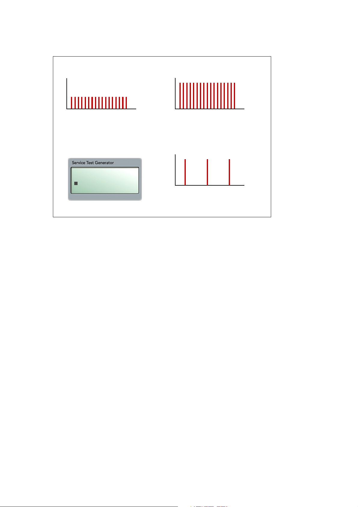
Single pulse sends a steady signal where you can select the pulse magnitude in
dBsv and the pulse rate in pulses per second (Hz).
STD pulse is the realistic testing mode. It sends a train of pulses with various
amplitudes, resembling a proper bearing signal. You can select one of 3 ampli-
tude settings and change the pulse rate in Hz.
Transd: 42000
Single Pulse
STG-Pulse
TLT Test
Transducer:
Select TMU, yes (42000) or no (40000)
Single pulse:
Train of pulses with 1 amplitude
STG pulse:
Train of pulses with mixed amplitudes
TLT test:
Recognize TMU, yes or no
Single pulse:
Set amplitude (dB) and
frequency of occurrence (Hz)
STG pulse:
Select amplitudes (3 dB ranges),
set frequency of occurrence (Hz)
dBsv
Hz
dBsv
Hz
6 STG-02 – Service Test Generator
SPM Instrument AB •Box 4 •SE-645 21 Strängnäs •Sweden Technical data are subject to change without notice.
Single pulse
The frequency range is 0 Hz to 1080 Hz. The standard test setting is 1000 Hz.
The amplitude range is 0 to 76 dBsv for the transducer setting 40000, and 0 to 96
dBsv for the transducer setting 42000.
At 0 Hz, there is of course no outgoing pulse, so the instrument should return its
”no signal”message.
At 1000 Hz, dBm and dBc (LR and HR) should both show the set dB value. At low
frequency levels, you might get a correct dBm (LR) result while dBc (HR) still show
the min. value: the pulse occurrence rate is too low to measure a carpet.
The recommended procedure is to keep the frequency at 1000 Hz and vary the
amplitude value in dBsv. Getting a result where dBm and dBc (LR and HR) differ
by 1 or 2 is normal in the low amplitude range.
Keep the frequency at 1000 Hz
Effect of lowering the frequency
SHOCK PULSE
Freq: 1000.0 Hz
Ampl: 30.0 dB
Single pulse mode
Vary the amplitude (dB)
dBsv
Hz
25 dB
dBsv
Hz
60 dB
dBsv
Hz

STG-02 – Service Test Generator 7
SPM Instrument AB •Box 4 •SE-645 21 Strängnäs •Sweden Technical data are subject to change without notice.
STG pulse
Calibration tests are made in STG pulse mode. There are three patterns with
fixed amplitude values for dBm/dBc (LR/HR). Mark your choice with SET and
press ENT to start pulse generation.
Depending on the tested instrument, it should show a dBm and a dBc value with
a delta value of 10 dBsv, or a LR and a HR value with a delta value of 10 dBsv.
You can alter the dBc and the HR values individually within the 10 dBsv delta.
Example: Setting 2 has a fixed dBm = 50 and a default dBc = 40. Using UP/
DOWN, you can set the dBc to any value between 40 and 50. Use SET to go to
the HR setting if you want to change that.
The frequency range can be set between 0 Hz and 1080 Hz. The test setting is
1000 Hz.
STG pulse menu
STG Shock pulse pattern
dBsv
Hz
dBm dBc LR HR
1: 75 65 70 60
2: 50 40 45 35
3: 25 15 20 10
STG pulse, level 2
dBm dBc LR HR
2: 50 40 45 35
Frequency: 1000.0
Select amplitude setting
with SET, press ENT
Test with all settings available
on the STG pulse menu.
Frequency = 1000 Hz

8 STG-02 – Service Test Generator
SPM Instrument AB •Box 4 •SE-645 21 Strängnäs •Sweden Technical data are subject to change without notice.
Vibration mode
To test an instrument, connect its VIB input to the VIB output of the STG-02. In
vibration mode, the STG-02 sends one of two signals:
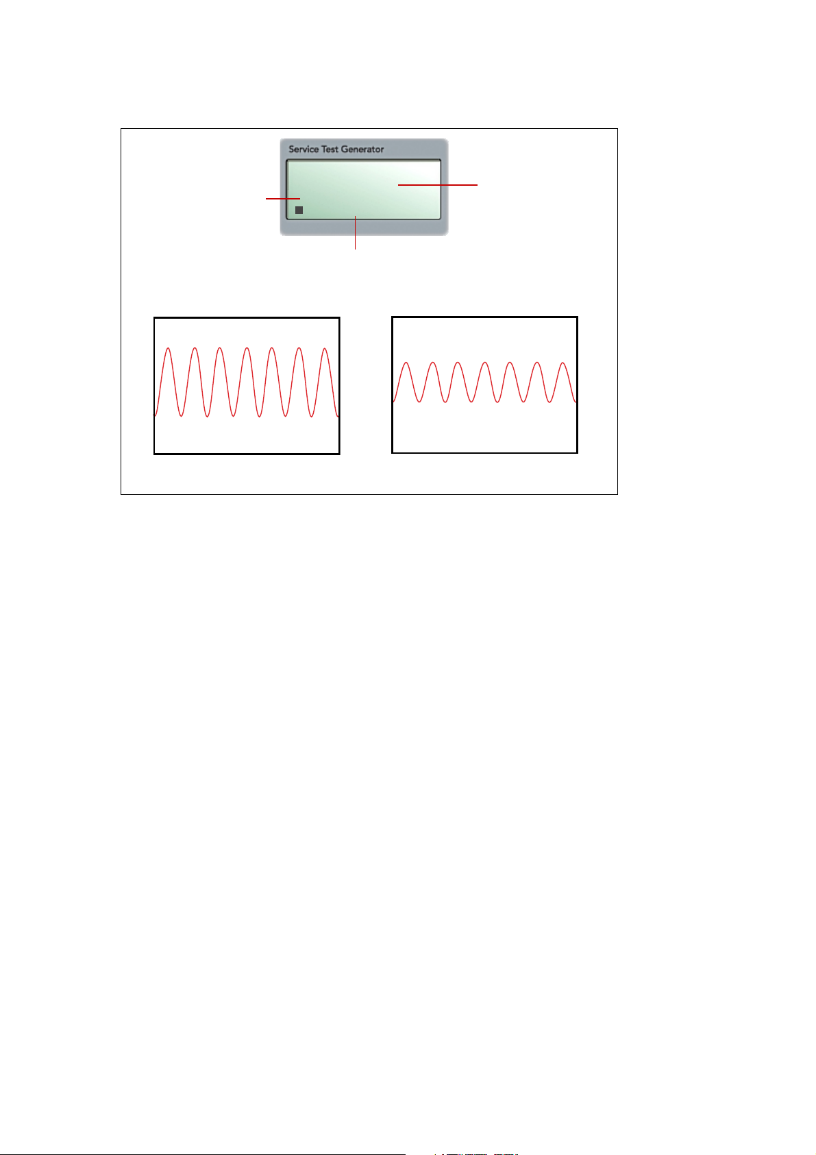
Single frequency is a single frequency sine wave with adjustable amplitude.
There are 16 choices from min. 2 Hz to max. 8000 Hz..
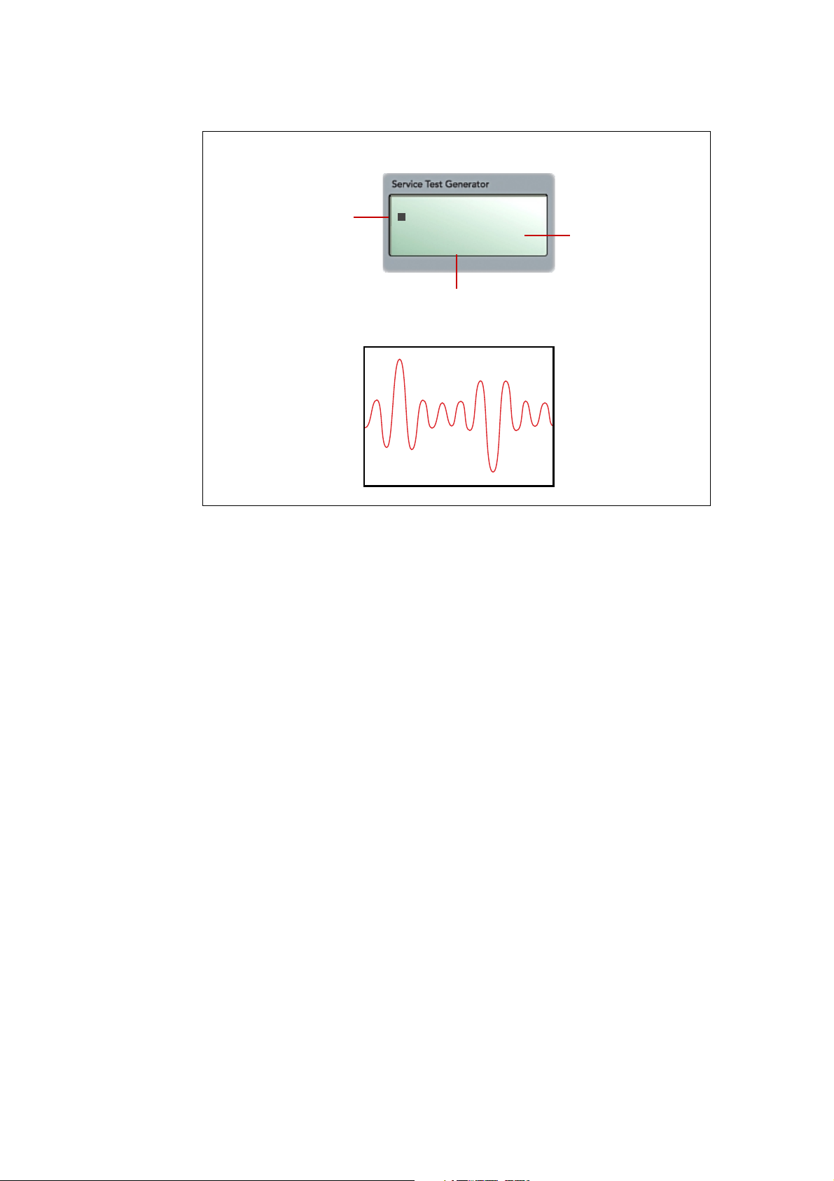
Mixed frequency is a wave containing 5 frequencies. In the low range is contains
100, 300, 500, 700, and 900 Hz, in the high range 500, 1500, 2500, 3500, and
4500 Hz. The amplitude is adjustable.
Transducer is a multiple choice line for selecting the SPM vibration transducer
which is to be simulated: TRV-01, TRV-12, TRV-18, TRV-20, or TRV-22. These
transducers have different outputs (charge, voltage, current) and measure differ-
ent quantities (velocity, acceleration). The STG-02 output corresponds to the
transducer‘s nominal sensitivity.
In addition, there are 6 adjustable transducer settings: 2 for acceleration in m/s2
(voltage), 2 for velocity in mm/s (voltage), and 2 for acceleration in pC/m/s2. You
can adjust the nominal sensitivity and the bias voltage. These transducer simulations
can be used to test VCM-20 if it is operated with ICP transducers, or instruments
from other manufacturers.
Transducer selection:
Transducer output (charge, voltage,
current), measured quantity (velocity,
acceleration, displacement) and nominal
sensitivity.
Single frequency:
One of 16 selectable frequencies,
min. 2 Hz, max. 8000 Hz.
Adjustable amplitude
Mixed frequencies:
Signal containing 5 frequencies,
low range from 100 to 900 Hz,
high range from 500 to 4500 Hz.
Adjustable amplitude
VIBRATION MENU
Tra: TRV-01/22
Single freq.
Mixed freq.

STG-02 – Service Test Generator 9
SPM Instrument AB •Box 4 •SE-645 21 Strängnäs •Sweden Technical data are subject to change without notice.
VIBRATION MENU
Tra: TRV-01/22
Single freq.
Mixed freq.
SPM transducer
Select with UP/DOWN.
No settings for SPM transducers,
continue with SET.
1: V.m/s2
Sens: 100.0 mV/m/s2
DC: 5.0 Volt
Free transducer
1 to 6. Select with UP/DOWN.
Output 1: V. = voltage,
m/s2 = acceleration.
Press ENT to adjust.
Sens: Set nominal sensitivity.
DC: Set bias voltage.
Press ESC for Vibration menu,
continue with SET.
VIBRATION MENU
Tra: 1: V. m/s2
Single freq.
Mixed freq.
Transducer selection
The active transducer has to match the transducer type used with the instrument
to be tested. After selecting an SPM transducer with UP/DOWN, press SET to
select the signal type, then ENT to start sending.
Please note that only the M8 version number for the SPM transducers is displayed
(e. g. TRV-12 but not TRV-13 with UNF threads). There is no electric difference
between TRV-10/11, TRV-12/13, TRV-18/19, TRV-20/21 or TRV-22/23. TRV-01
and TRV-22/23 have the same output and sensitivity and are thus displayed as a
single choice.
The 6 choices of customer defined transducer signal allow you to test instru-
ments from other manufacturers or to simulate an ICP transducer used with VCM-
20. These signal must be configured.
There are two each of the 3 different output types:
•acceleration measured in m/s2 and output in mV
•velocity measured in mm/s and output in mV
•acceleration measured in m/s2 and output in pC (charge).
Under Sens, you set the nominal sensitivity, under DC the bias voltage.
Press ESC to get back to the vibration menu. Press SET to select the signal type,
then ENT to start sending.
10 STG-02 – Service Test Generator
SPM Instrument AB •Box 4 •SE-645 21 Strängnäs •Sweden Technical data are subject to change without notice.
SINGLE FREQ.
Freq: 800 Hz
Velo: 08.5 mm/s
Sens: 10.0 pC/m/s2
Synchronize with the
tested instrument
Mark with Left, select
VEL, ACC or DISP
with UP/DOWN
Change frequency
and amplitude
values with
UP/DOWN
Single frequency mode
Before you start testing, you either adjust the transducer frequency setting of the
tested instrument to the sensitivity of the STG-02 or the other way round. Both
instrument must have the same nominal frequency setting.
The vibration amplitude can be shown as velocity (VEL), acceleration (ACC), or
displacement (DISP). Go to the line with SET, press LEFT to move the cursor to
the beginning of the line, then change with UP/DOWN.
When testing, you use various combinations of frequency and amplitude set-
tings. Please note:
•The set frequency has to be within the max. frequency range of the tested
instrument.
•The total output effect of the STG-02 is limited, which makes frequency and
amplitude settings interdependent. Thus, the highest frequency for the max.
amplitude output of 50 mm/s is 2 kHz, and at the max. frequency of 8 kHz
the amplitude is limited to 12 mm/s (transducers TRV-01 and TRV-22/23).
The frequency / amplitude relationship is also affected by the selected
transducer type. In practise, the STG-02 will simply stop to increase a
frequency or amplitude value when the limit is reached.
STG-02 – Service Test Generator 11
SPM Instrument AB •Box 4 •SE-645 21 Strängnäs •Sweden Technical data are subject to change without notice.
MIXED FREQ.
Freq: LOW
Velo: 12.5 mm/s
Sens: 10.0 pC/m/s2
Select LOW or HIGH
with UP/DOWN Change
amplitude values
with UP/DOWN
Synchronize with the
tested instrument
Mixed frequency mode
In mixed frequency mode, you can choose between two frequency settings:
LOW: 100, 300, 500, 700, 900 Hz
HIGH: 500, 1500, 2500, 3500, 4500 Hz.
The max. frequency has to be within the frequency range of the tested instru-
ment.
Low gives you the full amplitude range of 50 mm/s to test, HIGH a max. ampli-
tude of 18.5 mm/s (transducers TRV-01 and TRV-22/23). The vibration amplitude
is only shown as velocity (VEL).
When testing, you vary the amplitude settings. Instruments with EVAM capacity
(e. g. T30 / A30 Expert in ”analysis”mode) should find all frequencies in the mix.
Due to the FFT mathematics, they will list other frequencies but show their
energy level as 0 or close to zero.

12 STG-02 – Service Test Generator
SPM Instrument AB • Box 4 • SE-645 21 Strängnäs • Sweden Technical data are subject to change without notice.
Tel +46 152 22500 • Fax +46 152 15075 • [email protected] • www.spminstrument.se © SPM 2002-03 71689.B
Test recommendations
The following recommendations for testing SPM devices with the help of the
STG-02 are not calibration instructions. The stated tolerances are set with regard
that such test are made in an uncontrolled environment under uncontrolled con-
ditions.
General
• Synchronize the transducer sensitivity setting of STG-02 and the tested
device.
• Use a low noise cable (SPM 90176-L or 90292-L), especially on the vibration
output.
A30/T30
SPM test with 42000 transducer, STG pulse mode 2, frequency 1000 Hz.
Tolerance ± 2 dBsv.
TLT test with 40000 (response ”TRA”) and 42000 (response ”TMU”) transducers.
Before testing, set TLT to ON. The instrument should display a TLT quality value
of or greater than 20.
VIB test with TRV-01 or TRV-22 transducer, sensitivity 10.0 pC/m/s2. 10 mm/s
plus 30 mm/s at 80 Hz. Tolerance ± 1 mm/s.
A2011/T2001
As A30/T30, except: frequency 1080 Hz, no TLT test.
MG-4
Check the MG-4 specifications (label on top of the casing).
VIB channels with either transducer TRV-18, sensitivity 1.2 mV/m/s2or transducer
TRV-20, sensitivity 3.5 mV/m/s2, depending on type.
For frequency range 3 (10) to 1000 Hz, single frequency mode at 45 mm/s, 80 Hz.
For frequency range 100 to 1000 Hz, single frequency mode at 45 mm/s, 400 Hz.
Tolerance ± 1 mm/s.
SPM test with either 40000 or 42000 transducer, depending on type. Single pulse
mode at 40 dBsv, frequency 1000 Hz. Tolerance ± 2 dBsv.
TLT test with either 40000 or 42000 transducer, depending on type. The instru-
ment should display a TLT quality value of or greater than 20.
BMM-40/42 and BDM-40/42
Connect BMM to a display unit. For both BMM and BDM, TLT test must be off.
Set the jumper that disables the TLT test over both pins (upper right hand corner
of the circuit board).
SPM test with either 40000 or 42000 transducer, depending on type. Single pulse
mode at 40 dBsv, frequency 1000 Hz. Tolerance ± 2 dBsv.

STG-02 – Service Test Generator 13
SPM Instrument AB •Box 4 •SE-645 21 Strängnäs •Sweden Technical data are subject to change without notice.
VMM-14/20, VMM-15/21, VDM-14/20, VDM-15/21
Connect VMM to a display unit.
VIB test with TRV-18 transducer, sensitivity 1.2 mV/m/s2. 30 mm/s at 80 Hz.
Tolerance ± 1.5 mm/s.
BMS measuring unit
Set the TLT alarm value to 0 in Condmaster®Pro.
SPM test with 42000 transducer. Use single pulse mode at 40 dBsv, frequency
1000 Hz. Tolerance ± 2 dBsv.
VCM-20
VIB test with TRV-20 transducer, sensitivity 13.5 mV/m/s2. 30 mm/s at 80 Hz.
Tolerance ± 1.5 mm/s.
VIB-10A
VIB test with TRV-12 transducer, sensitivity 12.0 pC/m/s2. 30 mm/s at 80 Hz.
Tolerance ± 1.5 mm/s.
VIB-10B
VIB test with TRV-22 transducer, sensitivity 10.0 pC/m/s2. 30 mm/s at 80 Hz.
Tolerance ± 1.5 mm/s.
VIB-20
This test is for VIB-20 in normal configuration. In case of problems with special
versions, please contact SPM.
VIB test with TRV-01 transducer, sensitivity 10.0 pC/m/s2. 30 mm/s at 80 Hz.
Tolerance ± 2 mm/s.
BAS-10
Set the BAS-10 to ”continuous reading”.
SPM test with 4000/42000 transducer, STG pulse mode 2, frequency 1000 Hz.
Tolerance ± 2 dBsv.
TLT test with 40000 (response ”TRA”) and 42000 (response ”TMU”) transducers.
The instrument should display a TLT quality value of or greater than 20.

14 STG-02 – Service Test Generator
SPM Instrument AB •Box 4 •SE-645 21 Strängnäs •Sweden Technical data are subject to change without notice.
Technical specifications
Shock pulses
Simulated transducers: SPM 40000, SPM 42000 (with TMU)
Pulse repetition frequency: 0.1 to 1080.0 Hz
Pulse amplitude: -9 to 76 dBsv for transducer SPM 40000
-9 to 96 dBsv for transducer SPM 42000 (TMU)
Resolution: 0.1 Hz and 0.5 dBsv
Accuracy: ± 0.25 dBsv for output >5 dBsv
± 1 dBsv for output < 5 dBsv
TLT test: TMU recognition and TLT value
Vibration
Simulated transducers: SPM TRV-01, TRV-12, TRV-18, TRV-20, TRV-22
Adjustable simulation: 2 settings for velocity in mm/s (voltage),
2 settings for acceleration in m/s2(voltage),
2 settings for charge in pC/m/s2
Single frequency, choices: 2, 4, 8, 10, 20, 40, 80, 100, 160,
200, 400, 800, 1000, 2000, 4000, 8000 Hz
Mixed frequencies, low: 100, 300, 500, 700, 900 Hz
Mixed frequencies, high: 500, 1500, 2500, 3500, 4500 Hz
Velocity output: Dependent on simulated transducer, transducer
sensitivity and selected frequency.
Max. 0.5 to 50 mm/s
Resolution: 0.1 mm/s
Accuracy: ± 0.025 mm/s + 0.5 % of displayed value for
frequencies >40 Hz (valid for SPM transducer
simulation)
Instrument specifications
Temperature range: 0 °C to 50 °C (32 °F to 120 °F)
Power supply: 6 x 1.5 V LR6 alkaline cells
Power consumption: 40 to 66 mA
Size: 255 x 105 x 60 mm (10 x 4.2 x 2.4 inch)
Weight: 0.85 kg (1.9 lb)
Casing/protective cover: ABS/polyurethane
Key pad: Sealed membrane
Display: LCD, 4 x 16 characters, back light
It is recommended to calibrate the STG-02 once per year at the SPM facilities in
Strängnäs, Sweden.

STG-02 – Service Test Generator 15
SPM Instrument AB •Box 4 •SE-645 21 Strängnäs •Sweden Technical data are subject to change without notice.
Copyright
Copyright © 1999 by SPM Instrument AB, Strängnäs, Sweden. All rights reserved.
Contents of this publication may not be reproduced in any form without written
permission of SPM Instrument AB.
Patent Protection
The instruments covered by this instruction manual may be protected by one or more
Swedish or international patents or patent applications. Information provided upon
request from SPM Instrument AB, Box 4, SE-645 21 Strängnäs, Sweden.
Licences and Trademarks
SPM®, EVAM®and Condmaster®are registered trademarks of SPM Instrument AB, Swe-
den.
A30 and T30 are trademarks of SPM Instrument AB.
The separate licence agreement for CONDMASTER®users stipulates the conditions for
the use of the software.
Windows and Windows 95 are registered trademarks of Microsoft Corporation, USA.
Warranty and Responsibility
The warranty for the instrument is applicable as soon as SPM Instrument AB has received
the signed warranty form from the possessor of the instrument.
SPM Instrument AB reserves the right to make alterations of the contents in this Instruc-
tion Manual at any time without notice. SPM Instrument AB does not take any responsibil-
ity for the contents in this manual.

16 STG-02 – Service Test Generator
SPM Instrument AB •Box 4 •SE-645 21 Strängnäs •Sweden Technical data are subject to change without notice.
Table of contents
Other SPM Test Equipment manuals

Popular Test Equipment manuals by other brands


MULTI MEASURING INSTRUMENTS CO.,LTD.
MULTI MEASURING INSTRUMENTS CO.,LTD. MCL-800IRV instruction manual

Extech Instruments
Extech Instruments ExStik PH150-C user guide

Mastech
Mastech KPS-TL300 instruction manual

Mastech
Mastech MS7220 quick start guide

Pintek
Pintek DP-16V instruction manual

MSA
MSA galaxy GX2 Quick Start Guide-Description and Setup


