Besantek BST-GFL31 User manual

BST-GFL31 User Manual
1
Catalog
1. ABOUT BST-GFL31
........................................................................................................................................ 2
1.1 BST-GFL31 Brief Information?............................................................................................................... 2
1.2 BST-GFL31 Main Functions................................................................................................................... 2
1.2.1 Ground Fault Location................................................................................................................. 2
1.2.2 Frequency Spectrum Analysis ..................................................................................................... 2
1.2.3 Oscilloscope ................................................................................................................................ 2
1.3 Features ................................................................................................................................................. 2
1.4 Typical Application.................................................................................................................................. 3
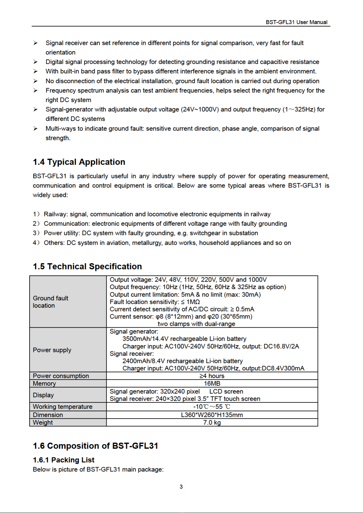
1.5 Technical Specification ........................................................................................................................... 3
1.6 Composition of BST-GFL31 ................................................................................................................... 3
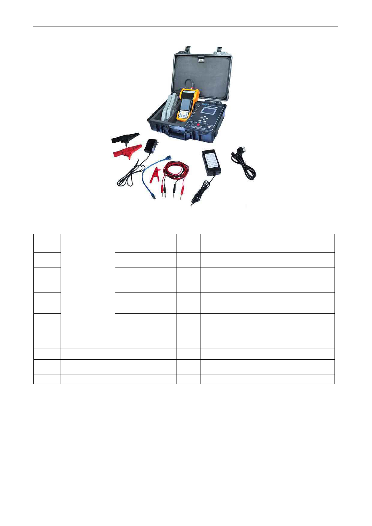
1.6.1 Packing List ................................................................................................................................. 3
1.6.2 BST-GFL31 Main Body ............................................................................................................... 4
1.6.3 Signal Receiver ........................................................................................................................... 5
1.7 Basic Concepts ...................................................................................................................................... 6
1.7.1 About Faulty Grounding............................................................................................................... 6
1.7.2 Wire Mix-connection.................................................................................................................... 7
1.7.3 Short circuit.................................................................................................................................. 8
1.7.4 Current leakage ........................................................................................................................... 8
1.7.5 Tracing of Current Signal............................................................................................................. 8
2. MAIN OPERATION OF BST-GFL31 ............................................................................................................... 8
2.1 General Steps for Fault Location ........................................................................................................... 8
2.2 Operation Preparation............................................................................................................................ 9
2.3 Wire connection with DC System........................................................................................................... 9
2.4 Set Generator Output Signal................................................................................................................ 10
2.4.1 Measurement of Circuit ............................................................................................................. 10
2.4.2 Output Signal Adjustment.......................................................................................................... 11
2.4.3 Output Signal to Circuit for Fault Location ................................................................................ 12
2.4.4 Return Circuit for Fault Location................................................................................................ 13
2.5 Signal Tracing with Signal Receiver..................................................................................................... 13
2.5.1 Frequency Synchronization....................................................................................................... 13
2.5.2 Set Signal Reference ................................................................................................................ 14
2.5.3 How to Locate Ground Fault? ................................................................................................... 17
2.6 Some Tips for Ground Fault Location .................................................................................................. 18
2.6.1 Multiple Setting of Signal Reference ......................................................................................... 18
2.6.2 Gross searching ........................................................................................................................ 20
2.6.3 Use more than one signal receiver............................................................................................ 20
2.7 Signal Changes in Earth Fault Circuit .................................................................................................. 20
2.8 Location for Other Ways of Fault ......................................................................................................... 21
2.8.1 Wire Mix-connection.................................................................................................................. 21
2.8.2 Short-circuit Fault Location........................................................................................................ 22
2.9 About Distributed Capacitance............................................................................................................. 22
3. OTHER SETTINGS OF GENERATOR AND RECEIVER ............................................................................. 23

BST-GFL31 User Manual
2
3.1 Signal Generator Setting...................................................................................................................... 23
3.1.1 Set Date & Time ........................................................................................................................ 23
3.1.2 Parameter Setting...................................................................................................................... 23
3.1.3 Firmware Version....................................................................................................................... 24
3.2 Signal Receiver Functions and Settings .............................................................................................. 24
3.2.1 Frequency Spectrum Analysis ................................................................................................... 24
3.2.2 Oscilloscope .............................................................................................................................. 26
3.2.3 System Setting .......................................................................................................................... 26
4. SERVICE & MAINTENANCE ........................................................................................................................ 28
4.1 Self-Check............................................................................................................................................ 28
4.2 FAQ ...................................................................................................................................................... 29
4.3 Cleaning & Storage .............................................................................................................................. 30
4.3.1 Cleaning .................................................................................................................................... 30
4.3.2 Storage ...................................................................................................................................... 30
5. CONTACT BESANTEK ................................................................................................................................. 30

▲Safety Information
For your protection, please read this safety information completely before operating the locator. Carefully
observe all warnings, precautions and instructions.
WARNING: Service information described in this manual is to be done by qualified personnel only. To
avoid electrical shock or equipment damage, do not service the instrument unless you are qualified and
with BESANTEK’s instruction.
DANGER
Safety testing has been done on this instrument thoroughly
before shipment. However, mishandling during use could
result in injury or other bad consequences, as well as damage
to the instrument. Make sure that you understand the
instructions and precautions in the manual before use. We
disclaim any responsibility for accidents or injuries not resulted
directly from instrument defects.
Safety Symbols
Description of symbols used in this manual.
WARNING Indicates correct operation to prevent a significant hazard that
could result in serious injury or other bad consequences to
users or instrument.
NOTE Indicates advisory items related to performance or correct
operation of the instrument.
▲Operating Precautions
To avoid electrical shock or fire, read these precautions first before using the locator:
Except as explained in this manual, do not attempt to service this equipment yourself.
Do not operate the equipment around explosive gas or vapor.
Only use BESANTEK’s testing leads and other relative accessories with the locator.
Before use, inspect the locator, testing leads and other accessories for mechanical damage and
replace if necessary. Pay special attention to the insulation surrounding the connectors.
Remove all clamps, testing leads and accessories that are not in use.
Do not apply the instrument in other purposes that are not described in this user manual
Ensure the equipment is provided with adequate ventilation.
This manual describes the general operation of the testing system. If your system has features or
accessories not addressed in this manual, please contact your supplier.
Only qualified technicians are allowed to use the equipment. For fast ground fault location, it will be
very important and necessary to familiarize the tested environment, especially the wiring structure of
the target site.
Test Equipment Depot - 800.517.8431 - 99 Washington Street Melrose, MA 02176
TestEquipmentDepot.com

BST-GFL31 User Manual
2
1. ABOUT BST-GFL31
1.1 BST-GFL31 Brief Information?
BST-GFL31 is BESANTEK’s new generation of ground fault locator applied with advanced technique
for earth fault detection. This patent-protected product is built based on years of field experience in
different DC systems. It specially deals with current leakage in DC system of high grounding resistance
below 1MΩ. Without switching off the DC system, it pinpoints faulty grounding online where electrical
lines have breakage and current lost to the ground. It gives excellent solutions for troubleshooting and
preventative maintenance.
Compact and rugged design makes the BST-GFL31 easy to use in small places and harsh environment.
1.2 BST-GFL31 Main Functions
1.2.1 Ground Fault Location
With comprehensive ways including signal strength, phase change and precise judgment for leakage
current direction, it fast pinpoints ground fault.
Based on different distributing capacitance, it selects the right output frequency for testing, which
enables it to be widely used in different DC systems.
Output voltage of signal generator:
selectable among 24V, 48V, 110V, 220V, 500V and 1000V. This will meet requirement for various
electric circuit of different voltage levels without interference to the circuit.
Output current of signal generator:
5mA and unlimited current (limited power with max output current of 30mA). It is selected as per
different systems, preventing from incorrect operation of circuit relay.
Output frequency of signal generator: Standard 10Hz and with options of 1.0Hz, 50Hz, 60Hz and
325Hz which are selectable based on different DC systems.
1.2.2 Frequency Spectrum Analysis
It effectively analyzes the working signal and surrounding interferences signals of DC system. This will
help to select the right output frequency for ground fault location and avoid interference by the
surrounding signals.
1.2.3 Oscilloscope
It checks waveform of target signal.
1.3 Features
Patented technology, pinpoint current leakage fault with grounding resistance lower than 1MΩ
Innovative dual-clamp for signal receiver, each clamp has two sizes of opening jaw for different
conductors
One pair of clamp working together, effective cancel capacitive interference when system is online
Precise current direction (positive or reversed) indicating for leaking current help fast locate the
faulty grounding
Adjustable output frequency on signal receiver effectively avoids interference from DC system itself


BST-GFL31 User Manual
4
Fig. 1.6.1
Full packing list:
Item Parts No. NOTE
1
Main body
(in molding
case)
Signal generator 1
2 Power adaptor 1
Input: AC110V/220V
Output:16.8VDC/2A
3 Signal testing lead 2 One red and one black
2.5m long each
4 Alligator clip 2 One red and one black
5 Puncture clip 1 Red
6
Standard signal
receiver
Signal receiver 1
7 Dual-range
current detector 2 One pair, dual-range (φ8 and φ20)
With 150cm long lead
8 Power adaptor 1
Input: AC110V/220V
Output: 8.4VDC/300mA
9 User manual 1 This manual
10 USB drive 1 With backup firmware, software and user
manual
11 Qualification certificate 1
1.6.2 BST-GFL31 Main Body
Below is picture of BST-GFL31 main body and functionality of each part.
Test Equipment Depot - 800.517.8431 - 99 Washington Street Melrose, MA 02176
TestEquipmentDepot.com

BST-GFL31 User Manual
5
Fig 1.6.2.1
After turning on the On/Off switch, press any key on the keypad to continue and you will see the main
menu as below for each function. Use the arrow keys to highlight each and press ENT to confirm the
selection or press Esc to go back. Main body function and setting will be introduced in detail in this
manual later.
Fig 1.6.2.2
1.6.3 Signal Receiver
All standard units will come with standard signal receiver and one pair of dual-range current detector.
Signal Receiver Main Body:
Back Side

BST-GFL31 User Manual
6
Bottom Topforcurrentdetector
Fig1.6.3
Standard signal receiver could be operated by touch screen, keypad or quick navigation keys at side.
After switching on the unit, you will see the main functions including ground fault location, frequency
spectrum analysis, oscilloscope and system setting. We will introduce these functions in detail in the
following context.
Current Detector:
Fig1.6.3.1 Fig 1.6.3.2 Current detectors
Signal receiver main body will be connected with one pair of dual-range current detector like Fig 1.6.3.1.
BESANTEK’s innovative designing of dual-range current detector (CT) has 2 different sizes of opening
jaw (8*12mm and 30*65mm). Depending on different size of wire or conductors, you could selectively
clamp with either size of jaw which have the same effect.
Also, with one pair of current detectors working at the same time in the circuit, BST-GFL31 will have
strong capability for anti-interference. Therefore, it could check ground fault effectively even when
system is online without switching off the DC system.
Each current detector has labels of arrow mark at both sides. The arrow marks are used for current
direction indication during ground fault location. For detailed operation instruction of dual-range current
detector, please refer to Section “2.5 Signal Tracing with Signal Receiver”.
1.7 Basic Concepts
1.7.1 About Faulty Grounding
AC or DC power systems are generally insulated to the ground in railway electric works, power
substation, telecom base station and the alike. There are also clear and strict rules for insulating
resistance in different voltage levels of AC or DC power systems.
And it is generally considered as the phenomenon of faulty “Grounding” when grounding resistance of

BST-GFL31 User Manual
7
one point (or multi-points) becomes lower than tolerance value. Take following chart for example, Point A
is the grounding point, R is the grounding resistance, C1 and C2 indicate distributed capacitances before
and after the malfunction point.
Fig 1.7.1
When one point of circuit has unwanted grounding like this, protection equipments, signaling equipments
and automation equipments may have incorrect operation or may stop running, or fuse will burn out and
thus cut off power supply for protection equipments, automation equipments, controlling circuit and
communication signaling system.
If one point problem is unsolved for long time until more points have the same problem, it may damage
electronic circuit or equipments. Therefore, unwanted grounding of electronic circuit is very big hidden
danger. Therefore, a fast detection of ground fault will be very necessary before “small” problem
becomes big accident.
1.7.2 Wire Mix-connection
Sometimes two or more groups of power systems are working simultaneously, and normally they are
insulated from each other. When insulating resistance between these individual powers become lower
than required value in one point or more points, we call it as “wire mix-connection”. Below is one
example. Point A and B are malfunction points. R indicates the mix-connection resistance. C1 and C2
indicate the distributed capacitances.
Wire mix-connection is common problem in signaling system in railway. It also has big hidden hazard like
faulty grounding.
Fig 1.7.2

BST-GFL31 User Manual
8
1.7.3 Short circuit
One power system generally comes with several loads working together at the same time. Normally
when all loads are disconnected, power output current becomes O Amps. However, when insulating
values of one point or more are lower than requirement but there is still current flow, we call it as “short
circuit”. In this case, positive busbar is short-circuited to negative busbar.
Short circuit will increase power consumption and may even burn up power supply and cause other bad
accidents like faulty grounding.
1.7.4 Current leakage
Circuits, which are normally insulated to the ground, have current flow to the ground due to bad
insulation or circuit distributing capacitance.
1.7.5 Tracing of Current Signal
When we are using the BST-GFL31 to locate the faulty grounding, signal generator (main unit) will send
a “current signal” in certain frequency to the circuit. This current signal will flow in the circuit. With a
signal receiver (connected with a current detector), we will trace the current signal in different points of
the circuit. In comprehensive ways of signal judgment like current direction, signal strength and phase
angle, we will fast locate the ground fault.
For detailed ways to pinpoint the faulty grounding, we will introduce in Chapter 2 below.
2. MAIN OPERATION OF BST-GFL31
2.1 General Steps for Fault Location
For ground fault location, we will generally follow these steps:
1) Measurement preparation
Familiarize with the wiring structure of DC system and judge which line has faulty grounding.
It is very important to know the wiring structure on how the wires are connected in the DC system.
This will help you fast trace the ground fault.
2) Connect the signal generator with DC system.
When positive busbar has ground fault, connect red testing lead with positive busbar and black lead
with ground. When negative busbar has fault, connect black lead with negative and red lead with
ground.
3) Set output signal in signal generator and set signal mode as “Continue”.
Signal generator will test output voltage, current and grounding resistance.
4) Do frequency synchronization in receiver
5) Proceed with “Reference setting” in signal receiver
6) Follow the theory of ground fault location to pinpoint the faulty grounding one by one.
7) Make a record for the signal strength for each branch for signal comparison afterwards. If necessary,
set the reference several times for better comparison.
8) Solve the problem of faulty grounding as per requirement.
Here, we will explain deeper for each step.

BST-GFL31 User Manual
9
2.2 Operation Preparation
You are suggested to prepare well as below before going to the filed for earth fault tracing::
1) Make sure that both BST-GFL31 signal generator and receivers are fully powered. Signal generator
can work with power adaptor connecting with AC power supply.
2) Familiarize with onsite wiring for target DC system. It will be very important and helpful to have the
detailed wiring instruction indicating how each equipment is connected in the whole DC system.
3) For security purpose, please wear helmet, insulation-protected gloves and other protecting facilities
during operation.
4) Judge which busbar has faulty grounding:
A. DC circuit:
Use a multi-meter, switch to DC voltage measurement mode, and respectively measure the voltage
between busbar (negative and positive) and ground. Normally both absolute values should be equal
(around half of nominal voltage). If one of the voltage values is lower, this busbar should have faulty
grounding.
B. AC circuit:
Switch the multi-meter to AC voltage testing mode and respectively test the voltage value between
each power line (phase line and null line) and ground. Normally both absolute values should be the
same. If one of the voltage values is lower, that line should have earth fault.
5) Connect testing leads with signal generator and current detectors with signal receiver.
2.3 Wire connection with DC System
Fig 2.3.1
First connect the testing leads with signal generator, red lead with red socket and black lead with black
socket (Fig 2.3.1). Make sure that they are not mixed up. Then connect other ends of the leads with
alligator clips. After correct judgment on which busbar has ground fault, connect the testing leads with
the DC system as below:
1) If positive busbar has ground fault, connect red lead with positive busbar and black lead with ground.
Fig 2.3.2 Fault on positive busbar

BST-GFL31 User Manual
10
2) If negative busbar has fault, connect black lead with negative and red lead with ground.
Fig 2.3.3 Fault on negative busbar
Drawings of current clamp in thesetwo circuit diagrams are for your reference only. We will explain for
their operation in detail in coming context.
Note: If there is no conductor in busbar to connect the testing clip for signal injection, you are suggested
to use the red puncture clip to pierce the insulated cable.
2.4 Set Generator Output Signal
2.4.1 Measurement of Circuit
After the signal generator is well connected with the DC circuit, please turn on the unit, you will see the
main screen as Fig 2.4.1.1. Use arrow key to highlight “Ground Fault” and press ENT to select it. You
will go to the next screen for output signal setting like Fig 2.4.1.2.
Fig 2.4.1.1 Fig 2.4.1.2
You will need to set the output voltage and output current. Their setting will be:
Output Voltage:
Optional among 24V, 48V, 110V, 220V, 500V and 1000V. Generally the selected output voltage
should be same or one level higher than system voltage. For example, if it is DC110V substation,
then please select 110V or 220V as output voltage.
Output Current limit:
Has options of “5mA” and “UL” (unlimited).
Current limit of 5mA means that the signal generator will output a signal with maximal current of
5mA. Based on different circuit signals, output current will be adjusted automatically up to 5mA.
In the condition of “UL”, it will be based on limited output power (5w) with maximal output current
of 30mA.

BST-GFL31 User Manual
11
Warning!
To avoid unwanted operation of relay in the DC system, please select current limit properly. In
signaling circuit of railway station, over 5mA output current will cause unwanted operation of relay.
In such circumstances, you are suggested to select 5mA. Otherwise, you are always suggested to
select “UL” (limited power) to maximize the signal for faster signal tracing.
Select output voltage level and current limitation and click Next to continue. The signal generator will
have an initial measurement for distributed capacitance(C), output current(I) and grounding resistance(R)
(Fig. 2.4.1.3). Display of waveform is in square wave. The waveform indicates output voltage (blue) and
current (red) of signal generator. Numbers (e.g. 219 56 200 in Fig 2.4.1.3) above the waveform indicate
respectively maximal, average and minimal sampling value of voltage and current.
Note:
For definition of distributed capacitance and its relationship with resistance and frequency, please
refer to “2.9 About Distributed Capacitance”.
Fig 2.4.1.3
2.4.2 Output Signal Adjustment
The initial measurement gives you a brief idea about the fault signal in the circuit. You may alternatively
adjust the output signal in the next screen as below by pressing button Next.
Fig 2.4.2
1) Adjustment for output voltage:
If the current signal is not strong enough (lower than 1mA) in the previous measurement, you are
suggested to increase the current signal by increasing output voltage to a higher level.
2) Adjustment for output current limitation:
Change the current limitation as 5mA or UL if necessary.
About output Frequency:
The defaulted output frequency is set as 10Hz, which makes it simpler for users’ operation. Based

BST-GFL31 User Manual
12
on BESANTEK’s years field experience, 10Hz output frequency will fit most DC systems for fast
location of earth fault. Generally it is no need to change.
If you have particular DC system that needs other output frequency, please first change the setting
in Section “3.1.2 Parameter Setting”.And also do frequency synchronization as per steps in
Section “3.2.3.1 Frequency synchronization”.
2.4.3 Output Signal to Circuit for Fault Location
After above adjustment, click Next to continue. You will see the screen like Fig 2.4.3.1 with output
voltage, current, grounding resistance and waveform. Defaulted waveform is displayed as “Continued”.
You could use arrow key to change the view as “Discontinue” which will have 1 second interval. Different
ways of display is illustrated as diagram in Fig 2.4.3.2 and Fig 2.4.3.3.
NOTE: For ground fault location, please set signal display as “Continue”.
Fig 2.4.3.1
Fig 2.4.3.2 continued waveform
Fig 2.4.3.3 Discontinued waveform
1000V on the right side of screen (Fig 2.4.3.1) indicates the output voltage. Numbers on the right column
(e.g.4 and 0 in Fig 2.4.3.1) are for BESANTEK’s R&D purpose, users can neglect it. All these numbers in
the screenshots are for reference only; they are different in different circuits.
Signal auto adjustment:
After adjustment for output signal, the output voltage may still be automatically increased or decreased
to a proper value in the screen like Fig 2.4.3.1.
This auto adjustment will help users gain better signal for ground fault location. Meanwhile, it will prevent
the signal from being too strong to damage the DC system.

BST-GFL31 User Manual
13
2.4.4 Return Circuit for Fault Location
After the above signal injection from signal generator, there will be return circuit like the exemplified
diagram below.
Supposed that the fault is on positive busbar on the point called “Fault 1”, the current signal injected from
BST-GFL31 signal generator will go all the way to the point “Fault 1”, outflow to the ground, finally goes
back the signal generator via the testing lead and thus form a return circuit.
This return circuit is important for signal tracing using a signal receiver. And this is the working principle
for BST-GFL31 Ground Fault Locator.
For detailed explanation of the theory on signal tracing, please refer to Sections from 2.5 to 2.7.
Fig 2.4.4 Example of current flow
2.5 Signal Tracing with Signal Receiver
After the above setting and measurement on signal generator, you could leave the generator alone as
long as there is enough power. Otherwise, connect the AC power adapter during operation. Then the
signal receiver will take charge of the rest work for signal tracing.
Note:
Use the signal receiver for signal tracing ONLY after the signal generator is in the last screen like
below (after signal adjustment and with “continued“ signal)
Fig 2.5
2.5.1 Frequency Synchronization
Before we start signal tracing, make sure that frequencies of signal generator and receiver are identical.
In factory default setting, both signal generator and receiver have frequency of 10Hz. In this case, you
do not need to change frequency or set frequency synchronization. Then please skip to Section 2.5.2
below.
If your signal generator has a different output frequency, please refer to “3.2.3.1 Frequency

BST-GFL31 User Manual
14
synchronization” for setting instruction.
2.5.2 Set Signal Reference
After signal receiver is connected well with current detector, turn on the receiver and select “Ground
Fault”. You will see the screen for frequency setting as below:
Fig2.5.2.1 Fig2.5.2.2
After frequency synchronization, receiving frequency 10Hz is kept unchanged. Volume setting has
option from 0 to 9. For example, if setting volume is 4, when detected signal is higher than 40%, signal
receiver will BEEP. Screenshot like below (Fig 2.5.2.3) indicates 40% signal strength.
Signal Reference Setting
This is very important step for BST-GFL31 during ground fault location.
After initial setting for receiving frequency and audio, click OK to proceed in the screen like Fig 2.5.2.3.
Before reference setting, signal strength in the screen can be any number.
Fig 2.5.2.3
What is reference setting?
When the signal generator injects a current signal into the DC circuit, this current signal can go
anywhere and finally outflow to the point of fault. Since there are too many branches and sub-branches
in real DC system, the signal will become weaker and weaker, which will make it very difficult to trace.
To make signal tracing easier, we use the term of “Signal Reference”. It will help compare different
signals more effectively to sort out the real fault.
At the start of the circuit (output of signal generator), set the reference point as 100% signal strength.

BST-GFL31 User Manual
15
Future signals will be compared against the reference point. For example, at the start of the circuit,
referred to Point A in the following diagram, its current value of 20mA is set as 100%. Down the circuit,
at Point C, its current value of 10mA will become 50%.
Fig 2.5.2.4
Reference Point setting for the first time
IMPORTANT: Please do the reference setting only AFTER signal generator is connected with the DC
circuit and injects signal properly (in the last screen like Fig 2.5).
Take Fig 2.5.2.5 for example, after signal injection, the signal at the beginning (close to red socket on
signal generator) of red testing lead is strongest. If in Fig 2.5.2.6, beginning of black testing lead will
have strongest signal. In the explanation below, we will use the first situation as example (Fig 2.5.2.5).
1) When positive busbar has fault:
Fig2.5.2.5
2) When negative busbar has fault:
Fig 2.5.2.6
For the first reference setting, please clamp only ONE of the two current detectors around beginning

BST-GFL31 User Manual
16
of red testing lead with the arrow mark (label on the clamp) pointing towards the direction of faulty
point as Fig 2.5.2.7. Keep the current detector stable for around 5 seconds and then click the button
Set Ref in the screen of signal receiver.
Fig 2.5.2.7 Correct connection Fig 2.5.2.8 Incorrect connection
After reference setting, signal strength of reference will be set as 100%, phase angle becomes 0° and
current direction will be positive (Green like ).
Below are the examples before and after reference setting. “Ref I” is the current value at the reference
point. Before setting reference, this value is always defaulted as 1.000mA.
Fig 2.5.2.6 Before setting Fig 2.5.2.7 After setting
Red columns in middle of the screen indicate strength of signal in percentage. It will increase one
column when signal increases by 10%.
NOTE:
1) Only use ONE current clamp for reference setting. Do not use two clamps.
2) Before setting, make sure to set signal as “Continue“ in signal generator (Fig 2.5).
3) Although you could set the reference for many times, please make sure to clamp in the
circuit that has current flow (before the point of fault) and with arrow pointing towards
earth fault.
4) If reference setting is done when there is no current flow at all, signal display in
receiver after the reference setting will be a misleading to you.
5) When there is fault on negative busbar, wire connection is like Fig 2.5.2.6. And in
reference setting, the current clamp should be connected with black testing lead in the
same way like Fig 2.5.2.7 (arrow mark towards the faulty point).
Test Equipment Depot - 800.517.8431 - 99 Washington Street Melrose, MA 02176
TestEquipmentDepot.com

BST-GFL31 User Manual
17
2.5.3 How to Locate Ground Fault?
After the reference setting, we will continue with the most important part for signal tracing with the help of
dual-range current clamp. Let us refer to the following diagram again:
Fig 2.5.3
Solution for Online fault tracing
In most DC systems (like power substation), it could not be shut down. So the fault tracing will be carried
out when the system is working online. In this case, there will be high interference that is generated by
distributed capacitance from the circuit itself. With BESANTEK’s dual-range current clamp, it can
effectively cancel the interference and pinpoint the fault much faster.
Steps for fault location
Take the diagram in Fig 2.5.3 for example (supposed that positive busbar has ground fault).
1) Sectionalize the DC system
After setting for the first reference point in Point a, we will sectionalize the DC system as different
“Levels”. The first level will be Branches of b, c, d, e and f. The second level will be Branch g, h, i,
j, k, l, m and n. All these branches are connected with loads which has input (red line) and output
(black line). And you could consider all cabinets in power substation as bigger loads with many
smaller loads inside.
As the earth fault is on positive busbar, the signal tracing will follow all the way based on positive
busbar. We will begin the signal search from the first level.
During the process of signal tracing, it is very important to have a detailed record about the
wiring structure on how each load is connected in the system. This will help you trace the signal
effectively.
2) Use one-clamp or two-clamp tracing
Use one clamp to clamp around input and output of the load when these two lines are very close
to each other (like Branch b, c and e in Fig 2.5.3).
Use two clamps to clamp around the input and output line of load when input and output lines
are far away from each other (like Branch d and f in Fig 2.5.3).
Note: If one load has more than one input line or output line, connect the clamp around all the
input and output lines.
One-clamp and two-clamp operation have the same purpose: to cancel the interference
generated by DC system itself. Also, the arrow mark direction (label on the clamp) should always
Table of contents
Other Besantek Test Equipment manuals

Besantek
Besantek BST-IT30 User manual

Besantek
Besantek BST-ELC06 User manual

Besantek
Besantek BST-IT706 User manual

Besantek
Besantek BST-VM04 User manual

Besantek
Besantek BST-LAN10 User manual

Besantek
Besantek BST-IT705 User manual

Besantek
Besantek BST-LT05 User manual

Besantek
Besantek BST-ELC01 User manual

Besantek
Besantek BST-ET14 User manual

Besantek
Besantek BST-ET103 User manual