Spon NBS-2301P55 User manual


0
Contents
Summary.............................................................................................................................................................................................................. 1
Safety precaution.................................................................................................................................................................................................1
Product Introduction............................................................................................................................................................................................ 2
Interface description............................................................................................................................................................................................ 2
Introduction.........................................................................................................................................................................................................3
Packing list............................................................................................................................................................................................................3
Wiring.....................................................................................................................................................................................................................4
Basic network setting.......................................................................................................................................................................................... 5
User-define terminal parameters...................................................................................................................................................................5
Login Web page................................................................................................................................................................................................... 5
Network parameters............................................................................................................................................................................................ 6
Audio parameters................................................................................................................................................................................................ 7
System parameters............................................................................................................................................................................................. 8
Web management............................................................................................................................................................................................... 8
Restarting device................................................................................................................................................................................................. 8
Resetting to defaults............................................................................................................................................................................................9
Downloading word stock.....................................................................................................................................................................................9
Upgrade firmware................................................................................................................................................................................................ 9
Basic function...................................................................................................................................................................................................10
Starting up interface.......................................................................................................................................................................................... 10
Output volume adjustment............................................................................................................................................................................... 10
Zone control........................................................................................................................................................................................................10
Calling to terminal.............................................................................................................................................................................................. 11
Terminal broadcasting.......................................................................................................................................................................................11
Local broadcasting............................................................................................................................................................................................ 11
System information............................................................................................................................................................................................12
Receive call........................................................................................................................................................................................................ 12
Receive Broadcasting....................................................................................................................................................................................... 12
Network timing task........................................................................................................................................................................................... 12
Local timing broadcast...................................................................................................................................................................................... 12
The local timing task import............................................................................................................................................................................. 12
Alarm input triggers SD card to broadcast audio..........................................................................................................................................14
Fault exclude.....................................................................................................................................................................................................14
Copyright statement....................................................................................................................................................................................... 15

IP Amplifier User Manual
1
Summary
Safety precaution
Please abide by the warning and the relevant safety tips.
Please take this manual in convenient place after you reading the guide for future reference.
Warning
The sign means there is potential safety hazard, when operate wrong may result in death or serious injury.
The sign is used to remind the user that attached is the important operation and maintenance data.
Setting and Installation
(1)Avoid being wet with the water.
Don’t make the machine or exposed to rain water or other liquid contamination of the environment, or lead to fire or get an
electric shock.
(2)Don’t use unspecified voltage.
Using the marked voltage on the machine.
Using more than the logo of voltage could lead to fire or shock.
(3)Don’t scratch the power cord.
Don’t scratch the power cord or cut it.
Simultaneous, keep the power line far way from heated objects, put heavy things on it will lead to fires or electric shock.
Using machine
(1)In case of the anomalies
Please turn off the power supply immediately when finding the abnormal phenomena, please connect with the agency. if you
continue to use, it will likely fires or shock.
·The smoke or odor of the machine.
·The inside of the machine is flooded by water or foreign bodies intrusion.
·Machine falling or machine shell damage.
·The power cord damage(wire core is exposed of broken, etc)
·Fault(eg: it can’t network, no sound ..etc)
(2)Don’t open the machine internal or modify the machine
Do not let foreign matters invade the machines internal.
Don’t let the metal items or inflammable objects inserting machine such as foreign inserting machines or throw into the vents
machines internal, otherwise will likely cause fires or electric shock.
(3)Please do not touch it when thundering
To avoid electric shock, please do not touch the machine and the plug when lightning, etc.
(4)Please do not place containers with liquid or small metal objects on machine above
If gets upset containers, and let the fluid inflow to the machine that will likely fires or cause shock.
(5)Do not open the machine internal or modify the machine
The machine internal contains high voltage parts, once open the cover or modify the machine, it will likely fires or cause shock.
All the maintenance and other machine modification should be operated by professional personnel.
(6)Maintenance and the precautions for not using in a long time
While maintenance, if the machine is not using for 10 days or more, please shut off power supply switch for safety. If do not
comply with this provision, it will likely cause electric shock or fires.

IP Amplifier User Manual
2
Product Introduction
IP amplifier with intellectual-property rights of IP Audio digital network technology. It is the part of IP network broadcasting
system, and it’s controlled by server software. It can realize the network audio terminal function.
Features
IP Network model with pre-constant voltage amplifier (100V output), the start time ≤1s.
3 pre-audio input (network audio, local line input, local MIC input), each adjust the unified the tone control way independent.
With 4.3 inch TFT color LCD, control knob.
130W、260W、360W、550W、700W can be selected.
Support local SD play and remote updated the audio file of SD card built in Nandflash clip play.
Standby power low, there is no second close parts of the supply the amplifier automatically.
Supply audio line output, extend external amplifier.
Interface description
Front
①Power switch and power indicator: turn on power and lighten the indicator, turn off power and indicator.
②LED screen display the host work information.
③Function selection button to realize the corresponding function of LED screen displayed.
④Single-button coding rotation knob: Function confirm button, function select rotation knob, adjustable audio output volume.
⑤MIC can speaker to Mic.
⑥Remote receiver module.
⑦TREBLE knob: adjust the high frequency volume which is input.
⑧AUX2 knob to adjust the volume of AUN2 line input.
⑨AUM1 knob to adjust the volume of AUX1 line input.
⑩MASTER knob: adjust the amplifier audio input volume.
⑪BASS knob: adjust the low frequency volume which is input.
⑫MIC3 knob to adjust the volume of MIC3 line input.
⑬MIC2 knob to adjust the volume of MIC2 line input.
⑭MIC1 knob to adjust the volume of MIC1 line input.
⑮MIC1: microphone input port.
⑯PEAK area: 8 way LCD level indicate function, identify the amplifier output volume.

IP Amplifier User Manual
3
Back
①MIC2、MIC3:conference MIC input interface.
②Network input interface: connect with the network switcher.
③SD card insert port: with storage timing task function.
④AUX1、AUX2 line input interface.
⑤Audio output port( line output)
⑥Alarm input / output port (3 lines alarm input port: 1-G for alarm input 1, 2-G for alarm input 2, 3-G for alarm input 3, when two
pins of a certain route are short circuit connected, the IP amplifier will automatically play the corresponding audio files in the SD
card); 2 lines alarm output port:○-NO: alarm output por in normally opent, and will be closed when it is triggered;●-NC: alarm
output port in normally open, and will be disconnected when it is triggered.
⑦100V power zone output port: COM is the common terminal of each zone. 1, 2, 3 and 4 represent 1 ~ 4 zones.
⑧The power output port: support for constant voltage 100 v, 8 ~ 16 Ω output.(note: constant voltage output and constant
resistance output can not be used at the same time).
⑨Cooling fan
⑩AC220V power input port
⑪Fuse
⑫GND: in order to ensure the safe operation, the GND must be ground connection.
Introduction
Packing list
IP amplifier is including the following fittings, please check all the fittings before installation .Please contact your supplier if
there is any missing.
(1)IP amplifier 1pcs
(2)Terminal blocks (3.81-6P)2pcs
(3)Remote control 1pcs
(4)Shield 1pcs

IP Amplifier User Manual
4
(5)White washer head screw(M3*5) 4pcs
(6)Double triangle plug power cord(3*1.0mm²/1.5 m) 1pcs
(7)Certification 1pcs
(8)Installation manual 1pcs
Wiring
(1)Connecting one port of the power adapter to the amplifier power interface, the other port connect to the power socket.
(2)Connecting one port of the Ethernet cable to the internet interface of the amplifier, the other port connect to the switcher.
(3)Connecting other devices to the corresponding interface;
Note: connect the line well then please fix shield of the accessories in the ①

IP Amplifier User Manual
5
Basic network setting
After IP amplifier correct wiring, and connect the power supply, change the network parameters according to site, there are 2
ways:
Terminal scanning tool
(1)Under the [optical disc:\tool software\ ]menu to find and run “IP audio configuration tool”,input the defaulted
password“123456”.
(2)From the right menu choose【Mandatory config】, then fill the correct parameters in the【terminal parameters】, click "send
parameters" button to complete the IP parameters Settings.
Note: 1、When using the windows 7 system, please use the administrator mode, and then shut down the firewall
and the related software;
2、Scanning tools can only be carried out on a terminal network parameter configuration, when using this way
configure terminal network parameters, please ensure that a computer and a target terminal connection only.
WEB page
Entering the Web page of the IP amplifier, according to the situation to modify each parameters of network parameters, after
setting well, clicking “save”.
Specific operation steps please refer to network settings. of user-define terminal parameters.
User-define terminal parameters
Login Web page
(1) Please input IP address of the power amplifier network module (factory defaults is 192.168.1.101), then press Enter.
(2) Please input the user name and password in the login window of the Web page (the defaults is admin).

IP Amplifier User Manual
6
(3)It can enter into the Web page after pressed the Enter.
Network parameters
Clicking “network parameters” in the basic setting, and then entering the network parameters modify page, and you can
modify the following network parameters as picture, check the automatic update, if launched version server, terminal at every
time of login server automatically detect whether the current firmware is the latest version, if not ,upgrade the firmware to the
latest version, click save to complete the network parameters settings.
Device NO.
The only indentify device No., it can`t repeat with other host.
IP add
The terminal native IP add and port
Notice: the port can`t modify except the special situation.
Subnet mask
The subnet mask of the terminal
Default gateway
The gateway of the terminal
Preferred DNS
The network preferred domain name interpreter`s IP of the terminal

IP Amplifier User Manual
7
server
Reserve DNS
server
The network reserved domain name interpreter`s IP of the terminal
System server
The computer`s IP add and port of the server software
Version server
The computer`s IP add and port of version server
Auto update
After checked, it can acquire the latest program update to the terminal from the
version server.
Audio parameters
Coding format
Intercom or broadcast`s coding, PCM means uncompress data, ADPCM means
compress data(the network data volume is small)
Mic volume
MIC(microphone)input volume
Line input volume
Audio input(line input)volume
Speaker volume
The internal speaker volume of terminal
Line output volume
Audio output(line output)volume
Intercom sample
rate
Intercom or monitor`s sample rate of terminal
Intercom output
total volume
Intercom or monitor`s output total volume of terminal
Intercom input
Intercom or monitor`s input sound resource(microphone, line input) of terminal
Intercom output
Intercom or monitor`s audio output mode(speaker, line output)of terminal
Broadcast sample
rate
Broadcast`s sample frequency of terminal(8000Hz,22050Hz)
Broadcast output
total volume
Broadcast`s output total volume of terminal
Broadcast input
Broadcast`s input sound resource of terminal(Microphone, line input)
Broadcast output
Broadcast`s audio input mode of terminal(speaker, line output)
IP Amplifier User Manual
8
Intercom or
broadcast
output
total
Line output volume
Speaker volume
Line input volume
Digital
processing
Mic volume
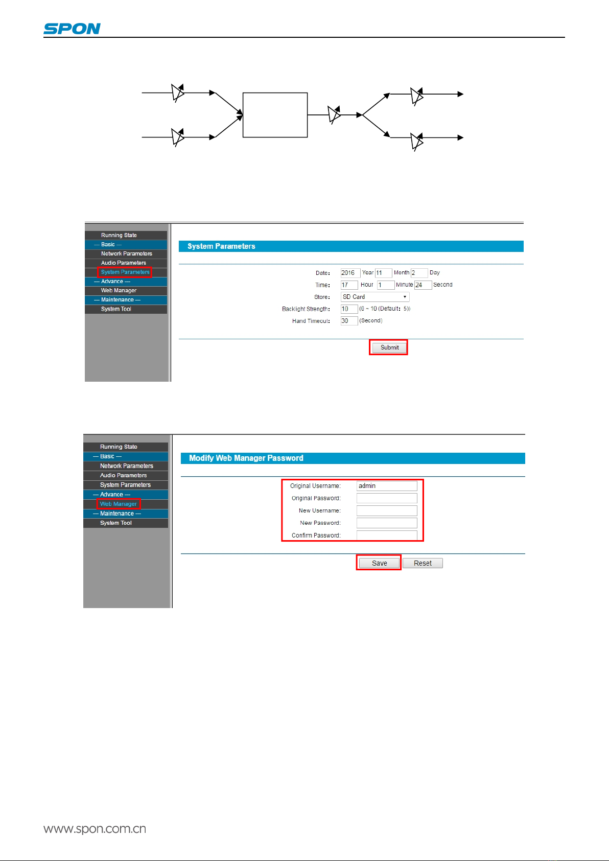
System parameters
In the offline state, the terminal can be set through a Web page to set terminal time parameters: basic setting-time setting, as the
following Picture:
Web management
You can modify the account number and password of the login Web page in the Web management parameters.
Restarting device
User can click “restart device” to restart the device.

IP Amplifier User Manual
9
Resetting to defaults
Resetting defaults: all the parameters will reset to defaults.
Downloading word stock
In the web browser to visit IP network terminal WEB page, click “device maintenance”->“system tool”->“download word stock”,
choose the manufacturer offer required download files, click “download character library” button to start download.
Note: please don`t download word stock except the character showed need to modify
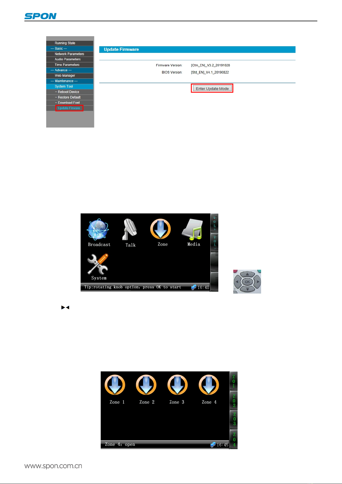
Upgrade firmware
In the web browser to visit IP network terminal WEB page, click “device maintenance”->“system tool”->“upgrade firmware”,click”
enter upgrade firmware mode” button, enter the upgrade firmware Web page, then choose the manufacturer offer required
upgrade firmware files, click “upgrade firmware” button to start upgrade.
IP Amplifier User Manual
10
Note: please don`t upgrade firmware except have special demands
Basic function
Starting up interface
Operation terms description:
Confirm button: press down single button coding rotation knob;
Rotate function rotation knob:Rotate single button coding rotation knob;
Click any function button: press down function select button;
Press (confirm) into system fuction interface, enter into corresponding fuction according to icon information.
Or press “▲▼ ” to select coresponding fucntion and repress OK for executing, press setting button can check the system
information.
Output volume adjustment
Click【volume+】or【volume-】function button can adjust the total output volume, it can rotate the rotation knob to adjust output
volume under start interface. It can adjust according to the prompt information under other function interface.
Zone control
IP amplifier can control 4 zones, the zone function will closed at default state, press down the right zone button to open the

IP Amplifier User Manual
11
zone(press down double will closed),click【confirm】button will exit the zone control interface.
It can press NO. 1、2、3、4 on remote control to change zone1-4 zone state, if the zone 1 is open, press NO.1 button will close
the zone 1, and press it again to open it.
Calling to terminal
When on-line state, make the rotation knob to ”intercom”, then click 【confirm 】button to initiate calling. The called target is
controlled by server software. It also can press call button on remote control to initiate intercom directly. It can operate when off
the line.
When at intercom state, the rotation knob can adjust the microphone voice.【Voice+】and【Voice-】can adjust the speaker voice.
Click【stop】will end the intercom.
Terminal broadcasting
When on-line state, make the rotation knob to “broadcast”,click【confirm】button to initiate all zones broadcast. It can make
broadcast when off line.
Default state, it can make the dynamic microphone insert to MIC1 broadcast, rotate MIC1 rotary knob to adjust volume. It also
can click【line】button switch to microphone broadcast, rotate function rotary knob to adjust microphone volume. Click【stop】
button to cancel the broadcasting.
Local broadcasting
Rotate function rotary knob to local play, click【confirm】button enter SD card local play. (Audio files must be stored in SD card
MUSIC folder)
In local broadcasting, rotate function rotary knob to choose the playing music, it support WAN and MP3 audio file, click【confirm】
button to broadcasting at playing state to click【confirm】button to stop and continue broadcasting, click【stop】button to stop
broadcasting, click【sound】button to switch different sound mode. Click【back】button to return the function interface.
1) When at free state, press [VOD] button on the remote control, LCD screen will display program menu.
2) [▲][▼] button moved cursor menu, press [OK]button, enter the next menu level or broadcasting the file directly.
3) After start broadcasting files, click[>|| ]button to pause, click [<<][>>]button to fast-forward and fast backward, click [■]button to
stop, click the first [A-B]button to fix the beginning point of the cycle ,click the second [A-B]button to end and loop playback, click
the third [A-B]button back to normal broadcasting.
4)Click [cancel] button return to the last menu level state.
IP Amplifier User Manual
12
5) If it needn`t the VOD function, please click [cancel] button to return to the free state.
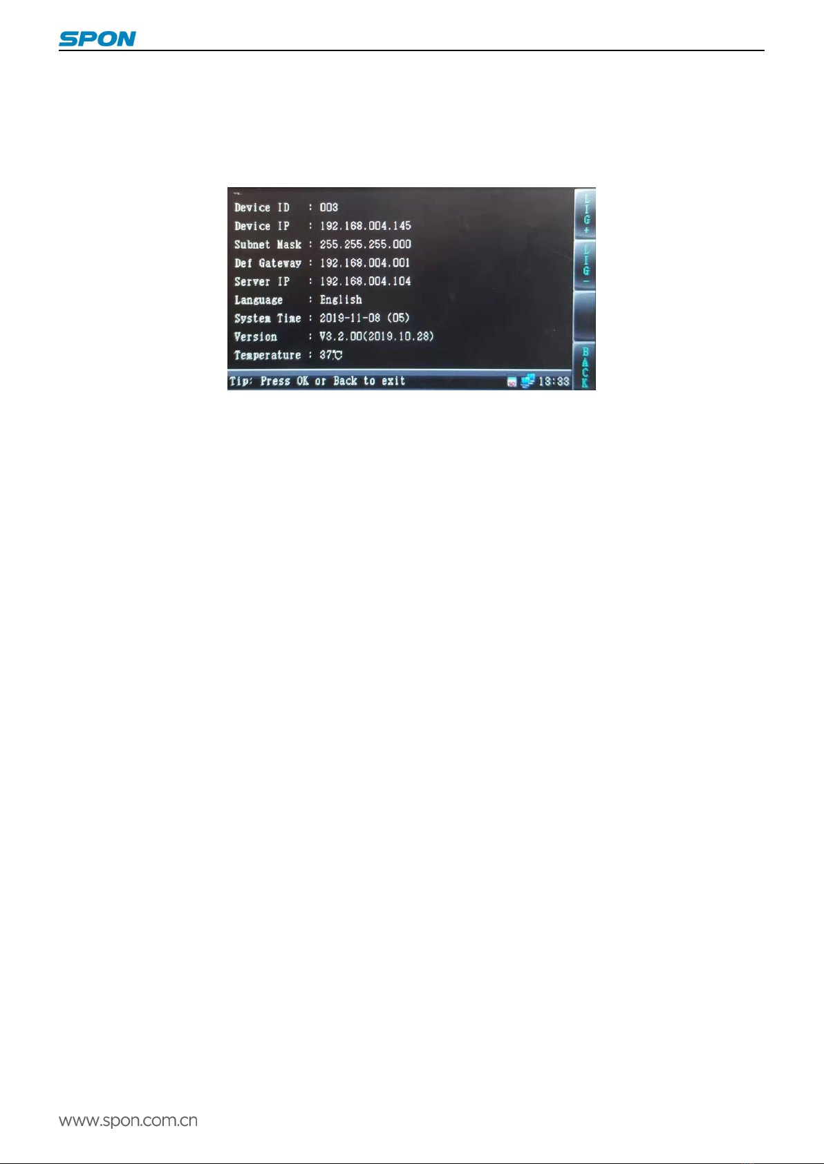
System information
Enter the system information it can check the terminal configuration information, version, clock information and the computer
case temperature.. It can press the remote control setting button to check the system information directly.
Receive call
When the terminal haven`t broadcast and no network timing task, it will receive other terminal call demands, and enter the
intercom state. Click【stop 】button to exit the intercom. The intercom sound source only can from speaker output, and from
Microphone input.
Receive Broadcasting
At on-line state,when the terminal haven`t broadcast, it can receive other terminal`s broadcast or the server`s broadcast; When
receiving the broadcast, rotate function rotary knob or【Volume+】/【Volume-】to adjust the output volume. You can also use remote
control volume[+],[-] button to adjust. Notice: when receiving broadcast MIC3 port should not sound resource input. Broadcast
output only can from the amplifier or the active speaker
Network timing task
When receiving the time ring from the server, the terminal skip to the network timing task interface. Rotate function rotary knob or
【Volume+】/【Volume-】to adjust the output volume.
Local timing broadcast
Local set-time broadcast is to play the timing ring task of SD card or built in Nandflash clip timing ringing the bell, timing ring task
is lead out from server, and stored at SD card. Lead out the local set-time task please refer to the chapter8.15 introduction.
The local timing task import
(1)Download from the server directly
Operation steps:
1)Insert the SD card to reader;
2)Insert the card reader into the computer USB port.
3)From the server【file】menu to choose【lead out…】menu item, it will pop-up the timed task dialog.

IP Amplifier User Manual
13
4)The assigned lead out solution and timed task;
5)The assigned SD card reader driver is the lead out driver;
6)Click【confirm】button to lead out the timed task, this timed task information and MP3 file will write in the SD card automatically;
7)Insert the SD card into the SD card slot back, restart the terminal;
8)After the terminal identified the timed task information of SD card, it will show the below icon on the screen, the terminal will
execute the timed task automatically.
(2)Remote update the SD card
The premise of remote update SD card is that SD card is already inserted to the terminal slot and identified.
Install “Updated SD card tool at remote” at first.
According to “download from server directly” way to lead out the timed task to local U disk, then follow “Update SD card at remote
tool” suggestive steps to lead out the task of U disk to updated SD card.

IP Amplifier User Manual
14
Alarm input triggers SD card to broadcast audio
When the alarm input 1 is short circuit connected, the IP amplifier plays the "1.mp3" audio file in the "short circuit input.001"
file in the MUSIC folder, and stop playing when disconnected.
Similarly, the alarm input 2 is short circuit connected to play the "2.mp3" audio file in "short circuited input.002", and the
alarm input 3 is short circuit connected to play the "3.mp3" audio file in "short circuited input.003".
The audio files placed in "short circuiting input.001" must be named "1.mp3", the audio files placed in "short circuiting
input.002" must be named "2.mp3", and so on.
The mentioned three audio files must be MP3 files in 128K format and the name can not be changed, only the content of the
audio files can be replaced.
The folders of "short circuit input.001" and "short circuit input.002" can be initialized and created by remote SD card tools,
while the folder of "short circuit input.003" needs to be created manually.
Fault exclude
Why the terminal is still "offline"?
1).Check the software server and the main controller is normal opened or not. It`s required to close all firewall before open
the software server (including system built-in firewall and other antivirus software firewall).
2).Check the network connection is normal or not. After the terminal powered on, the network port green light is norm on,
meantime the orange light will be short and fast flash, it means the network cable hard-connected normal. If the network port
green light is not on, it means the network hard-connected problem, please check the terminal network cable and switcher
whether they work normal, damaged and disconnect or not etc.
3).Check the terminal IP setting. Please check the terminal ID, sever IP, local IP, gateway IP ...etc parameters.
Why it appears "terminal network services (UDP) start fail" warning within the process of start server software?
Appearing this warning information, it’s usually the local network connection has been disconnected, please connect the
local network cable well and exit the software, then restart it.
When web show abnormal?
Please clear the caches or change the browser.
How to change the web login account and password?
1 .Click the password setting in webpage .
2. Input the old account and old pass word.
3. Input the new account and new pass word.
4. Input the new password again for confirmation
5. Click save .
The new account and new password will be effective after reboot.

IP Amplifier User Manual
15
Copyright statement
Copyright
The copyright is reserved of the SPON Communication Technology Co., LTD (abbreviation SPON), if without the permission
of the company in written form, any company and personage shall not arbitrarily excerpt, copy mentioned file information,
and shall not spread in any forms.
According to the legal provisions, copy including translate to other language or switch to other format. Mentioned document
spreading in network media, SPON allow download and print for personal uses. Any parts of the document can not be
modified and for commercial uses. If any damage and losses which is caused by illegality modify and switch the document,
SOPN shall not take any responsibility.
Guarantee
Regarding to the information of the mentioned handbook, if any modify, kindly understand that there is no any notice.
The handbook shall provide the correct indication, information and suggestion, and not guarantee to any indicated and
implied information. User should take the responsibility of the products applying.
SOPN shall not making any guarantee for the handbook, including but not only for the guarantee of implied marketability and
specific purpose. Also SPON shall not take any responsibility, if any indirect or incidental losses caused by mistaken use of
the handbook.
Table of contents


