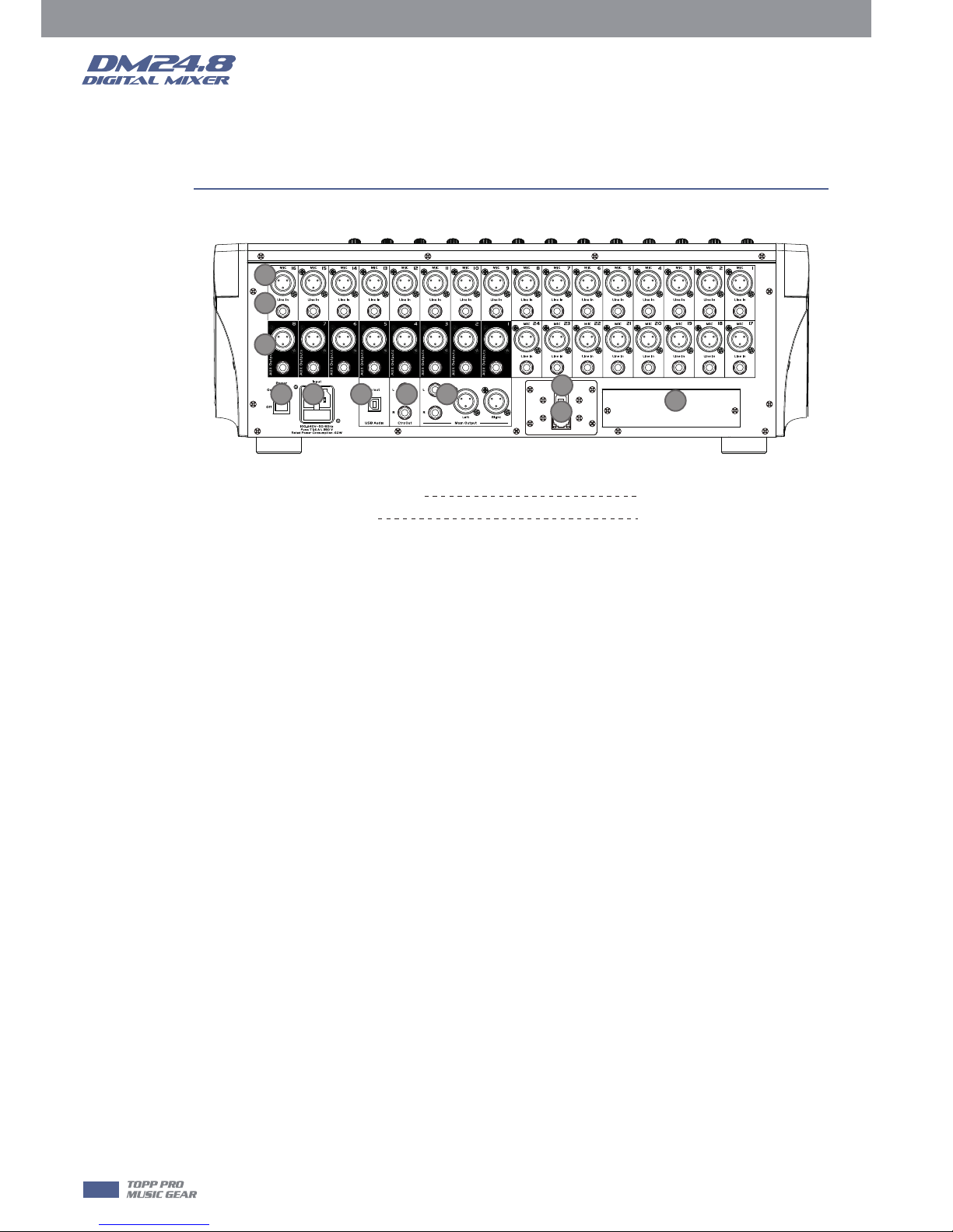
Topp Music Gear DM24.8 User manual

24 mic preamplifiers with dedicated trim control
DM24.8

2

Index
front Panel
3
Page7: 1. Ch1-24 input gain control knob
Page8: 7. Automix
Page9: 10. Gate
Page10: 14. FX Edit
Page11: 18. Save/Load
Page12: 23. Solo
Page13: 31. DCA Clear
Page14: 36. DCA Groups1-12
Page15: 45. LCD
6. Digital In/Out
17. System
30. Name
35. Talkback
44. HP1
22. Adjust Parameter Knob
13. Channel
9. Assign
1 2 40
3
4
5
6
7
8
9
10
11
12
13
14 16
21
22
21
17 41
18
15
19 20
21
43
42
2327
28
29
31
32
33
37
38
39
34
45
35
44
36
30
24
25
26
25
21
16

Rear Panel
Index
Page15: 1. MIC Input Jack
Page16: 8. Ctrl Out
7. Main Output
11. Power Switch
4
1
2
3
4
91011 5
6
78
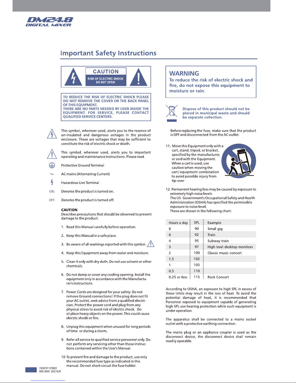
under the EM disturbance, the ratio of signal-noise may be changed above 3dB.
* The mixer for professional use. They can be used in following electromagnetic environment:
residential, commercial and light industrial, urban outdoors.
They are the apparatus not intended for rack mounting.
* The peak inrush currents equal to 8.33 A.
*This device complies with part 15 of the FCC Rules. Operation is subject to the following two
conditions: (1)this device may not cause harmful interference, and (2)this device must accept any
interference received, including interference that may cause undesired operation. Changes or
modifications not expressly approved by the party responsible for compliance could void the
user's authority to operate the equipment.
NOTE: This equipment has been tested and found to comply with the limits for a Class B digital
device, pursuant to Part 15 of the FCC Rules. These limits are designed to provide reasonable
protection against harmful interference in a residential installation. This equipment generates,
uses and can radiate radio frequency energy and, if not installed and used in accordance with the
instructions, may cause harmful interference to radio communications. However, there is no
guarantee that interference will not occur in a particular installation. If this equipment does cause
harmful interference to radio or television reception, which can be determined by turning the
equipment off and on, the user is encouraged to try to correct the interference by one or more of
the following measures:
-- Reorient or relocate the receiving antenna.
-- Increase the separation between the equipment and receiver.
-- Connect the equipment into an outlet on a circuit different from that to which the receiver is
connected.
-- Consult the dealer or an experienced radio/TV technician for help.

Table of contents
1. Introduction
2. Summary of Features
3. Usefull Data
4. Control
5. Software Update
6. Hookup Diagram
7. Block Diagram
8. Technical Specification
9. DSP Control
9.1 Mixer interface
9.2 Long Faders interface
9.3 Assign interface
9.4 Channel interface
9.5 Gate interface
9.6 COMP interface
9.7 PEQ interface
9.8 GEQ interface
9.9 FX1-2 interface
9.10 Digital In interface
9.11 Digital Out interface
9.12 DCA Set interface
9.13 Meters interface
9.14 Routing interface
9.15 System interface
9.16 Load/Save interface
9.17 Copy interface
9.18 Automix interface
9.19 RTA interface
9.20 48V interface
10. Guarantee
11. Notes
6
6
6
7
16
17
18
19
21
21
22
23
24
26
27
28
29
30
32
33
33
34
35
36
37
37
38
39
39
40
41
5

6
Introduction
Thank you for purchasing our Digital Mixer. With 24 line-level inputs, 24 microphone preamplifiers; Digital
4 band full parametric EQ; Compressor; Gate; Delay; Remote control; 13 precision motor fader for lever
control; Large and small LCD display operation in real-time; Program, save, load, and copy functions and
so on. This Digital Mixer helps you creating a wonderful show. It is easy to operate though it has powerful
function.
We suggest that you use this manual to familiarize yourself with the features and applications before
using.
Summary of Features
Usefull Data
Please write your serial number here for future reference.
2
1
3
Standard Features
- 24 microphone preamplifiers and line-level inputs
- +48V phantom power
- 8 Aux sends (contain 8 TRS ‘1/4’ interface and 8 'XLR’ interface)
- 1 Main L/R Output(contain 1 TRS ‘1/4’ interface and 1 'XLR’ interface)
- All channels Control Room outputs
- 1 headphones output
- USB Stereo recording/playback
- USB or network port firmware update interface, can be used to connect ipad remote control APP
- 2 internal FX
- 13 100mm precision motor fader
- 7 inch color LCD touch screen for graphical view and setup
- Two-color LCD displaying channel information
- 24-bit/48KHz sampling rate
- Program, save, load & copy functions
- Digital noise gate
- Digital compressor/limiter
- Digital 4-band full parametric EQ
- PAN, Phase reverse, Time delay
- DCA for Digital Control Audio or MUTE
- Lock and unlock function
- Change the password
- Automix, RTA, Talkback
Optional Features
- T-32DANTE network audio interface, field installable
- T-32USB multi-track audio interface, field installable

7
Control
Function Buttons and Knobs
1. Ch1-24 input gain control knob
The knob Ch1-24 control the gain level of the channel's input.
Note: It is very important to properly set the level of the input gain to minimize noise and avoid overload
distortion.
When the signal> + 18dB, this Clip LED lights green, indicating the relevant channel signal overload.
When the signal> -30dB, this Sig LED lights green, indicating the status of the relevant channel input signal.
2. Control Room Knob
This knob controls the overall output level for control room.
3. Phones Knob
This knob controls the overall output level for headphones.
4. Route to Main
Press the input channel button, then press this button, can quickly route the input channel to main
(including CH1-24, AUX1-8 and FX1-2).
5. DC48V Phantom Power button
Every microphone input equips with an individual phantom power which is controlled by the 48V phantom
power button. It will illuminate when phantom power is activated.
Note: Please notice that only the condenser microphone needs phantom power.
Please do not supply phantom power to any device which don’t need phantom power otherwise the device
may be damaged.
6. Digital In/Out
Press this button, it will switch between Digital In and Digital Out function.
This button engages and disengages the digital channel when you have an optional input/output module
inserted.
• Digital In
The button will illuminate to indicate that current channel has been selected as digital input. The window is
as below.
For the detail operation, please refer to introduction of DSP Control section.
4
1 2
3
4
5
6
- DC48V -

8
Control
• Digital Out
The button will illuminate to indicate that current channel has been selected as digital output. The window
is as below.
For the detail operation, please refer to introduction of DSP Control section.
When the button illuminated, please pay attention to which channel is Digital Input and which channel is
Digital Output during operation.
7. Automix
Press this button to activate the Automix function. The Automix automatically
reduces the level of a microphone when it is not being used. Consequently it
lowers the rumble, reverberation and other extraneous noise that occur when
several microphones operate simultaneously.
8. Pan Knob
The encoder controls signal level from left to right for the selected input channel.
The LCD display shows the setting in real time. If two channels have been linked
as stereo pair, the LCD display will automatically change to stereo pan.
9. Assign
Press this button to enter assign page, signal from a selected input channel can
be assigned to Main, AUX1-8, and FX1-2. The window is as below.
For the detail operation, please refer to introduction of DSP Control section.
4
7
8
9
- Digital In - - Digital Out -
- Automix - - Assign -

Control
9
10. Gate
Noise gate attenuates signals that below the threshold and allows signals to pass through only when they
are above a threshold setting. The window is as below.
For the detail operation, please refer to introduction of DSP Control section.
11. Comp
A compressor reduces the level of an audio signal if its amplitude exceeds a certain threshold. The window
is as below.
For the detail operation, please refer to introduction of DSP Control section.
12. PEQ
An equalizer is a filter that allows you to adjust the level of frequency in the range of
20Hz-20KHz. The window is as below.
For the detail operation, please refer to introduction of DSP Control section.
13. Channel
Press this button, you will see Channel page on LCD screen. It gives you a preview of
other function such as Polarity, Delay, Link, Gate, EQ, Compressor etc. You can also
adjust corresponding parameters that show on the screen. But for Gate here, you can
only adjust threshold; For Compressor, you can only adjust threshold; For EQ, you can
adjust nothing here.
For the detail operation, please refer to introduction of DSP Control section.
4
10
11
12
13
- Gate -
- PEQ - - Channel -
- Comp -

10
Control
14. FX Edit
Press this button can show and editor the setting of internal effects. Each of the FX owns 12 program
effects. The window is as below.
For the detail operation, please refer to introduction of DSP Control section.
15. Copy
Press this button and select a channel to copy the setting parameters of this channel to other channels.
For the detail operation, please refer to introduction of DSP Control section.
16. Routing & Sends on Faders AUX1-8/FX1-2
Press this button, users can select one or several channels to assign the signal to corresponding outputs.
Routing: Press this button to enter the assign page, select the channel to be assigned (AUX1-8, FX1-2 and
Main) and click Enter to confirm.
Sends on Faders AUX1-8/FX1-2: The function is the same as the Routing button. Press this button and it will
flash, then select the channel to be assigned.
For the detail operation, please refer to introduction of DSP Control
section.
17. System
Press this button to go to System page, as well as show and edit
parameters of the system, as below picture show.
For the detail operation, please refer to introduction of DSP Control
section.
4
- Routing & Sends on Faders AUX1-8/FX1-2 -
- FX Edit -
- System -
- Copy -
14 16 17
15
16

4
Control
11
18. Save/Load
Save: Used to save the current settings (Scene, DSP, GEQ, FX).
Load: used to load presets (Scene, DSP, GEQ, FX).
By pressing this button to achieve the switching of save and load.
19. Mixer
Press this button, you will see mixer page on LCD screen, where you can control all the input and output
channels’ level, solo and mute, as well as DCA group level control, the window is as below.
For the detail operation, please refer to the introduction of DSP Control section.
20. Enter(TAP)
This button can activate two types of function.
• Enter: Confirm the edited parameter values.
When there is a confirmation message jump out on the screen, press Enter button to answer “yes”.
• TAP: In the FX1 and FX2 page, it will switch to TAP function, you can use this button to enter a delay time
in tempo with the music being played.
As the function of this button will be a little bit different in different function, please notice the notes that
are shown on the screen when operating.
21. UP & Down & Left & Right button
These buttons move the cursor around the display page, or select and delete parameters and options.
Sometimes, Up button function is the same as Left button, while Down button function is the same as Right
button. But in GEQ, Up and Down adjust gain level, while Left and Right adjust frequency.
As the function of this button will be a little bit different in different function, please notice the notes that
are shown on the screen when operating.
22. Adjust Parameter Knob
This Encoder adjusts the parameter values of selected control that are shown on the LCD display. Turning it
clockwise increases the value and counterclockwise decreases the value.
As the function of this button will be a little bit different in different function, please notice the notes that
are shown on the screen when operating.
21
22
21
18
19 20
2121
- Mixer -
- Save - - Load -

4
12
Control
23
24
25
25
25
23. Solo
Press this button will send its channels or buses to the control room outputs. It will illuminate as
has been pressed and enabled.
24. Mute
Press this button will mute selected channel and all of its assigned outputs. It will illuminate
when the button has been pressed and enabled.
25. Select Button
There are 12 select buttons as you can see on the panel. Press this button will route its channel
to add DSP setting and assign its output. It will illuminate as has been pressed and enabled.
Press ”1-12” button, which means CH1-12 correspondingly, press “13-24” button, which means
CH13-24 correspondingly, and press ”Levels” button, which means AUX1-8 and FX1-2
correspondingly. In DCA window, you can select group channels by this button.
26. Volume Fader
There are 13 faders on the panel which is used for level adjustment of the corresponding
channel, including 12 faders for CH1-24 and 1 for Main.
27. S Clear
Press this button to clear the solo function for all of the soloed buses or channels.
28. M Clear
Press this button to clear the mute function for all of the muted buses or channels.
29. Stereo Link
Press this button to select the Pan function, then rotate Parameter Adjust encode to control
signal level from left to right for the selected input or output bus. If you have adjusted a channel
pan, please just touch 2 times on the screen and make it back to the centre position. The LCD
display shows the setting in real time. If two channels have been linked as stereo pair, the LCD
display will automatically change to stereo pan.
22. Link button Input channels, aux buses, can be linked as a stereo pair. It will illuminate if the
stereo link button has been pressed and enabled. The stereo pairs are predefined and cannot be
changed. They are as follows:
Channels 1 - 2 / Channels 3 - 4 / Channels 5 - 6 / Channels 7 - 8 / Channels 9 - 10
Channels 11 - 12 / Channels 13 – 14 / Channels 15 - 16 / Channels 17 - 18 / Channels 19 - 20
Channels 21 - 22 / Channels 23 - 24 / Aux 1 - 2 / Aux 3 - 4 / Aux5 - 6 / Aux7 - 8
A stereo link can be enabled when either channel in the pair is selected by pressing the Link button. When
the Link button is illuminated which indicates the Stereo Link function enabled, all DSP setting, solo status
and main assignments are passed to the other channel in the pair.
• Link & DCA: After link, the channels can also be grouped to DCA as stereo channel, but not able to cancel
the link in DCA. On the contrary, if the channel has been grouped to DCA, it can not link at all, but its paired
channel can link.
For example, channel 5 is linked with channel 6, then both channel 5 and 6 can be grouped to DCA. But if
channel 5 has been grouped to DCA first, it can not link to channel 6, but channel 6 can link to channel 5.
• Link & Routing: The two linked channels can route as stereo channel, while routed channels can also link
later. Please note that this is a nondestructive passing, the other channel's previous setting will be restored
after the Link button is disengaged. For example, when Channel 6 has been selected, then press Stereo Link
button, all of Channel 6's setting will be copied onto Channel 5. The Channel 5's own setting will restore after
the Link button has been disengaged.
30. Name
Press this button to rename the channel.
Operation: Press Name button--- Select the channel which need to be named--- Edit the name--- Enter.
26
27
28
29
30

4
Control
13
31. DCA Clear
Press this button to clear the corresponding DCA group.
Operation: Press DCA Set button--- Select the DCA group which need to be cleared--- Press DCA
Clear button--- Yes.
32. FX Mute
This button is for FX function, when press it, effects of FX1-2 will be mute synchronously, which
is similar to MUTE button.
33. DCA set
Digital Control Audio (DCA) can realize group assignment. DCA volume control will always
leave the same ratio between the channel fader levels, independent of the volume control.
Press this button, it will flash until some channels have been selected, then press it again to
save the settings and turn off the button. For example, if you want to set CH1 & CH2 as DCA1,
the steps are: Press DCA Set to enable DCA setting --- Press DCA1, then select CH1 & CH2 ---
Press DCA Set again to confirm.
The corresponding window is as below picture show.
For the detail operation, please refer to introduction of DSP Control section.
34. Meters
Press this button to enter meters check page, as below picture show, for the details, please
refer to corresponding introduction of DSP Control section.
35. Talkback
Insert the microphone on the rear panel CH24 Mic input jack. Press this button enter the Talkback interface
and the button will be illuminated at the same time. Touch the Talkback Active box on the screen to enable
the Talkback function. CH24 can be assigned to Main and AUX1-8. There are two modes:
PTT mode: Select PTT mode, you must always press the Talkback button to speak, and release to end the
speaking.
ON/OFF mode: Select ON/OFF mode, press the Talkback button to speak.
31
32
33
34
35
36
- DCA set -
- Talkback -
- Meters -

4
14
Control
36. DCA Groups1-12
Press this button to activate the DCA level adjustment function. Slide the corresponding fader to
adjust the level of the pre-defined DCA group. If it has not been DCA grouped, the screen will
prompt "This DCA group is not defined".
37. RTA
RTA: Real-Time Analysis. Press this button to activate the RTA function. With 31 frequency points
analysis, each frequency corresponds to a level value, the level of each frequency can be seen on
the screen in real time.
38. GEQ
Press this button to activate GEQ function (note: only for output channel). In GEQ page you can
set the 31-band EQ. The window is as below.
For the detail operation, please refer to introduction of DSP Control section.
39. Select Main
It is used for selecting Main channel. Enter main channel interface by pressing this button.
40. USB Lamp Connector
This connector can connect with a 5V-500mA lamp which can help you use the digital
mixer whether in dark situation or not conveniently.
41. LED Level Indicator
It indicates the level of the MAIN channel or SOLO channel. By default, it is used to
indicate the MAIN channel level when the SOLO METER button is not pressed.
42. Solo Meters
When the button is off, meters above it indicate input level of main, while illuminated
indicate input level of Solo.
43. PFL
The default setting for the Solo bus is After-Fader Listen (AFL); by pressing PFL,
Pre-Fader Listen is enabled. In either mode, press Solo on any channel or bus to route that
channel to the Solo bus and has no effect on the main.
44. HP1
This jack is used for connecting headphones.
- RTA - - GEQ -
37
38
39
36
40
41
43
42
44

4
Control
15
45. LCD
The digital mixer equips an 800*480 large LCD screen (for
displaying the current operation interface) and 13 128*64 LCD
screens (for displaying channels, channel names, and level values).
Rear Panel
1. MIC Input Jack
This Digital Mixer equips 24 microphone preamplifiers for use with all types of microphones. The
preamplifier has a Class A input buffer which followed by a dual-servo gain stage. This arrangement will
bring ultra-low noise and wide gain control which help to boost signals without increasing unwanted
background noise.
2. Line Input Connector
This Digital Mixer is equipped with 1/4 "balanced TRS connectors for line input.
Note: Please notice that there will be a momentary spike in the output when plugging in a microphone or a
line-level input device, or turning phantom power on or off. So it should be better to mute or turn down the
channel fader before changing connections or turning phantom power on or off.
3. Aux Outputs
These are balanced mono outputs for each auxiliary. The Aux mixing will be output from these 8 Aux
channels. Aux mixing can be used for monitoring and effects processing.
4. Optional module
Select our optional module that you want for extra function.
Please contact with distributor to get more information about the optional modules.
5. USB
This port is for remote control or firmware update.
6. Ethernet
This port is for Ethernet control or firmware update.
7. Main Output
This Digital Mixer features both XLR and TRS main outputs.
45
1
2
3
4
91011 5
6
78

4
5
16
Control
8. Ctrl Out
These are the balanced control-room outputs. The level is controlled by the knob in the Control Room on the
top panel.
9. USB Audio In/Out
This port is for USB audio input and output. You can connect it to WINDOWS/MAC system without any USB
driver.
10. Power Input
The provided power cable can be plugged in.
11. Power Switch
Push the top part of the switch to turn on and the bottom part to turn off.
Software Update
We will always update the Digital Mixer software, please download the latest version from below sites:
www.seikaku.hk .
Since function of the Digital Mixer will also change when you update the software, this manual can help you
familiar with the basic function, for the precision, please refer to the real digital mixer.
Note: When you update the firmware, all the parameters you had saved in the mixer may be destroyed.

6
Hookup Diagram
17

7
18
Block Diagram

8
Technical Specification
19
Microphone input Electronically balanced
Frequency Response to Main Output 22Hz~202Hz at 0dBu ±1.5dBu
Distortion(THD&N) to Main Output <0.01% at 0dBu 1KHz
Gain 0dBu~50dBu
SNR(Signal to Noise Ratio) 111dB
Maximum Input Level +20dBu ±0.5dBu
Phantom Power(+/-3V) +48VDC
Line input Electronically balanced
Frequency Response to Main Output 22Hz~22KHz at 0dBu ±1.5dBu
Distortion(THD&N) to Main Output <0.01% at 0dBu 1KHz
Gain -20dBu~+30dBu
Maximum Input Level(Gain at 0dBu) +20dBu ±0.5dBu
USB stereo inputs
Frequency Response to Main Output 22Hz~22KHz at 0dBu±1.5dBu
Distortion(THD&N) to Main Output <0.01% at 0dBu 1KHz
Maximum Input Level 10dBu ±0.5dBu
Main Outputs
Maximum Outputs Level +20dBu ±0.5dBu
AUX SEND (XLR)
Maximum Output Level +20dBu ±0.5dBu
AUX SEND (1/4 TRS)
Maximum Output Level +20dBu ±0.5dBu
Control Room Outputs
Maximum Output Level +20dBu ±0.5dBu
HeadPhones Level
Maximum Output Level +15dBu ±0.5dBu
System Crosstalk
Input to Output(at + 0dBu 1KHz) -88dBu
Adjacent Channels(at + 0dBu 1KHz) -87dBu
Noise(Bus noise) -91dBu

8
20
Technical Specification
Noise Gate
Threshold Range -84dBu ~ +20dB
Attack time 0.5mS ~ 200mS
Relesae time 10mS~1S
Compressor
Threshold Range -30dBu -+20dB
Attack time 10mS ~ 150mS
Relesae time 10mS~1S
Ratio 1:1 to Limit
Gain 0dBu - +24dB
EQ
Low (LowPass or LowShelf) 21Hz~19.2KHz +/- 24dB
Low Mid 21Hz~19.2KHz +/- 24dB
High Mid 21Hz~19.2KHz +/- 24dB
High(HighPass or HighShelf) 21Hz~19.2KHz +/- 24dB
Digital Audio
ADC Dynamic Range 114dB
DAC Dynamic Range 114dB
Internal Processor 32-bit , floating point
ADC,DAC bit depth 24bit
Impedances
Microphone input 6.8KΩ
Line input 75K
Stereo input 27K
All other output 240Ω
operating free-air temperature range 0~40℃
storage temperature range -20℃~45℃
Table of contents
Other Topp Music Gear Amplifier manuals

Topp Music Gear
Topp Music Gear KS-CS 8A User manual

Topp Music Gear
Topp Music Gear KPA 300R User manual

Topp Music Gear
Topp Music Gear TRX2500 User manual

Topp Music Gear
Topp Music Gear THA-4 User manual

Topp Music Gear
Topp Music Gear TPS 16P User manual

Topp Music Gear
Topp Music Gear TMA250-4 User manual

Topp Music Gear
Topp Music Gear THA Series User manual

Topp Music Gear
Topp Music Gear TD-500.4 DSP User manual