Sportneer DY110 User manual
EN
Hereby,[ThousandshoresDeutschlandGmbH]declaresthattheradioequipmenttype[Exercise Bike
DY110] is in compliance with Directive 2014/53/EU.
The full text of the EU declaration conformity is available at the following internet address:
http://files.sportneer.com/s28-2399a-01-doc-en.pdf
EXERCISE BIKE
Model: DY110
User Manual
Thank you for choosing the Sportneer.
Please read this user manual carefully before assembly and use and keep it on hand for future reference.

21
Introduction
Congratulations on your purchase of Sportneer Fitness equipment. We hope you appreciate the style, quality, and
value that exercisers around the world have come to expect from Sportneer Fitness.
If you have any questions, concerns or product issues, please contact our customer service team and send an
email to support@sportneer.com.
Carefully read through the instructions contained in this manual. They provide you with important information
about assembly, safety, tness and use of the machine. Please read ALL the safety information contained on the
following page.
Safety Precautions
This exercise equipment has been designed and constructed to provide maximum safety. Nevertheless, certain
safety precautions should be taken when you use this exercise bike. Please observe the following safety
precautions:
1. Keep children and pets away from this equipment at all times. DO NOT leave them unsupervised in the room
where the machine is kept.
WARNING!
WARNING!
WARNING!
WARNING!
Product specication
Serial Number
WARNING!
Care should be taken in mounting or dismounting the exercise bicycle:
1. Regularly examine the exercise bicycle.
2. Worn or damaged components shall be replaced immediately or stop using the exercise bicycle until repair is
completed.
3. Only manufacturer-supplied components shall be used to maintain/repair the equipment.
4. If any of the adjustment devices are left projecting, user's movement will be interfered.
5. The exercise bicycle is only for consumer use.
WARNING: The heart rate monitoring system may be inaccurate.Excessive exercise may cause serious physical
damage or sudden death.If you feel dizzy or hard breath, stop exercising immediately.
CAUTION: Consult your doctor before beginning to use this equipment or any exercise program. Read all of the
instructions before using any exercise equipment.
DO NOT dispose of this product as refuse. This product is to be recycled. For proper disposal of this
product, please follow the prescribed methods at an approved waste center.
2. If you experience dizziness, nausea, chest pains or any other symptoms while using this machine, stop
exercising and seek immediate medical attention!
3. Use the machine on a level and solid surface and adjust the feet for great stability.
4. Keep your hands away from any of the joints and moving parts.
5. Wear the suitable clothes, wear athletic shoes and and tie the laces securely during cycling. DO NOT wear
baggy clothing that might get caught in the machine.
6. This exercise bike must only be used for the purposes described in this user manual. DO NOT use accessories
that are not recommended by Sportneer Fitness. Read the user manual prior to use and follow all warnings and
instructions.
7. DO NOT place sharp objects near this exercise bike.
8. Any person with physical or coordination limitations should not use this exercise bike without the assistance of
a qualified person or doctor. Misuse of this machine may result in serious injury.
9. Do warm-up stretching exercises before using this exercise bike.
10. DO NOT use the exercise bike if it is not working correctly.
11. Before using this exercise bike, thoroughly inspect it for proper assembly.
12. Keep a perimeter of 24’’ (0.6 meter) around this exercise bike before operation.
13. This exercise bike can only be repaired by authorized and trained technicians.
14. Please follow the advice for correct training, as detailed in the Training Guidelines.
15. Only use the provided tools to assemble this exercise bike.
16. Replace the warning label if it’s damaged, illegible or removed.
17. This exercise bike have been designed for a maximum user weight of 240 lbs (110 kg).
18. This exercise bike can only be used by one person at a time.
19. DO NOT touch the high-speed flywheel to avoid serious personal injury.
20. When not using this exercise bike, rotate to the end in the resistance increase direction to lock the equipment.

43
Exercise Instructions
There are various benets to use this exercise bike: It can improve tness and muscle tone. When used in
conjunction with a calorie controlled diet, it can also help you lose weight.
1. Consult your doctor before starting any exercise program. It is advisable to undergo a complete physical
examination.
2. Cycle at the recommended exercise level. DO NOT over exert yourself.
3. If you feel any pain or discomfort, stop exercising immediately and consult your doctor.
4. Wear the appropriate clothes and footwear for the exercise; DO NOT wear loose clothes; DO NOT wear leather
soled shoes or footwear with high heels.
5. Do warm-up stretches before working out.
6. Get on this exercise bike slowly and securely.
7. Select the program or workout option that is most closely aligned with your workout interests.
8. Start slowly and work your way up to a comfortable pace.
9. Be sure to cool down after your workout.
Specications
Training Guidelines
Exercise is one of the most important factors in the overall health of an individual. Listed among its benets are:
• Improved capacity for physical work (strength endurance)
• Improved cardiovascular (heart and arteries/veins) and respiratory efciency
• Decreased risk of coronary heart disease
Maximum user weight
Machine weight 28.2kg / 62.2lbs
Size 111.2cm x 59.5cm x 136.1cm / 43.8” x 23.4” x 53.6”
Total surface area (footprint) of equipment 6616.4cm²
Power requirements 2 AAA Batteries
Operating voltage DC 3V
Frequency band 2.402GHz~2.480GHz
Maximum transmission power ≦4.54dbm
• Promoting body metabolism, e.g. losing weight
• Delaying the physiological effects of age
• Reduction in stress, increase in self-condence, etc.
There are several components of physical tness and each is dened below:
STRENGTH
The capacity of the muscle to exert a force against resistance: Strength contributes to power and speed.
MUSCULAR ENDURANCE
The capacity to exert a force repeatedly over a period of time, e.g. it is the muscular endurance of your legs to carry
you 10 km without stopping.
FLEXIBILITY
The range of motion of your joints: Improving flexibility involves the stretching of muscles and tendons to maintain
or increase suppleness, and it provides increased resistance to muscle injury or soreness.
CARDIO-RESPIRATORY ENDURANCE
The most essential component of physical tness, is the efcient functioning of the heart and lungs.
AEROBIC FITNESS
Aerobic tness is an exercise of relatively low intensity and long duration, which depends primarily on the aerobic
energy system. Aerobic means "with oxygen", and refers to the use of oxygen in the body's metabolic or energy-
generating process. Many types of exercise are aerobic, and by denition are performed at moderate levels of
intensity for extended periods of time.
ANAEROBIC TRAINING
Anaerobic training is an exercise which is intense enough to trigger anaerobic metabolism. This means “without
oxygen” and is the output of energy when the oxygen supply is insufcient to meet the body’s long-term energy
demands. (For example, a 100 meter sprint.)
OXYGEN UPTAKE
The effort that you can exert over a prolonged period of time is limited by your ability to deliver oxygen to the
working muscles. Regular vigorous exercise produces a training effect that can increase your aerobic capacity by
as much as 20% to 30%. An increased VO2 Max indicates an increased ability of the heart to pump blood, of the
lungs to ventilate oxygen, and of the muscles to take up oxygen.
THE TRAINING THRESHOLD
This is the minimum level of exercise which is required to produce signicant improvements in any physical tness
parameter.
110kg/240lbs

65
OVERLOAD
This is where you exercise above your comfort level. The intensity, duration and frequency of exercise should be
above the training threshold and should be gradually increased as the body adapts to the increasing demands.
As your tness level improves, the training threshold should rise. Working through your program and gradually
increasing the overload factor is important.
PROGRESSION
As you become more t, a higher intensity of exercise is required to create an overload and therefore provide
continued improvement.
SPECIFICS
Different forms of exercise produce different results. The type of exercise that is carried out is specic to the
muscle groups being used and to the energy source involved. There is little transfer of the effects of exercise, i.e.
from strength training to cardiovascular tness. That is why it is important to have an exercise program tailored to
your specic needs.
REVERSIBILITY
If you stop exercising or do not do your program often enough, you will lose the benets that you have gained.
Regular workouts are the key to success.
WARM-UP
Every exercise program should start with a warm-up where the body is prepared for the effort to come. It should
be gentle and preferably use the muscles group to be involved later. Stretching should be included in both your
warm-up and cool down, and should be performed after 3-5 minutes of low intensity aerobic activity or calisthenic
type exercise.
WARM DOWN OR COOL DOWN
This involves a gradual decrease in the intensity of the exercise session. Following exercise, a large supply of
blood remains in the working muscles. If it is not returned promptly to the central circulation, pooling of blood may
occur in the muscles.
HEART RATE
As you exercise, your heart beat increases. This is often used as a measure of the required intensity of an exercise.
You need to exercise hard enough to condition your circulatory system, and increase your pulse rate, but not
enough to strain your heart.
Your initial level of tness is important when developing an exercise program for you. When starting, you can get a
good training effect with a heart rate of 110-120 beats per minute (BPM). If you are more t, you will need a higher
threshold of stimulation.
To begin with, you should exercise at a level that elevates your heart rate to about 65% to 70% of your maximum. If
you nd this is too easy, you may want to increase it, but it is better to lean on the conservative side.
As a rule of thumb, the maximum heart rate is 220 minus your age. As you increase in age, your heart, like other
muscles, loses some of its efciency. Some of its natural loss is won back as tness improves. The following table
is a guide to those who are “starting tness.”
PULSE COUNT
The pulse count (on your wrist or carotid artery in the neck, taken with two index ngers) is done for ten seconds,
taken a few seconds after you stop exercising. This is for two reasons: (a) 10 seconds is long enough for accuracy,
(b) the pulse count is to approximate your BPM rate at the time you are exercising. Since heart rate slows as you
recover, a longer count isn’t as accurate.
The target is not a magic number, but a general guide. If you’re above average with your tness, you may work
comfortably a little above that suggested for your age group. The following table is a guide.
Don’t push yourself too hard to reach the gures on this table. It can be very uncomfortable if you over exercise.
Let it happen naturally as you work through your program. Remember, the target is a guide, not a rule, a little
above or below is just ne.
Two nal comments: (1) Don’t be concerned with day to day variations in your pulse rate because being under
pressure or not enough sleep can affect it; (2) Your pulse rate is a guide, so don’t become a slave to it.
MUSCLE SORENESS
For the rst week or so, muscle soreness may be the only indication you have that you are on an exercise program.
This, of course, does depend on your overall tness level. A conrmation that you are on the correct program is a
very slight soreness in most major muscle groups. This is quite normal and will disappear in a matter of days.
If you experience major discomfort, you may be on a program that is too advanced, or you have increased your
program too rapidly.
If you experience PAIN during or after exercise, your body is telling you something. Stop exercising and consult
your doctor.
WHAT TO WEAR
Wear clothing that will not restrict your movement in any way while exercising. Clothes should be light enough to
allow the body to cool. Excessive clothing that causes you to perspire more than you normally would gives you
no advantage. The extra weight you lose is body fluid and will be replaced with the next glass of water you drink.
Always wear a pair of athletic shoes.
Age target heart rate 25 30 35 40 45 50 55 60 65
10 second count 26 26 25 24 23 22 22 21 19
Beats per minute 156 156 150 144 138 132 132 126 120
Age target heart rate 25 30 35 40 45 50 55 60 65
10 second count 23 22 22 21 20 19 19 18 18
Beats per minute 138 132 132 126 120 114 114 108 108

87
BREATHING DURING EXERCISE
Do not hold your breath while exercising. Breathe normally as much as possible. Remember, breathing involves
the intake and distribution of oxygen, which feeds the working muscles.
REST PERIODS
Once you start your exercise program, you should continue through to the end. Do not break off halfway through
and then restart at the same place later on without going through the warm-up stage again. The rest period
required between exercises may vary from person to person.
Suggested Stretches
①HEAD ROLLS
Rotate your head to the right for one count while feeling the stretch up the left side of your neck. Next, rotate your
head back for one count, stretching your chin to the ceiling. Rotate your head to the left for one count, and nally,
drop your head to your chest for one count.
②SHOULDER LIFTS
Lift your left shoulder up toward your ear for one count. Then lift your right shoulder up for one count as you lower
your left shoulder.
③SIDE STRETCHES
Open your arms to the side and continue lifting them until they are over your head. Reach your left arm as far
upward as you can for one count. Feel the stretch up your left side. Repeat this action with your right arm.
④QUADRICEPS STRETCH
With one hand against a wall for balance, reach behind you and pull your left foot up. Bring your heel as close to
your buttocks as possible. Hold for 15 counts and repeat with right foot up.
⑤INNER THIGH STRETCH
Sit with the soles of your feet together with your knees pointing outward. Pull your feet as close into your groin as
possible. Gently push your knees towards the floor. Hold for 15 counts.
⑥TOE TOUCHES
Slowly bend forward from your waist, letting your back and shoulders relax as you stretch toward your toes. Reach
down as far as you can and hold for 15 counts.
⑦HAMSTRING STRETCHES
Sit with your right leg extended. Rest the soles of your left foot against your right inner thigh. Stretch toward your
toes as far as possible. Hold for 15 counts. Relax and then repeat with left leg extended.
⑧CALF/ACHILLES STRETCHES
Lean against a wall with your right leg in front of the left and your arms forward. Keep your left leg straight and the
right foot on the floor. Then bend the right leg and lean forward by moving your hip toward the wall. Hold, and then
repeat on the other side for 15 counts.
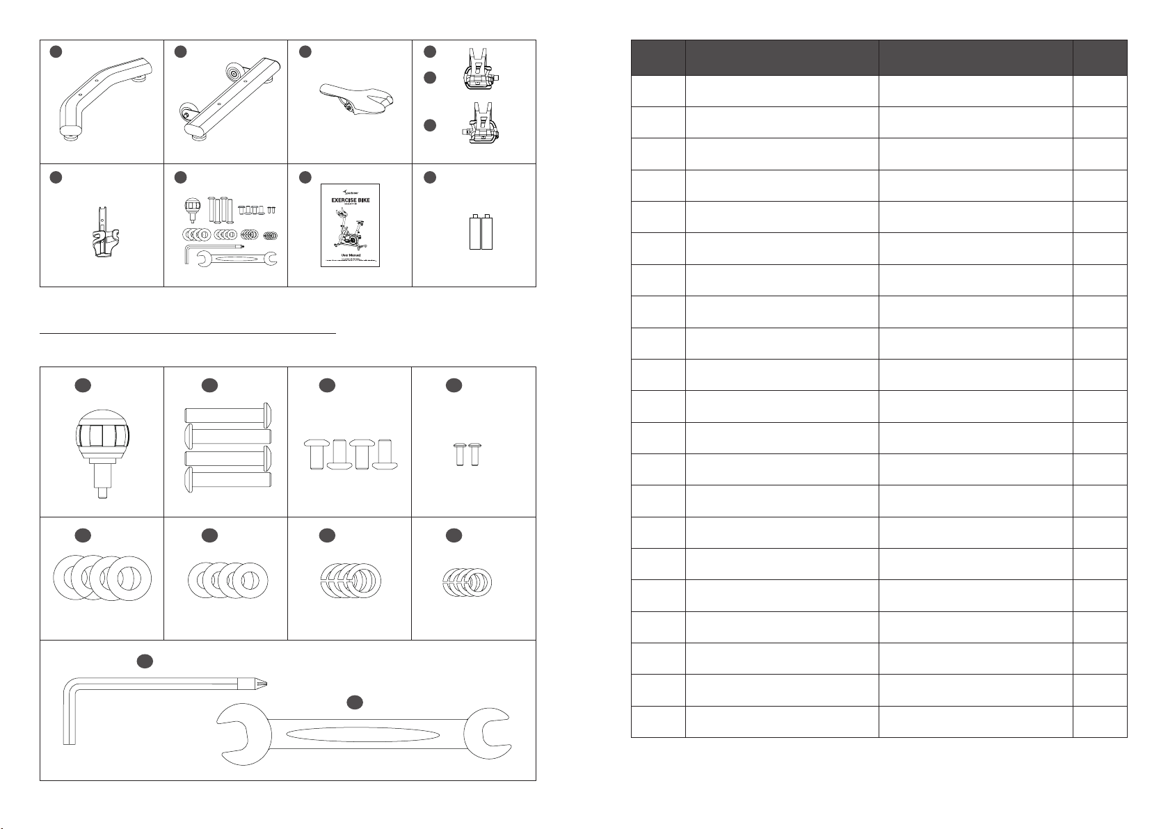
Schematic Diagram of Accessories
AB
C
109
GED
HI J J1
F
G1
G2
Schematic Diagram of Blister Board Set
A47 I1 I6
I2I3
I4
I5
I7
I8
Φ8.5xΦ16xT1.5
M8x15M10X55
4PCS E4 4PCS 4PCS
4PCS4PCS1PC
1PC
1PC
4PCS
2PCS
M4x8
Φ8Φ10Φ10.5xΦ20xT1.5
No. Part Name Specication Quantity
AMain frame set 1
B Support tube of handlebar 1
CHandlebar set 1
D Rear stabilizer set 1
E Front stabilizer set 1
F Seat 1
G Pedal set 1
HBottle holder 1
I Blister board set 1
J Instruction manual 1
J1 AAA Battery 2
A47 Quick release knob 1
I1 Flat inner hexagon screw M10x55 thread 15 4
I2 Spring washer Φ10 4
I3 Flat washer Φ10xΦ20xT1.5 4
I4 Flat hexagon screw M8x15 4
I5 Spring washer Φ8 4
E4 Flat washer Φ8.5xΦ16x1.5 4
I6 Philip flat screw M4x8 2
I7 Hexagon socket wrench L6+ cross head 1
I8 Outer hexagon wrench L13+L15 1
1211
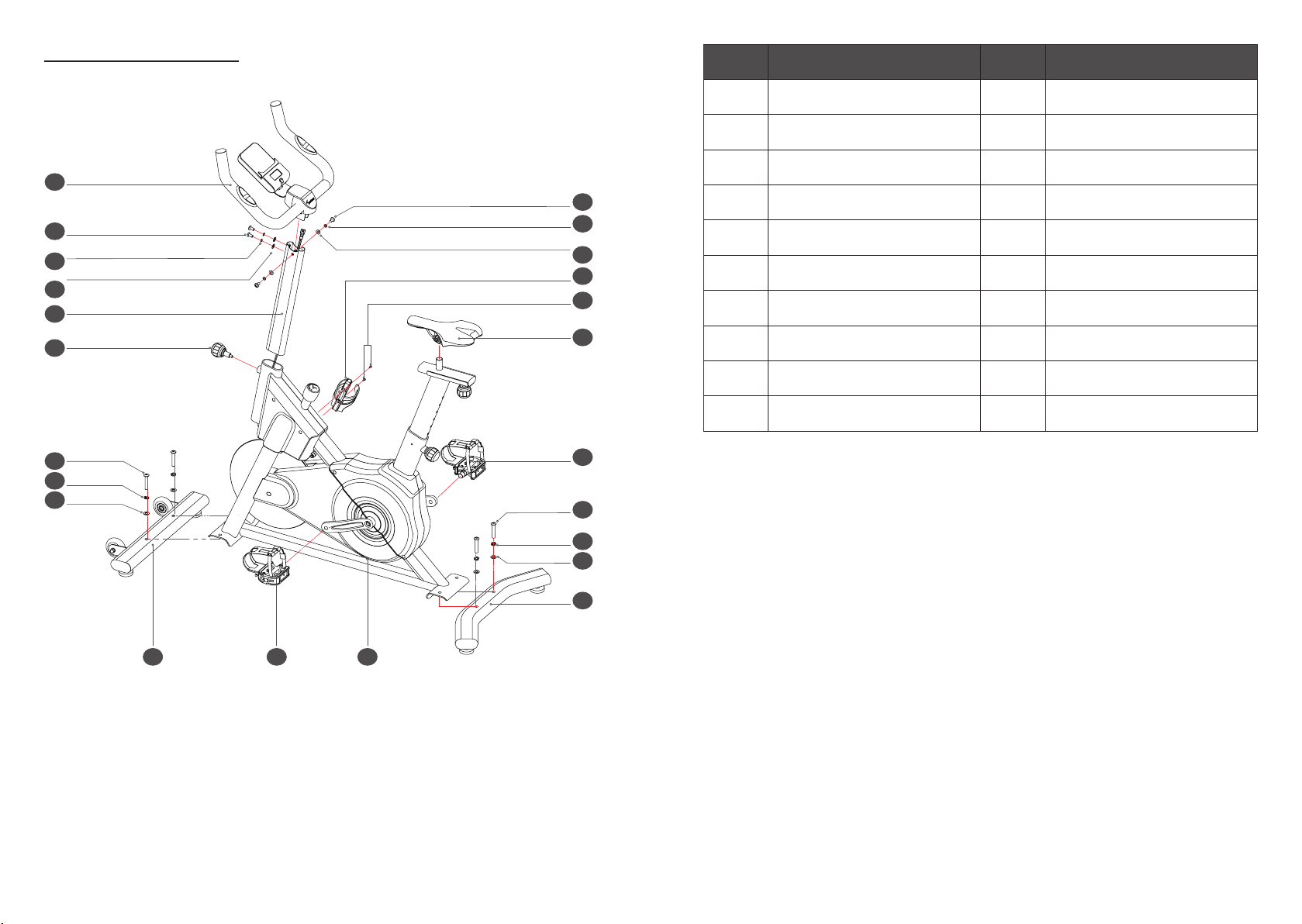
Exploded View Drawing
C
H
I6
F
D
EG1
G2
A
I4
I4
I5
I5
E4
E4
B
A47
I1
I1
I3
I3
I2
I2
Assembly Instructions:
1. Before Assembly
Select the area where you are going to set up and operate your exercise bike. For safe operation, the location must
be on a hard, level surface. Leave a workout area of a minimum 2.4m x 1.8m (94” x 69”).
Take the device out of the box and make sure all the parts are there: It is recommended to carry out the assembly
work with the assistance of another person.
No. Part Name No. Part Name
AMain frame set I2 Spring washer
B Support tube of handlebar I3 Flat washer
CHandlebar set I4 Flat hexagon screw
D Rear stabilizer set I5 Spring washer
E Front stabilizer set E4 Flat washer
F Seat I6 Philip flat screw
G Pedal set I7 Hexagon socket wrench
HBottle holder I8 Outer hexagon wrench
A47 Quick release knob J Instruction manual
I1 Flat inner hexagon screw J1 AAA Battery
2. Basic Assembly Tip
Follow these basic points when you assemble your exercise bike:
* Read and understand the “Safety Precautions” before assembly.
* Collect all the pieces necessary for each assembly step.
* Using the recommended wrenches, turn the bolts and nuts to the right (clockwise) to tighten, and the left
(counter-clockwise) to loosen, unless instructed otherwise.
* When attaching 2 pieces, carefully lift and look through the bolt holes to help insert the bolt through the holes.

1413
I7 1PC
I8 1PC
Assembly Process:
As shown by the circle in the picture, use the hexagon socket wrench (I7) and the outer hexagon wrench (I8) to
remove the auxiliary tubes of the front and rear stabilizer on the main frame set before installation. These two
auxiliary tubes and screws are redundant parts and do not need to be used for subsequent installation.
0.6m/24" 0.6m/24"
0.6m/24"
0.6m/24"
2.4m/94"
1.12m
0.59m
1.8m/69"
No. Part Name Specication Quantity Remarks
AMain frame set 1
E Front stabilizer set 1
I1 Flat inner hexagon screw M10x55 thread 15 2
I2 Spring washer Φ10 2
I3 Flat washer Φ10xΦ20xT1.5 2
I7 Hexagon socket wrench L6+ cross head 1
I1 2PCS
I2 2PCS
I3 2PCS
I7 1PC
STEP1
I1
I3
I2
EA
1. Front Stabilizer Installation
As shown in the gure, put the main frame set on the floor, take the front stabilizer set which has the roller (E), and
prepare the screw (I1), the spring washer (I2), the flat washer (I3). Then place the screw washers in the order of
the installation instructions and tighten them rmly with an hexagon socket wrench (I7).

1615
I1 2PCS
I2 2PCS
I3 2PCS
I7 1PC
STEP2
2. Rear Stabilizer Installation
As shown in the gure, take the rear stabilizer set (D), and prepare the screw (I1), the spring washer (I2), the flat
washer (I3). Then place the screw washers in the order of the installation instructions and tighten them rmly with
an hexagon socket wrench (I7).
No. Part Name Specication Quantity Remarks
AMain frame set 1
D Rear stabilizer set 1
I1 Flat inner hexagon screw M10x55 thread 15 2
I2 Spring washer Φ10 2
I3 Flat washer Φ10xΦ20xT1.5 2
I7 Hexagon socket wrench L6+ cross head 1
I1
I3
I2
D
A
No. Part Name Specication Quantity Remarks
AMain frame set 1
A47 Quick release knob 1
B Support tube of handlebar 1
B1 Pulling rope 1
B
A47
A
B1 STEP3
3. Support Tube of Handlebar Installation
As shown in the gure, there is an electronic connection line on the main frame set, and the support tube of
handlebar is tied with a pulling rope.
3.1. First install the quick release knob (A47) on the main frame set.
3.2. Take the support tube of handlebar(B), tie a section of the pulling rope (B1) to the electronic connection line,
pass the electronic connection line through the support tube of handlebar through the pulling rope, and then
insert the threaded support tube of handlebar into the main frame set.
3.3. Loosen the knob, pull the knob outwards, install the support tube of handlebar (B) to the corresponding hole
of the main frame, and then tighten the knob to x it.

1817
4. Handlebar Set Installation
As shown in the gure, take the handlebar set (C), prepare the screw (I4), the spring washer (I5) and the flat washer
(E4). Then connect the electronic wire on the main frame with the electronic wire on the handlebar set, and gently
install the support tube of handlebar connected with the electronic cable to the main frame set. Then place the screw
washers in the order of the installation instructions and tighten them rmly with an hexagon socket wrench (I7).
No. Part Name Specication Quantity Remarks
AMain frame set 1
CHandlebar set 1
I4 Flat hexagon screw M8X15 4
I5 Springwasher Φ8 4
E4 Flatwasher Φ8.5xΦ16xT1.5 4
I7 Hexagon socket wrench L6+cross head 1
C
E4
I5
I4 I4
I5
E4
A
I4 2PCS
I5 2PCS
E4 2PCS
I7 1PC
STEP4
No. Part Name Specication Quantity Remarks
AMain frame set 1
F Seat 1
I8 Outer hexagon wrench L13+L15 1
I8 1PC
STEP5
F
F
Fa
Fa
A
5. Seat Installation
As shown in the gure, prepare the seat (F). After adjusting to the correct direction, tighten the nut (Fa) on the seat
cushion with an outer hexagon wrench (I8).

2019
6. Left & Right Pedal Installation
The pedal assembly instructions must be strictly followed. If installed improperly, the threads on the pedal or
crank may be damaged. Left and right refer to the direction when you are sitting on the seat.
As shown in the gure, screw the left pedal (G1) marked with the letter (L) to the left crank marked with the letter (L)
in a counterclockwise direction, and screw the right pedal (G2) marked with the letter (R) to the right crank marked
with the letter (R) in a clockwise direction. Finally, tighten them rmly with an outer hexagon wrench (I8).
No. Part Name Specication Quantity Remarks
AMain frame set 1
G1 Left pedal 1
G2 Right pedal 1
I8 Outer hexagon wrench L13+L15 1
I8 1PC
STEP6
A
G1
G2
No. Part Name Specication Quantity Remarks
AMain frame set 1
HBottle holder 1
I6 Philip flat screw M4X8 2
I7 Hexagon socket wrench L6+cross head 1
I6 1PC
I7 1PC
STEP7
A
H
I6
I6
H
7. Bottle Holder Installation
As shown in the gure, prepare the bottle holder (H), Philip flat screw (I6) and hexagon socket wrench (I7). Then
align the bottle holder with the screw hole and tighten it.

2221
8. Console Battery Installation
As shown in the gure, take out the battery (J1) from the manual bag, remove the electronic cover on the back of
the console, install the prepared battery, and then close the battery cover.
No. Part Name Specication Quantity Remarks
AMain frame set 1
J1 AAA battery 2
J1 2PCS
STEP8
J1
A
Instructions for Use
1. Height Adjustment of Handlebar Set
1.1. As shown in Figure STEP1, rst loosen the quick release knob for 2~3 turns, and then lightly hold the
handlebar set.
1.2. As shown in Figure STEP2, hold and pull the knob outward in the direction of the arrow, adjust the handlebar
set to the height of the corresponding hole, gently release the quick release knob, and then tighten them. (Note:
The “STOP” printed on the tube is the maximum adjustment height)
1.3. Schematic diagram of quick release knob adjustment status
STEP1
STEP2

2423
2. Resistance Adjustment
2.1. As shown in the gure, the resistance is adjustable regardless of the grade. Counterclockwise rotation of the
resistance adjustment knob means resistance reduction while clockwise rotation means resistance increase.
2.2. When braking or emergency stop is required, push down the resistance adjustment knob in the direction of
the arrow.
2.3. When not using the exercise bicycle, rotate the resistance adjustment knob to the end in the direction of
resistance increase to lock the flywheel.
3. Height Adjustment of Saddle Support Tube
3.1. As shown in Figure STEP1, rst loosen the quick release knob for 2~3 turns, and then lightly hold the saddle
support tube.
3.2. As shown in Figure STEP2, hold and pull the quick release knob outward in the direction of the arrow, adjust
the saddle support tube to the height of the corresponding hole, gently release the quick release knob, and
then tighten them. (Note: The “STOP” printed on the tube is the maximum adjustment height)
3.3. Adjust the front and rear position of the seat. As shown in the gure, rst loosen the adjust knob of seat for
2~3 turns, adjust the seat back and forth to a suitable position in the direction of the arrow, and then tighten
the adjust knob of seat to x it.
3.4. Schematic diagram of quick release knob adjustment status.
STEP1
STEP2
2625
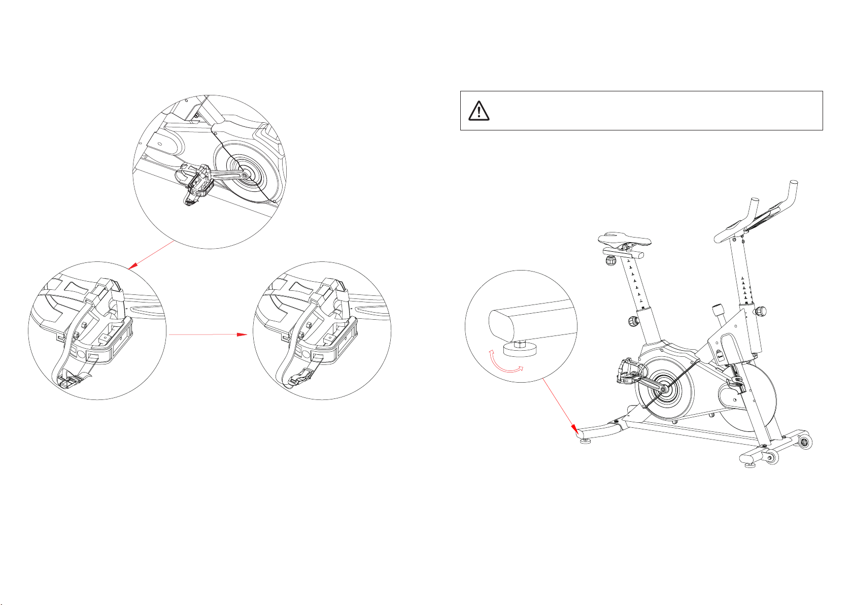
4. Pedal Positioning Tightness Adjustment
4.1. Before using the exercise bike, you need to adjust the tightness of the pedal rope.
4.2. Press the clamp which is on the rope, pull the rope to the proper tightness, and then release the clamp.
Note: Make sure the exercise bike is level and stable before you exercise.
DO NOT adjust the levelers to such a height that they are detached or unscrewed from the exercise
bike to avoid injury to you or damage to the machine.
5.Leveling the Exercise Bike
The exercise bike needs to be leveled if your workout area is uneven. Levelers are found on each side of the
stabilizers. Lift the stabilizer slightly to take the weight off the adjuster, and then turn the knob to adjust the
stabilizer foot.

2827
For safe storage of the exercise bike, remove the batteries. Place the exercise bike in a secure
location away from children and pets.
6. Moving and Storing the Exercise Bike
To move the exercise bike, carefully pull the Handlebars toward you while pushing the front of the bike downward.
Then push the bike to the desired location.
NOTE: Be careful when you move the exercise bike. Abrupt motions can affect the operation of the console.
Parts List

3029
No. Part Name Specication Quantity Remarks
AMain frame set 1
A1 Frame welding 1
A2 Idle wheel axel 1
A3 plastic idle wheel 1
A4 Bearing 608Z 608 2
A5 C-Clip Φ8 1
A6 Wave washer Φ8.2XΦ12XT0.3 1
A7 580J belt/6 grooves 6grooves/580J 1
A8 Crank-L 170 /9/16’teeth 1
A9 Crank R 170 /9/16’teeth 1
A10 Axel wheel welding 1
A11 Aluminum flywheel 1
A12 Axel of flywheel 1
A13 Cylinder hexagon screw M6X20 4
A14 Nylon nut M6 4
A15 Bearing 61900 61900 2
A16 Bearing 6000ZZ 6000ZZ 1
A17 Outer hexagon nut M10X1.25 3
A18 Crank flange welding 1
A19 Belt wheel 1
A20 Cylindar hexagon screw M8X20 6
A21 Nylon nut M8 4
A22 Separate bushing of crank-Short 1
A23 Separate bushing of crank-Long 1
No. Part Name Specication Quantity Remarks
A24 Magnet bracket 1
A25 Magnet 4
A26 Leather 1
A27 Magnet xing seat 2
A28 Knob bolt 1
A29 Domed nut M10 1
A30 Outer hexagon nut M10 2
A31 Plastic-coated nut of knob 1
A32 Resistant adjustment knob 1
A33 Foam of knob 1
A34 Dripping glue sticker of knob 1
A35 Chain cover-L 1
A36 Chain cover-R 1
A37 Stopper plate of chain cover 2
A38 Battery cover 1
A39 Front cover-L 1
A40 Cap of knob 1
A41 Front cover-R 1
A42 Fixing clip 1
A43 Nylon nut M10 3
A44 Bearing 6004Z 2
A45 Flange nut M10X1.25 2
A46 Inner bushing 2
A47 Quick Release knob 1

3231
No. Part Name Specication Quantity Remarks
A48 Nylon nut M6 1
A49 Flat hexagon screw M8X55 1
A50 Nylon nut M8 1
A51 Flywheel bracket -L 1
A52 Flat washer Φ20XΦ24XT1.0 1
A53 Outer hexagon thin nut M20 2
A54 Plunge 3
A55 Philip flat auto screw Φ4X15 19
A56 Philip flat screw M5X10 M5X10 2
A57 Spring washer Φ8 2
A58 Counter Sunk screw M5X15 1
A59 Tension Spring 1
A60 Fixing seat of senser 1
A61 Speed Sensor wire 1
A62 Saddle support tube 1
A63 Sliding welding of seat 1
A64 Oval end cap 2
A65 Adjust knob of seat 1
A66 Sliding plate 1
A67 R- pull pin D2.0 1
I-3 Flat washer Φ10.5xΦ20xT1.5 2
B Support tube of handlebar 1
B1 Pulling rope 1
CHandlebar set 1
No. Part Name Specication Quantity Remarks
C1 Handlebar welding 1
C2 Decor cover of handlebar 1
C3 Foam of handle-R 1
C4 Foam of handle-L 1
C5 Round tube cap Φ31.8 2
C6 Pulse pad 2
C7 Philip flat screw M5X10 2
C8 Philip flat auto screw Φ4X15 4
C9 Thread fastener 1
C10 Console 1
C11 Pulse wire 2
D Rear stabilizer set 1
D1 Rear stabilizer welding 1
D2 Outer hexagon nut M10 2
D3 Stabilizer pad M10 M10 2
D4 Oval end cap of stabilizer 2
E Front stabilizer set 1
E1 Front stabilizer welding 1
D2 Outer hexagon nut M10 2
D3 Stabilizer pad M10 M10 2
D4 Oval end cap of stabilizer 2
E2 PU wheel 2
A4 Bearing 608z 608 4
E3 Flat inner hexagon screw M8X40 2
3433
No. Part Name Specication Quantity Remarks
E4 Flat washer Φ8.5XΦ16XT1.5 Φ8.5XΦ16XT1.5 4
E5 Domed nut M8 2
F Seat 1
G Pedal set 1
G1 Pedal-L 1
G2 Pedal-R 1
HBottle holder 788E006xP0QR000 1
I Blister board set 1
I1 Flat inner hexagon screw M10X55 thread 15 4
I2 Spring washer Φ10 4
I3 Flat washer Φ10.5XΦ20XT1.5 4
I4 Flat hexagon screw M8X15 4
I5 Spring washer Φ8 4
E4 Flat washer Φ8.5XΦ16XT1.5 4
I6 Philip flat screw M4X8 2
I7 Hexagon socket wrench L6+ 1
I8 Outer hexagon wrench L13+L15 1
A47 Quick released knob 1
J Instruction manual 1
J1 AAA Battery 2
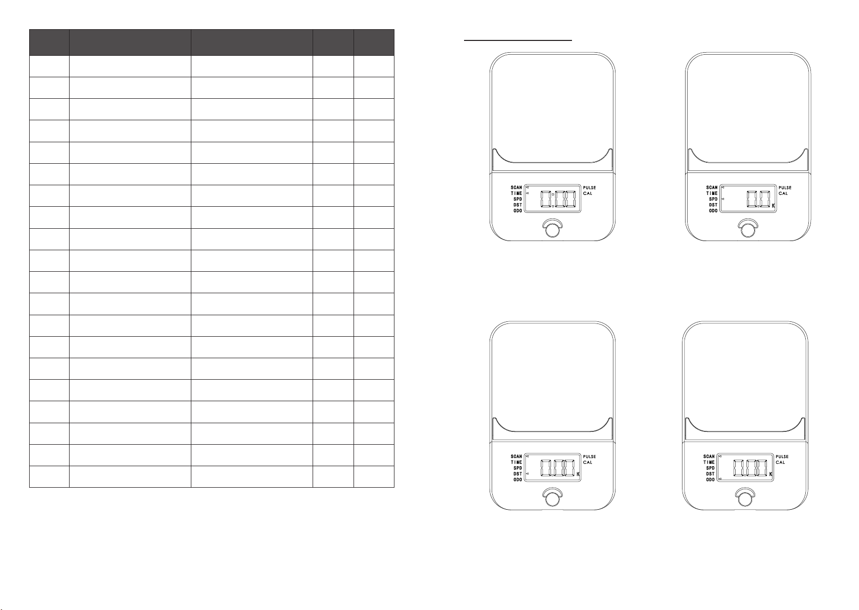
Console Operations
When the triangle indicator at the SCAN position flashes,
the console is in working condition. Press the MODE
button to make the triangle indicator light at the TIME
position. When the triangle indicator at the TIME position
flashes, the displayed data represents the total time from
the start to the end of the movement.
When the triangle indicator at the SCAN position flashes,
the console is in working condition. Press the MODE
button to make the triangle indicator light at the DST
position. When the triangle indicator is at the DST
position, the displayed data indicates the total distance
from the start to the end of the exercise.
When the triangle indicator at the SCAN position flashes,
the console is in working condition. Press the MODE
button to make the triangle indicator light at the ODO
position. When the triangle indicator is at the ODO
position, the displayed data indicates the total mileage of
the exercise.
When the triangle indicator at the SCAN position flashes,
the console is in working condition. Press the MODE
button to make the triangle indicator light at the SPD
position. When the triangle indicator is at the SPD position,
the displayed data indicates the current exercise speed.

3635
When the triangle indicator at the SCAN position flashes,
the console is in working condition. Press the MODE
button to make the triangle indicator light at the PULSE
position. When the triangle indicator light is at the PULSE
position, hold the handle pulse sensor with both hands
for about 3 seconds. The display window will show the
natural heart rate value. (Note: Heart rate monitoring
systems may be inaccurate. Over exercise may result in
serious injury or death. If you feel faint, stop exercising
immediately.)
When the triangle indicator at the SCAN position flashes,
the console is in working condition. Press the MODE
button to make the triangle indicator light at the CAL
position. When the triangle indicator is at the CAL
position, the displayed data indicates the total energy
burned from the start to the end of the exercise.
Press and hold the MODE button for 3s to reset the
console, and the content displayed in the window is as
shown in the gure.
HEARTBEAT MEASUREMENT:
WARNING: Heart rate monitoring systems may be inaccurate. Over exercise may result in serious injury or death.
If you feel faint, stop exercising immediately.
When the pulse pad detects the user's heartbeat, the triangle indicator on the console flashes at the PULSE
position. After a short period of time, the corresponding value will be displayed.
USING THE PULSE FUNCTION:
The PULSE/SPEED Window on your Computer works in conjunction with the pulse pad on both handrails. When
you are ready to read your pulse:
1. Place both hands rmly on the pulse pad. For the most accurate reading, it is important to use both hands.
2. When the user's heartbeat data is detected, the triangle indicator at the PULSE position will flash. Your
estimated heart rate will display in the PULSE window approximately 10 seconds after you hold the pulse pad.
3. This estimate is not exact and persons with medical conditions and/or a specic need for accurate heart rate
monitoring should not rely on the estimations provided.
Warning - The heart rate monitoring system may be inaccurate.Excessive exercise may cause serious physical
damage or sudden death.If you feel dizzy or hard breath, stop exercising immediately.
Before starting an exercise program, you must know your maximum heart rate.
The approximate maximum heart rate value of a user is calculated as follows: MHR = 220 – Age.
To check the heart rate range and select the exercise program, the user wishes to perform, look at the following
diagram.
Warning: The user's heart rate value must not exceed 90% of the maximum heart rate valu

3837
App Usage
A: Download the APP
Search and download "Sportneer" in the App Store or Google play (IOS12 above,
Android 6.0 above)
B: Registration & Connection
1. Open the "Sportneer" APP.
2. New users choose "Sign up" (registered Sportneer APP users choose "Sign in" and log in with registered email).
3. Check the verication code received by the registered mailbox, enter the verication code for email verication;
After successful verication, it will automatically jump to the "Set a password" page, and then please set the
user password.
4. After the user password is set, click "Finish" to enter the "Complete Information" page; Users set "Nickname",
select "Gender" "Birthday", click "Continue" to enter the "Record weight" pop-up box, and select "Manual record"
(If you have a Sportneer body fat scale, please select "Body fat weighting"). Finally, enter the "Your Weight And
Height" page.
5. Set "Weight And Height", click "Start Sportneer" to enter the "Training Types" page.
6. Select the preferred category in the "Training Types" menu, click "Save" and enter the "Sportneer APP"
homepage.
C. Equipment Connection & Course Training
1. Select "Training course" in the Tab bar at the bottom of the Sportneer APP homepage to enter the homepage.
2.1 Select "My" in the APP menu bar, open "My Devices", and select "+".
2.2 Select "Courses" in the APP menu bar, select the "Exercise Bike" course, and enter the "Device Search" menu
after selecting the detailed course.
3. Please follow the APP prompts to step on the exercise bike and keep working conditions to search for the
exercise equipment for connection.
Maintenance & Cleaning
Care has been taken to assure that your equipment has been properly adjusted and lubricated at the factory.It
is not recommended that the user attempt service on the internal components.Instead, seek service from an
authorized service center.However, you may clean the outer surface by using a soft cloth dampened with warm
water.Do not use aerosol sprays or pump bottles as they may deposit sediments upon the console surface.The
use of harsh chemicals will destroy the protective coating and cause a static build-up that may damage some of
the components.
Manufacturer:
Thousandshores Deutschland GmbH, Bredowstraße 17, Hamburg 22113, DE
FCC Statement
Changes or modications not expressly approved by the party responsible for compliance could void the user's
authority to operate the equipment.
This equipment has been tested and found to comply with the limits for a Class B digital device, pursuant to Part
15 of the FCC Rules. These limits are designed to provide reasonable protection against harmful interference in a
residential installation. This equipment generates uses and can radiate radio frequency energy and, if not installed
and used in accordance with the instructions, may cause harmful interference to radio communications. However,
there is no guarantee that interference will not occur in a particular installation. If this equipment does cause
harmful interference to radio or television reception, which can be determined by turning the equipment off and
on, the user is encouraged to try to correct the interference by one or more of the following measures:
-- Reorient or relocate the receiving antenna.
-- Increase the separation between the equipment and receiver.
-- Connect the equipment into an outlet on a circuit different from that to which the receiver is connected.
-- Consult the dealer or an experienced radio/TV technician for help.
This device complies with part 15 of the FCC rules. Operation is subject to the following two conditions (1)this
device may not cause harmful interference, and (2) this device must accept any interference received, including
interference that may cause undesired operation.
Table of contents
Popular Exercise Bike manuals by other brands


Sunny Health & Fitness
Sunny Health & Fitness SF-B121021 user manual

Monark
Monark 827E instruction manual

Stamina
Stamina 1310 owner's manual

American Fitness
American Fitness SPR-BK1072A owner's manual
 Service manual")
Cateye
Cateye CS-1000 (CYCLO SIMULATOR) Service manual

BH FITNESS
BH FITNESS H9158H Instructions for assembly and use