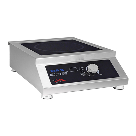
Spring USA MAX Induction SM-251-2CR User manual

Installation &
Operation
Manual
By
Models: SM-251-2CR
&
SM-253-2CR
(International)
127 Ambassador rive
Suite 147
Naperville, IL 60540-4079
Phone: 630-527-8600 Fax: 630-527-8677
Email: springusa@springusa.com
Website: www.springusa.com
1
8
Safety Precautions & Key Points:
Cabinet Ventilation must be provided. The inside temperature of the
cabinet must not exceed 90°F / 3 ° C. Both vents & circulation fans
must be installed in order for your induction range to operate properly.
Failure to install proper ventilation automatically voids your warranty.
Actual range temperatures may vary due to a number of variables, such
as ambient temperature in the immediate surrounding area, content &
volume of food being heated or cooked, & whether or not you are using a
lid on the serving vessel.
-------------
Never attempt to service any part of your MAX Induction®Range on
your own. Contact our Service Department by calling (1) 630-5 7-8600.
Attempting to service your Induction Range on your own, or through an
unauthorized repair facility automatically voids your warranty. For
service forms, visit the Spring USA website.
For Limited Warranty Information, visit www.springusa.com
Note:
This equipment uses, generates and can radiate radio frequency energy.
If not installed correctly and used in accordance with the instructions,
may cause harmful interference to radio communications. Users or
guests with Pacemakers should contact their health care professional
prior to using this product.
The Evolution of Intelligent Design®

efore You egin:
www.springusa.com
630-527-8600
Filter Maintenance for Double MAX Induction®7
Read the following instructions in their entirety. Use proper cookware.
Your cookware must be induction-ready.
Check your ventilation. Your MAX Induction®Range must have the
proper ventilation in order to operate correctly. There must be at least 10”
of space available under a mounted induction range. Cabinets housing the
induction ranges should have both vents & circulation fans installed. The
inside temperature of the cabinet must not exceed 90°F / 3 ° C.
Ensure that you have dedicated power to the installed location.
Refer to the grid on Page 6 for Electrical Specifications.
Your MAX Induction®Double Induction Range is equipped with two
grease filters in order to protect the electronics from contaminants.
Grease filters should be removed & inspected daily. To clean the filters,
slide the filters out of the track on the bottom of the induction range. Wash
thoroughly with mild liquid detergent. Shake remaining water out of the
filter & let is stand until dry. Once completely dry, reinsert into the tracks
of the induction range. Filters are not dishwasher safe, and must be
washed by hand.
Once the filter becomes difficult to clean, or begins to show ware, replace
with a new filter. Never operate the induction range without grease filters
installed. New filters can be ordered by contacting Spring USA directly.
Induction Range Error Codes:
Review your dedicated power
requirements. Each range must
operate with the power required on
Page 6.
Range will not turn on. Range is
experiencing temporary voltage
overload or is not on its own,
dedicated circuit.
E3
Remove the cookware from the
range and let the range cool. Make
sure the vents are clear. Verify you
are using induction-ready
cookware. Once the range has
cooled, restart.
The range has overheated.
E2
Clear vents, let range cool down,
then restart. If error message
continues, your range needs to be
serviced.
Range has overheated due to
blocked ventilation and has shut
down the range.
E1
Place an induction ready pan on
the range.
Induction range does not sense
induction-ready cookware has
been placed on the glass surface
E0
SolutionCauseError
Suitable Serving Ware:
Your MAX Induction®Range works with induction-ready serving vessels.
Visit the Spring USA Website for a full line of induction-ready,
professional serve ware.
Serving pieces must have a flat bottom, in order to make full contact with
the countertop.
Serving pieces that are footed, or that have a raised ridge, are not for use on
this system, as they cannot make full contact with the counter surface.
Vessels must have a diameter greater than 9”.
Glass Cookware is not suited for use on your induction warming system.
Serving vessels must be centered on the induction warmer for optimal
heating and performance.
www.springusa.com
Stainless Steel Multi-Ply
Cookware
Carbon Steel
Aluminum Cookware with
Induction Disc Cast Iron
Convertible Buffet Servers Aluminum Tray With
Induction Disk

For a built-in applications, your counter or table thickness must not
exceed ”. Your MAX Induction®Range must have the proper
ventilation in order to operate correctly. There must be at least 10” of
space available under a mounted induction range. Cabinets housing the
induction range should have both vents & circulation fans installed. The
inside temperature of the cabinet must not exceed 90°F / 3 ° C.
To mount your MAX Induction®Double Range, you must first remove
the control panel (refer to page 4 for instruction). Place the template of
the induction range on the surface you are preparing for the install.
Center the template, allowing a minimum of 4” of countertop space on
each side of the induction range. The template measures 6.38” (670
mm) long x 13.39” (340 mm) wide.
Once you insert the induction range into the cut out, the edge of the
range will sit 0.5” (1 .75 mm) above the surface of the countertop.
Apply a thin bead of 100% rubber silicone sealant around the surface
perimeter of the mounted induction range.
Mounting Your Induction Range:
4 5
Double MAX Induction®Range (Countertop Use):
Cabinet ventilation (vents & circulation fans)
must be provided. Inside temperature of the
cabinet must not exceed 90°F / 3 °C.
Control Panel adjusts 1/ ”
to 3/4” depending on the
thickness of plywood.
Remove your MAX Induction®range from the packaging and inspect all
parts. If the ceramic glass surface is cracked or damaged, do not install the
range. Contact your supplier for a replacement range.
Removing the Control Panel:
Your MAX Induction®Double Range can be used as a countertop unit, or
can be built into a countertop. If you’re using it as a countertop unit, the
control box can be mounted in the center of the two ranges, or can be
removed & placed on the left end of the induction range assembly.
To remove the control box assembly, turn the induction range on its side.
Remove the two locking screws which connect the control box to the range.
Pull down & remove the control box from the induction housing. The
control box will be connected to the induction range by a cable. To remove
the cable from the range, loosen the two thumb-screws & pull out the
connector.
The control panel can now be connected to the side of the double induction
range. Remove the small metal housing from the side of the range. This
housing can be placed over the center opening to prevent dust & grease
from corroding the connector. Screw the cable connector to the side
connection. Tighten the screws, insert locking teeth into the mounting slots
& mount two locking screws into the bottom of the induction range
housing.

Your MAX Induction®Range is designed to operate in two modes:
“Cook” or “Temp”.
“Cook” Mode offers you high-speed heating, used for omelet stations,
pasta bars or demonstration cooking.
“Temp” Mode offers you thermostatically controlled holding temperatures
for use with buffets or pastry work. The LED display allows for more
accurate cooking.
In “Cook” Mode:
An ‘E0’ code will flash until suitable cookware is placed on the glass
surface of the range.
The LED panel will display a two-digit number indicating the power
level. Power levels run from 1 thru 0.
As a safety precaution, if no cookware is placed on the induction
range plate after 2-1/2 minutes, the unit will shut off.
Once suitable cookware has been placed on the glass induction plate,
the unit will continue to cook until the range is manually shut down,
or the mode is changed over to “Temp” mode.
Note: As a safety precaution, make sure you have at least 4” of space at
the back of the Induction range. Induction ranges need ventilation to
operate efficiently.
In “Temp” Mode:
An ‘E0’ code will flash until suitable cookware is placed on the glass
surface of the range.
The LED panel will display a three-digit number indicating the
temperature setting. To increase the temperature setting, turn the dial
clockwise. To decrease the setting, turn the dial to the counter-
clockwise.
The induction range will continue to warm the food until the set
temperature has been reached. Once the temperature has been
reached, the range will maintain that pre-selected temperature setting.
Temperature settings in “Temp” mode, in Fahrenheit are:
110°, 1 0°, 130°, 140°, 150°, 160°, 170°, 180°, 190°, 00°, 0°,
40°, 60°, 80°, 300°, 3 0°, 340°, 360°, 380° & 400°.
Celsius: 43°, 49°, 54°, 60°, 66°, 71°, 77°, 8 °, 88°, 93°, 104°, 116°,
1 7°, 138°, 149°, 160°, 171°, 18 °, 193° & 04°.
Mounting of the Control Panel:
To install the control panel, use the template provided. Place the template
on a plane or panel, perpendicular to the MAX Induction®Range,
centering it to the range whenever possible.
The control panel cut out should measure 14-1/8” long x 5-1/8” wide.
Place the control panel into cutout hole. Using the metal bracket
provided, secure the control panel into place. The control panel is meant
to adjust ½” x ¾” thickness, depending on the surface it is being mounted
to. Connect the control box cable to the induction range.
6How To Operate: 3
Electrical Specifications:
Plug & receptacle to be supplied
by Customer ~ Spring USA will
provide a wiring diagram. The
cord must be correct, based on
voltage & amperage per
Country’s Code requirements.
500W x
50 – 60 Hz
0- 40 V
0.8 Amps
SM- 53- CR
NEMA 6-30P 6’ Cord500W x
50 – 60 Hz
08- 0 V
1.7 Amps
SM- 51- CR
Plug TypePeak
Power
Voltage /
Amps
Model #
Table of contents
Other Spring USA Cooktop manuals
Popular Cooktop manuals by other brands
Omega
Omega OG30XA Installation and operating instructions
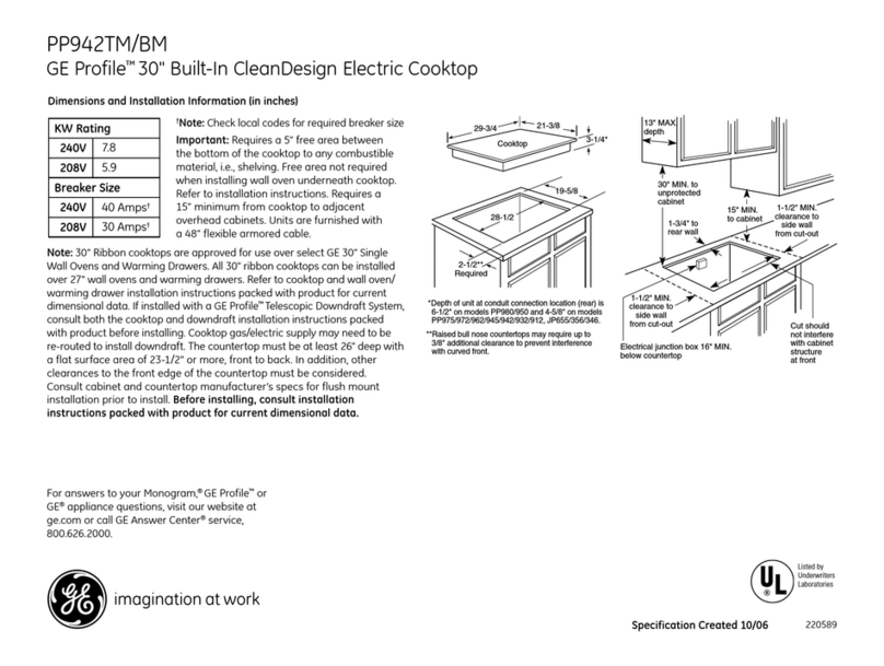
GE
GE Profile PP942 Dimensions and installation information
KitchenAid
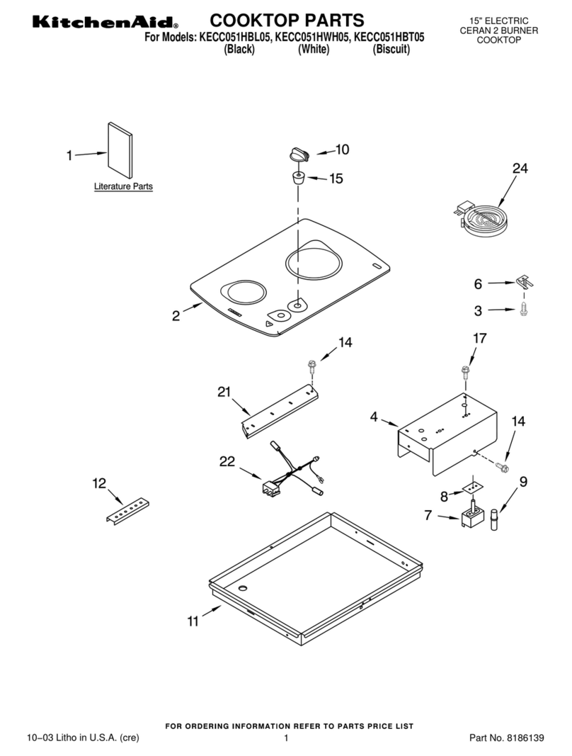
KitchenAid KECC051HBL05 parts list

Kenstar
Kenstar BRIO KIB19BP3-CMG Service manual
Bourgini
Bourgini 10.1012.00.00 instructions
Dometic
Dometic Hot and Cooking CVI1350 Installation and operating manual

KitchenAid
KitchenAid KGCP462KSS - 36" Gas Cooktop parts list

Fisher & Paykel
Fisher & Paykel CG705 Series Installation instructions and user guide

Gaggenau
Gaggenau CE 491 instruction manual
Frigidaire
Frigidaire GLEC30S9E - 30 in Smoothtop Electric Cooktop installation instructions
Eurolux
Eurolux ECH4 TC3 FV installation manual

Jenn-Air
Jenn-Air JGC1530BS Use & care guide
