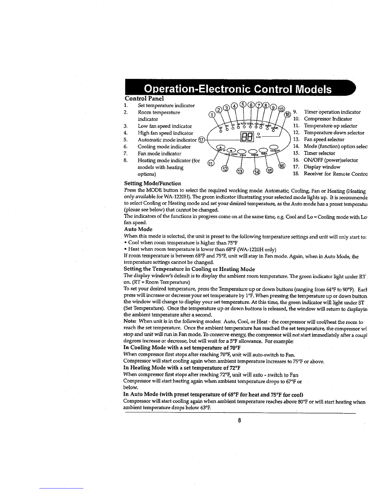
SPT WA-1220M User manual

WA-1220H, WA-1220E
TAB[
It isimportantthatyou read
these ins'_uctionsbefore using
yournew purchaseand we
_TOng[yrecommend thatyou
keepthem in a safe pfa_efor
future reference.

THANK YOU.................................................................................................................... 2
Energy Saving Tips................................................................................................................................ 2
SPECIFICATIONS.......................................................................................................... 3
BEFORE USE ..................................... ;............................................................................ 4
PARTS ............................................................................................................................ 5
Acc_orie_ ............................................................................................................................................ 5
INSTALLATION .................................................................... :...................................... 6
Mounting the Unit ................................................................................................................................ 6
Mounting the Exhaust Pipe................................................................................................................... 7
INSTALLATION OF CARBON FILTER ..................................................................... 7
OPERATION- ELECTRONIC CONTROL MODELS ............................................... 8
Control Panel ........................................................................................................... 8
Setting ModelFunction .................................................... ........................................... 8
Auto Mode ........................................ ...................................................................... 8
Setting the temperature ............................................................................................... 8
•Setting Fan Speed...................................................................................................... 9
Setting the timer ............... ......................................................... ,.............................. 9
RegulatingAifflow Direction ........................................................ ............................... 9
OPERATION- MECHANICAL CONTROL MODELS ........ :.......................... 10
Tun_ing OtdOff. ................................................................................................................................. I0
Setting Function 1 Ventilation Speed ................................................................................................... 10
Setting the Temperature ........................................................................................................... _.......... 10
Setting the Timer ................................................................................................................................. 10
DRAINAGE ........................................ ............_................................................................ 11
By Draining into a Container ......................................................................... ....................................... I1
By Water Tube (continuous drainage) ........:....................... :................................................................ 11
MAINTENANCE ................................................................ i......................................... 12
Cleaning the Housing ........................................................................................................................... 12
Cleaning the Filter ................................................................... ;................................. 12
End of Season Storage .......................................................................................................................... I2
Storing the Power Cord .............................................................................................. 12
TROUBLESHOOTING ................................................................................................... 13
DEFECTIVE NOTICE ................................................... ................................................ 14
YOUR GUA._RANTEE ..................................................................................................... 15

Thank you for choosing the portable air conditioner from SPTusA, a leading brand in indoor
air tTeatment. We would like you to enjoy the many benefits this unit offers, so please take the
time to read this manuaI carefully and take hill advantage of the many advanced features that
your SPTusA Air Conditioner offers you.
SPTusA has specialized in complete h_door environment control, manufacturing world-class
air conditioners, dehumidifiers and air purifiers with innovative technology.
In designing these advanced products, we have listened carefully to our customers and
have passed their views on to our research and development laboratories.
We wish you many years of enjoyable use.
After reading this manual, please keep it in a safe place for future reference.
Energy Saving Tips
• Please use the unit in the recommended room size. (Refer to SPECIFICATIONS ).
• Do not locate the air conditioner where furniture or other objects can obstruct the
airflow.
• Keep blinds/curtains closed during the sunniest part of the day.
• Close the fireplace damper and floor or wal! grills so that coot air does not escape
through the chimney or ductwork.
• Keep the filters clean.
set the unit to maximum cooling and high speed fan inifiall_ then adjust the unit to a
comfortable setting.
NOTE: It is recommended to turn on the air conditioner when the room temperature is
around 75°F. Do not wait until the room is excessively hot.

Model Number
Power Consumption
Humidity Removal Capacity
Recommended Room Size*
Power Supply
Compressor
Fan Speed
Timer
Thermostat
Net Weight
Dimensions
Working Temperature
WA-1220E
WA-1220M
12,000 gTUihr
N/A
950W /9A
65 pts. [Day
400 sq, ft.
120V /60Hz /1Phase
Rotary
R-22 R-22
2 2
WA-I220E: 1-12hours 1-12 hours
WA-1220M: 1-8 hours
64OF- 900F
65 lbs.
15"W x16"D x 30"H
Cooling: 64°F to 110QF
.WA-1220H
12,000 BTUihr
12,000 BTU/hr
950W /9A
65 pts. /Day
400 sq. ft.
...........i" "' ' ''"
120V 160Hz / 1 Phase
Rotary
64OF- 900F
68 lbs.
15"W x16"D x 30"H
Cooling: 64°F to lt0°F
Heating: 41oF to 810F
REMARKS:
1. The data may vary, please refer to the rating label on the back on the back of the unit.
2. The above conditions are measured at:
Cooling -Indoor: RT 81°F, RH 60%
Heating - Indoor: RT 68_F, RH 60%
*Uninsulated rooms such as sunrooms, garages, or attics should be less than 400 sq. ft.

Important!
• Transport the unit in artupright position only, or leave it in an upright position for
at least 2 hours before first use.
•Always place the unit on an even surface (Figure 1).
*Make sure the unit is connected to a correctly grounded power supply /_
(refer to the rating label located at the back of the unit).
i
g _ unit will cool when the room temperature is between 64°F and 110°F depending on the
thermostat setting.
An opening in awindow or wall is required to accommodate the exhaust
hose (kit supplied) to expel the warm air,
Do not cover or obstruct the appliance inlet or outIet grilles (Figure2):
To avoid the risk of shock, the product should never be used in bathrooms,
shower rooms or in any other steamy or wet areas.
Do not sit or place objects on the unit
Do not touch the unit with wet/damp hands or when standing
barefoot.
• Avoid all contact with chemical based materials,
• The filter must be used with the product at all times. When removing for
cleaning, always disconnect the unit from the mains first,
• Turn off the appliance when not in use.
• At the end of each season all water must be drained and the unit
and filters cleaned before storage.
•Drainage of the water container is required before moving the unit or putting
it into storage.
• If the electric socket is different from the plug provided, have a professionally
•qualified electrician replace the plug with a suitable one. Avoid the use of
adaptor plugs, multiple sockets and/or extension leads; if their use is necessar_ ensure
that they conform to the current safety regulations.
•Do not pull the supply cable or place it near a source of heat; always unroll it completely to avoid
the possibility of dangerous overheating.
0If the supply cord is damaged, it must be replaced by the service agent or a
similarly qualified person.
THE MANUFACTURER DISCLAIMS ANY RESPONSIBILITY IF THE ABOVE INSTRUCTIONS ARE
NOT FOLLOWED.
Fig. 2

1. ControlPanel
2. Cooling Air Outlet
3. Handle
4. Castors
Accessories
5. Air Filter
6, Air Inlet
7. Exhaust Air Outlet
8. Cord Hanger
9. Water Stopper (Rubber Plug inside)
10.
1t.
Adaptor- for insertion over the hose
into the back of the air conditioner
Exhaust Hose
Length: 14" - 60"
Diameter: 4.75"
12. Foam Strip -for filling the open window space
and with a hole for connection to the exhaust
hose. __
Dimension:T'x24.5x.75"
13. Foam Strip- for filling the open window space
Dimension:T'x24.5x.75"
14. Round Connector - to be used between hose
_dwindo_ki_orbetweenhose_d _ _ ,.-.,
15. Cap -for round connector ,,5-A_ _
16. Remote Control
(Electronic control models only)

Mountingthe unit
This unit is a portable air conditioner. It can be moved from room to room so that the
cooling can follow you anywhere. Fitting the exhaust hose is eas34 through a window or
wall
Please refer to either of the following ways:
1. Using the foam strips
• Connect the supplied foam strips with the exhaust pipe, let the hot air flow to the outside.
•Should the foam strip(s) be too large, cut off the extra part to fit the window.
2. Using the through the Wail Connection
• Make a hole (5" in diameter) in the wail to fit the supplied round connector.
•Fit the hose directly to the round connector.
• When the hole is not in use, use the cap for the round connector to cover the hole.
8

Mounting the exhaust pipe
• The supplied exhaust hose can be
extended from !foot to 5 feet
for mounting. It is recommended that
you use the shortest possible length of hose.
*Take care to prevent any kink or bend in
the middle of the exhaust hose, as this
will trap hot exhaust ai_;
which will radiate back into the room,
WARNING!
The length of the exhaust pipe is specially
designed according to the specification of this
product.
Do not replace or extend it with your own hose
as this could cause the unit to malfunction.
1. Remove the filter frame from the unit.
2. Separate the filter from the filter frame.
3. Remove the active carbon filter from
its plastic bag.
4. Insert the active carbon filter into
thefilterframe.
5. Fix the filter by reassembling the
fixer Onto the filter frame.
6. Re-fit the filter frame
inside the unit.
7, It is recommended to replace the
carbon filter every 3to 6 months.

Control Panel
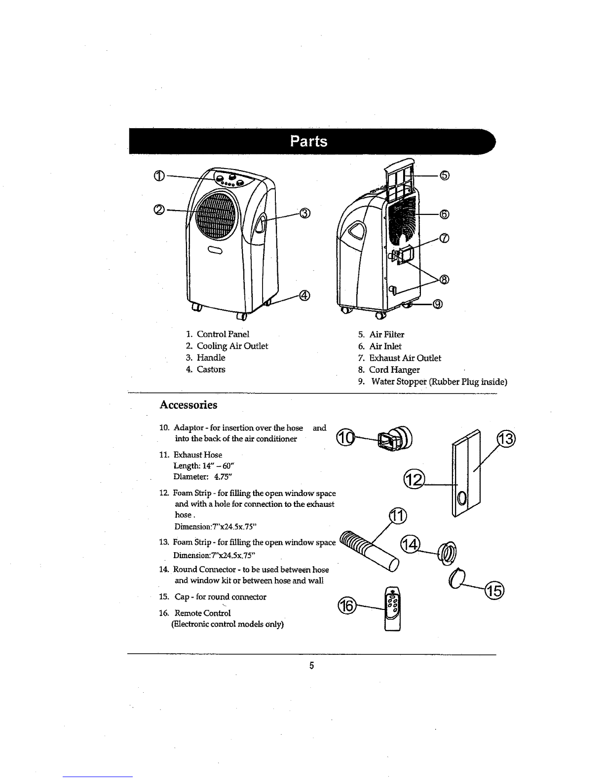
1. Set temperature indicator
2. Room temperature 9. Timer Operation indicator
indicator 10. Compressor Indicator
3, Low fan speed indicator 11. Temperature up selector
4, High fan speed indicator 12. Temperature down selector
5. Automatic mode indicator @ 13. Fan speed selector
6. Cooling mode indicator 14. Mode (function) option selec_
7. Fan mode indicator 15. Timer selector
8. Heating mode indicator (for 16. ON!OFF (power)selector
models with heating 17. Display window
options) 18. ReceiVer for Remote Contro
Setting ModedFunction
Press the MODE button to select the required working mode: Automatic; Cooling, Fan or Heating (Heating
only available for WA-1220H). The green indicator illustrating your selected mode lights up. It is recommende
to select Cooling or Heating mode and set your desired temperature, as the Auto mode has a preset temperatu_
(please see below) that cannot be changed.
The indicators of the functions in progress come on at the same time, e.g. Cool and Lo =Cooling mode with Lo_
fan speed.
Auto Mode
When this mode is selected, the unit is preset to the following temperature settings and unit will only start to:
•Cool when room temperature is higher than 75°F
•Heat when room temperature is lower than 68°F (WA-1220H only)
If room temperature is between 68°F and 75°F, unit will stay in Fan mode. Again, when in Auto Mode, the
temperature settings cannot be changed.
Setting the Temperature in Cooling or Heating Mode
The display window's default is to display the ambient room temperature. The green indicator light under RT:
on. (RT = Room Temperature)
To set your desired temperature, press the Temperature up or down buttons (ranging from 64°F to 90°F). Earl
press will increase or decrease your set temperature by I°Fo When pressing the temperature up or down button
the window will change to display your set temperature. At this time, the green indicator will light under ST
(Set Temperature). Once the temperature up or down buttons is released, the window will return to displayin
the ambient temperature aftei: asecond.
Note: When unit is in the following modes: Auto, Cool, or Heat - the compressor will cool/heat the room to
reach the set temperature. Once the ambient temperature has reached the set temperature, the compressorwi
stop and unit will run in Fan mode. To conserve energ_ the compressor will not start immediately after acoup]
degrees increase or decrease, but will wait for a 5°F allowance. For example:
In Coolii_g Mode with a set temperature of 70°F
When compressor first stops after reaching 70°F, unit will auto-switch to Fan.
Compressor will start cooling again when ambient temperature increases to 75°F or above.
In Heating Mode with a set temperature of 72QF
When compressor first stops after reaching 72°F, unit wil! auto - switch to Fan
Compressor will start heating again when ambient temperature drops to 67°F or
below.
In Auto Mode (with preset temperature of 68°F for heat and 75°F for cool)
Compressor will start cooling again when ambient temperature reaches above 80°F or will start heating when
ambient temperature drops below 63°F.

setting The Fan Speed
Press the SPEED button to choose the fan speed you require, high or low, The indicator of
high or low fan wilt light up at the same time.
If the unit is in AUTO mode, it will select the fan speed automatically according to the
ambient temperature (the related indicators, cool, fan or heat will light up), at this firae the
fan speed switch is invalid.
Setting the Timer
Press the TIMER button to set the operating hours you desire (1 to 12 hours, the timer
indicator will light up). When the set time has elapsed, the machine will turn off automatically.
27ne display window will show the hour(s) you set as you press the TIMER button, If the timer
button is not pressed, the unit wii1 work continuously.
By pressingthetimerbuttonbut withoutturaingon theunit,you can ERE-SET thetime forthe
machine towork. For example, ifyou pressthe timerto'2',theunitwillcome on automatically
after2hours.
All the above fimctions can also be performed with the supplied remote control This remote
control reqTaires 2 AAA batteries to operate.
Regulating the Airflow Direction
Turn the roller on the air vent to control
the airflow direction/rom the vertical louvers.
NOTICE!
• The compressor will start approximately 3 minutes after the unit is turned on
(this will help prolong the life of the compressor). After switching the unit off, please wait at
least 3minutes before turning the unit back om
• The cooling system will switch off if the room temperature is lower than set. The fan, however, keeps
working at the set level. If the ambient temperature rises above the chosen level +5 °, the cooling will
resuJlle.
In heating mode, the compressor will switch off if the room temperature is HIGHER than the one
set. As the room temperature drops below the chosen temperature -5"F, heating wi]l resume. (The
fan keeps working at the set level)
•This machine is equipped with an ANTI-FROST function. While us'rag the heating function during
low temperatures, sometimes the heating will stop for awhile to melt the Lnternal frost, lhrhen this
occurs, just wait for heating to resume.
• As you switch on the heating, the fan will stop for 15-20 seconds prior to unit start.

WA-1220M
1. Power indicator
2. Fan operating indicator
3. Cooling operating indicator
4. Full water indicator
5. Thermostat
6. Speed switch with options for -LOW FAN,
HIGH FAN, LOW COOL, I-UGH COOL
7. Timer (1-8 hours) as well as ON/OFF switch
Turning ON/OFF
Set TIMER to ON for continuous operation
(the unit will operate as Iong as it is not turned off).
Power indicator comes on.
To turn off the unit, turn the TIMER to the OFF position
Setting Function /Ventilation Speed
WA-1220M
Turn the speed switch to select the required setting: LOW
FAN, HIGH FAN, LOW COOL, HIGH COOL, SPEED OFF
Setting the Temperature
Turn the THERMOSTAT to regulate the temperature you
desire: range 64°F to 90°F,
Setting the Timer
Turn the TIMER to the desired operating time (1 to 8 hours).
When the set time has elapsed, the machine will shut off
automaficaUy.
Low Cool
SPEE
Low Fan
High Fan
10

During the process of cooling or heating, some water willbe extracted from the air
into the unit. Most of this water is used to cool the unit and make it run more
efficiently. This is a feature not found in most Portable Air Conditioners. If the unit is
operated in VERY HUMID air, water will collect in the container inside the unit. tf the
water container is full, the compressor and fan will stop. The POWER indicator will
blink to inform you to empty the internaI container. To make the cooling function
work again, please empty the water by one of the following methods:
By the Draining into aContainer (Use a Shallow Container or Dish)
1. Turn off the unit.
2. Position a fiat container or dish under the drain hole. Do not allow the water to dr!
corltinuously into the container, as it might easily overflow.
3. Remove the drain knob & rubber plug from the drain hole. The condensed
water will drain out automatically.
4. When the container is almost fidL replace the rubber plug into the drain hole to
stop the water. Empty the container.
5. Repeat steps 2, 3 & 4 until a!l the condensed water is emptied.
6. Once all the condensed water has been removed, replace the rubber plug into
the drain hole firmly. The Full Water indicator should be off now.
7. Replace the drain knob.
8. Do not allow the water to drip continuously into the tray as it may
easily overflow.
By Water Tube (Continuous Drainage)
1, Remove the drain knob and rubber plug and l<eep them for future use.
2. Use Teflon tape to cover threading on spout, making aflat surface for the hose, This
will prevent leakage,
3. Connect a suitable water tube (of 3/4" internal diameter - supplied) to the water
hole. The condensed water will drain out automatically.
4. If you want to extend the water tube you can connect it with another tube
(outside diameter 3/4").
Special Caution for Heating Function[
While using the heating function, please note:
1, Install the exhaust pipe securely in order to _haust the cool air to the outside
(please see page 6)
2. You can use the continuous drainage option as described above.
3_ The warmer the outside air the more heat will be pumped into the room.
Working range for heat pump function is 41"F to 81"F. When used in room
temperatures outside this range the unit may not function properly.
4. While using the heating function during low temperatures, sometimes the
heating will stop for a while in order to melt the internal frost. When this
occurs, just wait for heating to resume. This is normal for compressor
operated devices.
Water Hole
Rubbe_ Pul_ Drain Knob
RubberI
Drain
11

Always unplug the unit from the mains before beginning the cleaning.
Cleaning the Housing
Use asoft, damp cloth to wipe the body clean.
Never use strong chemicals, oil-based products, detergents, chemically treated cloths or other cleaning
solutions. These could possibly damage the cabinet.
Important! Clean the exhaust air intake area (located on the side, near bottom) with a vacuum to remove
dust accumulation. Excessive dust may cause a decrease in performance and /or damage to the
compressor. Damage caused by improper maintenance will void the warranty.
Cleaning the Filter
Use a vacuum cleaner or tap the filter lightly to remove loose dust and dirt from the filters and then rinse
them thoroughly under nmning water (no hotter than IO_F). Do not wet the activated carbon filter, remove
from frame before washing. Dry thoroughly before replacing.
Notice! Never operate the unit without the filters.
End of Season Storage
Unptugthe unit.
Drain the condensed water COlvlPLETELY (please refer to page 11 ). Clean or change
the filter,
On awarm da_6 turn the unit to fan mode for a couple of hours so that the inside can dry out completely,
it is recommended that the unit be put back into its ori_r_l carton for storage.
Do not stack heavy obiects on top of the u_rtit.
Storing The Power Cord
When theunit is not in use, please store the power cord
away as shown in Figure 3,
Fig.3
12

The unit doesn't run or
only runs in fan mode • ts the machine plugged in?
• Is the mains power supply on?
•Is the room temperature in the working range?
•Is the unit in auto mode (electronic model)? Set
to cool or heat and set to proper temperature.
The unit seems to do little * is there direct sunshine? (Please close the curtains
or blinds)
* Are too many windows or doors open?
•Are there too many people in the room?
, Is there something in the room producing lots of heat?
The unit seems to do nothing • Is the dust filter dirty?
• Is the air intake or outlet blocked up?
• Is the temperature within the selected temperature +/- 5"F?
• Is the water tank full? Drain the water.
The room is not cold enough The room being cooled should have proper insulation.
If the unit is used in UN-INSULATED rooms such as
Sunrooms, Garages, or Attics, ideal cooling might not
be attained.
Too noisy • ts the machine positioned unevenly so as to
create vibration?
• Is the floor underneath the machine uneven?
The compressor doesn't run The overheat protection feature on the compressor might
be on. If this occurs, wait for the temperature of the unit to
drop.
Is the water container full? Does it need
draining?
NEVER TRY TO REPAIR OR DISMANTLE THE UNIT YOURSELF
REPLACEMENT FILTERS:
To purchase Replacement Filters for this unit, contact SPTusA at
1-800-330-0388 and request model number WA-1220F.
13

If this product is defective or not working properly
Please DO NOT return to your retail store
Please contact us directly with any Service or Technical Assistance
Contact us toll free at:
1-800-330-0388
SUNPENTOWN Int'l Inc.
www.spt-usa.com
14

,i,iiii I III iii i
Portable Air Conditioner /Heater
Your Guarantee
this product is found to be fault,/as a result of faulty materials or workmanship within on(
year from date of pt_rchase, it will be repaired or replaced free of charge. This guarantee is
subject to the following terms:
SPTus& must be notified of the fault.
Proof of purchase must be presented to SPTusA's nominated representative.
The warranty will be void if the product is modified, misused or repaired by an
unauthorized person.
The guarantee after repair or replacement will not be extended beyond the
original one year period.
All replacement parts or units wilt be new or reconditioned.
Parts or units, which are replaced, become the property of 8PTosh.
The warranty applies to the use of this product in the United States.
Freight charge is not included in the warranty.
This GUARANTEE is in addition to your Statutory Rights.
SUNPENTOWN Int'l Inc.
1-800-330-0388 www.spt-usa.com
{11[[1 IIHIIII II .III [ llllllll ii
Dear Customer: Please keep this warranty for your record. DO NOT return it.
15
Other manuals for WA-1220M
1
This manual suits for next models
2
Table of contents
Other SPT Air Conditioner manuals