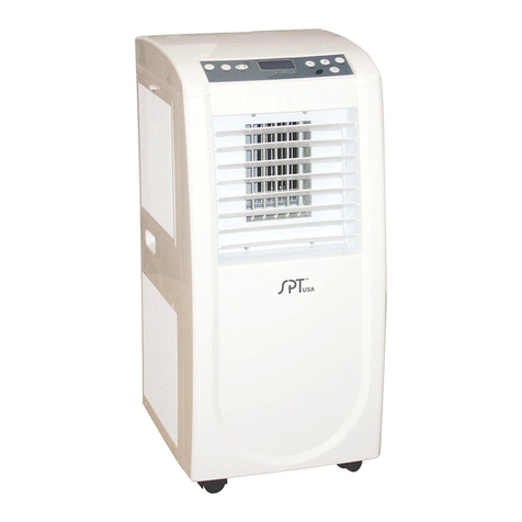
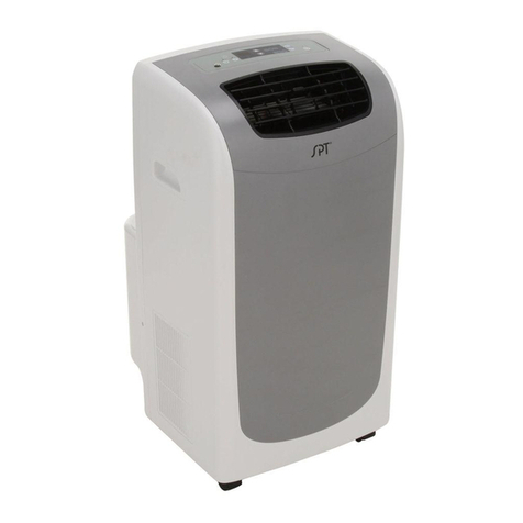
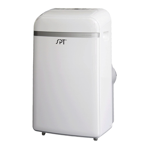
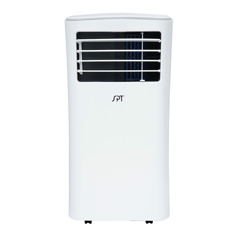
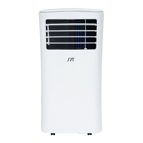
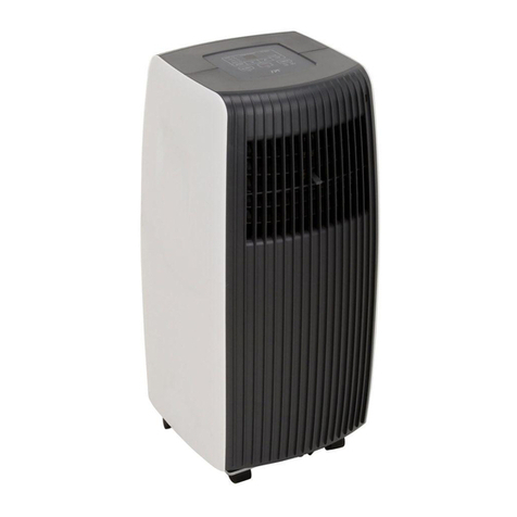
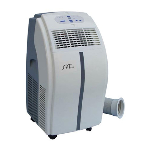
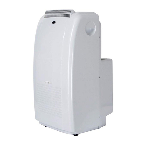
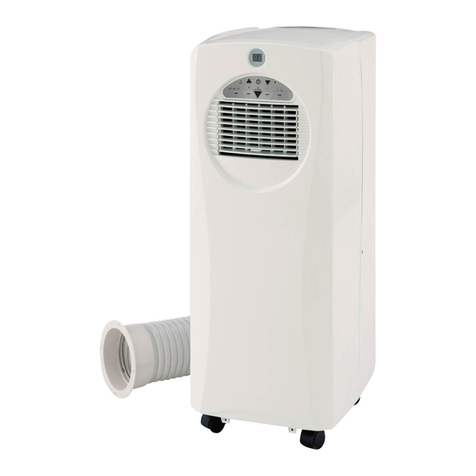
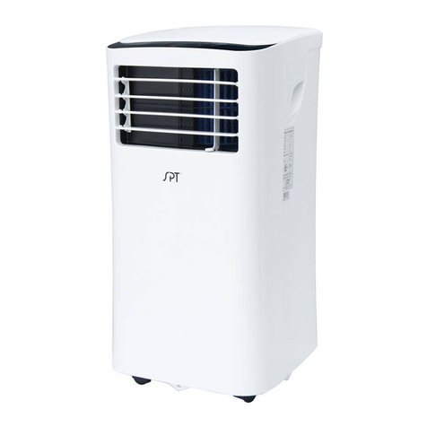
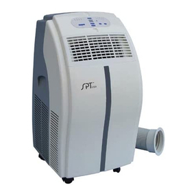
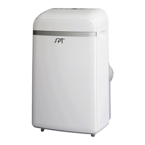
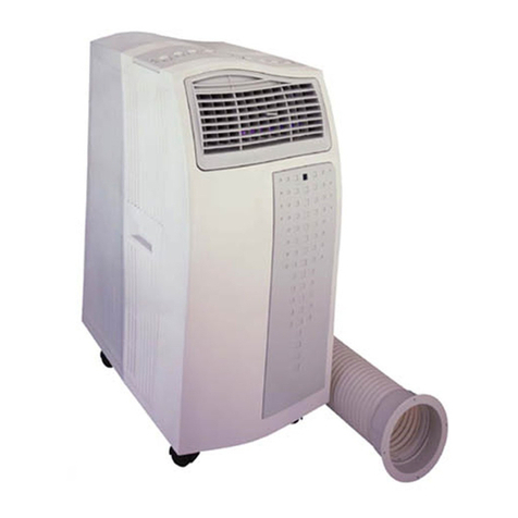
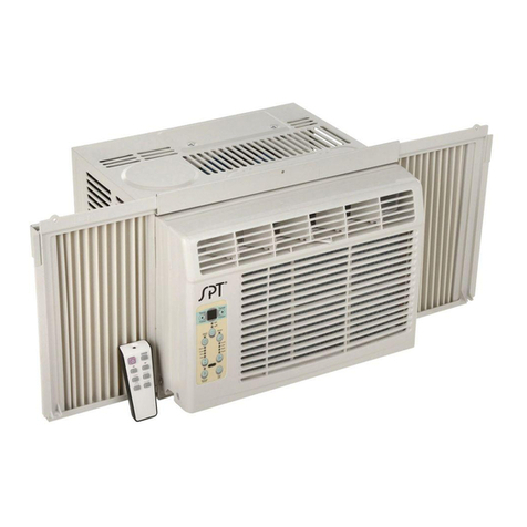
SPT WA-1240AE1 User manual

Thank you for purchasing our Portable Air Conditioner.
Portable Air Conditioner
Instruction Manual
Before using your air conditioner, please read this instruction manual carefully and keep it for future reference.
READ AND SAVE THESE INSTRUCTIONS!
WA-1240AE1: 12,000BTU (cooling only)
WA-1240H1: 12,000BTU (cooling & heating)
WA-1420E1: 14,000BTU (cooling only)
WA-1420H1: 14,000BTU (cooling & heating)

Sociable Remark
Contents
P r e p a r a t i o n
S a f e t y P r e c a u t i o n s
C a u t i o n s
D e s i g n a n d C o m p l i a n c e N o t e
s
I n s t
a
l
l a
t
i o
n
O p e r a t i
o
n
M a i n t e n
a
n
c
e
T r o u b l e S h o o t i n g
B!////////// ))))))))))))))))))))))))))

Preparation
r e a rf r o n t
control panel
handle
(both sides)
horizontal louver
blade
(swing automatically)
Caster power plug socket
power cord buckle
bottom tray
drain outlet
power cord outlet
lower drain outlet
(heating models only)
upper air filter
(behind the grille)
upper air intake
air outlet
lower air filter
lower air intake
upper drain outlet

!!!!(!))!$(5$$675%7%)6785296:6)"5$;<=995>5& &6=& &6$675& &6=65& &=756969895& &5&7%67855& &66595$96"$!65$6956?6@66:%5695A*.;6?6@5(9597=95 9595>665;9

Cautions
5B96=69996>99695?@6=699959656$9:79>566565!65!66:5(6%!!2 %0%!!2 %095$96"5$!656576)95=5966967669Design and Compliance Notes
Design Notice
,QRUGHUWRHQVXUHWKHRSWLPDOSHUIRUPDQFHRIRXUSURGXFWVWKH GHVLJQVSHFL¿FDWLRQV RIWKHXQLWDQGUHPRWHFRQWURODUHVXEMHFWWRFKDQJHZLWKRXWSULRUQRWLFH
Energy Rating Information
The Energy Rating for this unit is based on an installation using an un-extended exhaust duct without adapters A or B (as shown in the Installation section of this manual).

Installation
Choosing The Right Location
Your installation location should meet the following requirements:
-Make sure that you install your unit on an even surface to minimize
noise and vibration.
-The unit must be installed near a grounded plug, and the Collection
Tray Drain (found on the back of the unit) must be accessible.
-The unit should be located at least 30cm (12”) from the nearest wall
to ensure proper air conditioning.
-DO NOT cover the Intakes, Outlets or Remote Signal Receptor of the
unit, as this could cause damage to the unit.
Note About Fluorinated Gasses
-This air-conditioning unit is a hermetically
VHDOHGXQLWWKDWFRQWDLQVÀXRULQDWHGJDVVHV
)RUVSHFL¿FLQIRUPDWLRQRQWKHW\SHRIJDVDQG
the amount, please refer to the relevant label
on the unit itself.
-
S
ervice, maintenance and repair of
this unit must be
SHUIRUPHGE\DFHUWL¿HG
technician.
NOTE:
All the illustrations in the manual are for explanation
purpose only. Your machine may be slightly different.
The actual shape shall prevail.
The unit can be controlled by the unit control panel alone or
with the remote controller.

Installation
Tools Needed
-Medium Philips screwdriver; -Tape measure or ruler; -Knife or scissors;
-Saw (optional, to shorten window adaptor for narrow windows)
Accessories
<RXU:LQGRZ,QVWDOODWLRQ.LW¿WVZLQGRZVFP´DQGFDQ
be shortened for smaller windows.
Part Description
1 pc
1 pc
1 pc
1 pc
1 pc
1 pc
1 pc
1 pc
1 pc
2 pc
2 pc
1 set
1 pc
Unit Adaptor
Window Slider Adaptor
Window Slider A
Window Slider B
Exhaust Hose
Bolt
Foam Seal A (Adhesive)
Foam Seal B (Adhesive)
Foam Seal C (Non-adhesive)
Security Bracket and 2 Screws
Drain Hose
Drain Hose Adaptor
(for
Heating
mode
ls only)
Quantity
R
emote Controller
(
2 AAA batteries, not included)
Window Installation Kit
Step One: Preparing the Exhaust Hose assembly
Press window slider adaptor and unit adaptor onto the exhaust hose.
Clips on the adaptors will automatically clamp onto the exhaust hose.
6WHS7KUHH3UHSDULQJWKH$GMXVWDEOH:LQGRZ6OLGHU
'HSHQGLQJRQWKHVL]HRI\RXUZLQGRZDGMXVWVOLGHUNLWDFFRUGLQJO\,I
WKHZLQGRZUHTXLUHVERWKSLHFHVRIWKHVOLGHUNLWDGMXVWWRQHHGHG
OHQJWKDQGVHFXUHZLWKEROW
Window slider A Window slider B
Bolt
Step Two: Install the Exhaust hose assembly to the Unit
Align the hooks on the unit adaptor to the hole seat of the air outlet
(located on the back of the unit). Insert adaptor and slide hose assembly
downwards into the groove.
Hook Hole Seat
Lower groove
adaptor Make sure the adaptor is inserted into the lower
groove of the air outlet.
2
1
2))
7( 0 3
6
+
2
5
7
&
8
7
7
,
0
(
5
2
1
7
,
0
(
5
2
)
)
0
2
' (
)
$1
6
/
( (
3
6
:
,
1
*
/
( '
Unit adaptor Window slider
adaptor
Exhaust hose Exhaust hose
assembly
!!/!/&")!#A( -$66!& &

Installation
.!8!!F)!!&!(Type 1: Hung Window Installation
Type 2: Sliding Window Installation
966$66)9666$6669$6.6$966$66)966
$6669$6.6$

Installation
.
-$6))6-
(?!6*)B//)++/)/+BB96666@!6G=?6@*6(?@!63=6.=(
=3F
*.
(
=
-& &9=2=?./@=6=$2& -& &&" #H#%!#&!==:

Operation
Swing button
Used to initiate the Auto swing feature.
If auto-swing is in function, press the
button again to stop the louver at
desired angel.
Timer button
Used to initiate the AUTO ON
(
start
time
)
and AUTO OFF
(
stop time
)
SURJUDP
V8VHGLQ
FRQMX
Q
FWLRQZLWK
WKH
DQG
buttons. The
corresponding timer indictor light will
illuminate.
Mode button
Selects the appropriate operating mode. Each
press of
the
button
will select mode in the following sequence:
AUTO, COOL, DRY, FAN and HEAT
(heating models
only).
The
corresponding mode
indicator
will
illuminate
.
8SDQG'RZQEXWWRQV
8VHGWRLQFUHDV
HRU
GHFUHDV
H
WHPSHUDWXUH setting in
1°C/1°F increments
.
Adjustable range:
)
WR)&
WR&
$OVRXVHGWRVHWWLPHUEHWZHHQ
RIaKUV
NOTE: The control is capable of displaying temperature
in Fahrenheit or Celsius. To convert from one to the
other, press and hold the Up and Down buttons
simultaneously
for 3 seconds.
9
Fan button
Control
s
the fan speed. Press to select the
fan speed in four steps
:
LOW, M
E
D, HIGH
and AUTO. The
corresponding fan
speed
indicator
will
illuminate
, except for AUTO
speed. When AUTO is selecyed, all fan
indicators are dark.
Sleep button
Used to initiate the SLEEP function.
Power button
Power switch, turns unit on/off.

Operation 10
LED display
Displays set temperature, in either °C or °F.
Displays auto-timer settings (if any)
When unit is in DRYor FAN modes, displays
currentroom temperature.
Displays error codes and protection codes:
E1: Room temperature sensor error
E2: Evaporator temperature sensor error
E3: Condenser temperature sensor error
E4: Display panel communication error
P1: Bottom tray is full. Connect the drain hose
to drain and empty the bottom tray.
Note: When one of the above malfunction
occurs, turn offthe unit and check for any
obstructions. Restart the unit,if the error
persists, turn off unit and unplug power cord.
Contact Sunpentown customer service at
800-330-0388.
CAUTION! If unit is stopped or powered off unexpectedly,
there will be a 3-minute delay before unit will start up
again. This is to protect the compressor. Unit will
automatically resume after 3 minutes.
Operation Instructions
COOL operation
- Press the MODE button until COOL indicator lights up.
- Press the + or - button to set desired room temperature.
Temperature range is between 62°F~86°F (17°C~30°C).
- Press the FAN button to choose desired fan speed.
HEAT operation ((heating models only)
- Press the MODE button until HEAT indicator lights up.
- Press the + or - button to set desired room temperature.
Temperature range is between 62°F~86°F (17°C~30°C).
- Press the FAN button to choose desired fan speed.
FAN operation
- Press the MODE button until FAN indicator illuminates.
- Press the FAN button to select desired fan speed.
- The temperature cannot be adjusted.
- Exhaust hose connection is not needed.
DRY (dehumidify) operation
- Press the MODE button until the DRYindicator
light illuminates.
- Under this mode, fan speed cannot be selected and
temperature cannot be set. The fan operates at LOW.
- Keep windows and doors closed for the best
dehumidifying effect.
'RQRWFRQQHFWH[KDXVWKRVH¿[WXUHWRZLQGRZ.
AUTO operation
- When the unit is set in AUTO mode, it will automatically
select cooling or fan mode, depending on set temperature
and ambient room temperature.
- The air conditioner will operate in the appropriate mode
based on the set temperature.
- Under AUTO mode, fan speed cannot be set.
Operating Temperature Range
Cool 17-35°C (62-95°F)
Dry
Heat
(heating models only)
13-35°C (55-95°F)
5-30°C (41-86°F)
Mode Temperature Range

Operation
$2(-)$2)
$2&<<6K))$26,66)$2)& 6K)(-)$2)
$2& 6K))$26,66)$2)&<<6K))KD)/,*/M*.366)69996,)& &<<M8//6)(*.+36!)$=66966<68?!($ E@)(69)!($ E)6
9666)<7=!($ E69 &-89!0)$&&06!096*ID.I<+/+/6*ID.I<)%6F! &-9< 1

Operation
Water drainage
Remove the
upper drain plug
¥
¥
¥
Continuous
drain hose
drain hose
adaptor
Continuous
drain hose
Remove the
lower drain plug
delivery lift <1.8m
drain hose
adaptor
drain hose
adaptor X
1)9"
)?,DBuniversal female mender) to
a 3/4" hose (not included,
purchase locally). Connect
to spout. For models without
the drain connector, just
attach drain hose to spout.
- Position the open end
directly over drain area.
#?:@?#@)96)?,DB"
universal female mendor) to a
3/4" hose (not included, purchase
locally). Connect to spout.
- Position the open end directly
over drain area.
- The continuous drain for Heat
mode has a built-in pump,
maximum height for the drain
hose is 5 feet. &-29666666(((6=6B66"P1". At this time,
the compressor will immediately stop but
fan will continue to operate.
- Place a collection pan underneath
the bottom tray drain spout or
carefully move the unit to a drain
location.
- Remove the bottom drain plug and
water will begin to drain out.
- Replace the drain plug and restart
unit. P1 indicator should disappear.

Maintenance
Safety Precautions
-Always unplug the unit before cleaning or servicing.
'2127XVHÀDPPDEOHOLTXLGVRUFKHPLFDOVWRFOHDQWKHXQLW
-DO NOT wash the unit under running water. Doing so causes electrical
danger.
-DO NOT operate the machine if the power cord is damaged. Contact
Sunpentown or a qualified electrician.
Clean the Air Filter
Clean the Unit
Use a lint free cloth soaked with neutral detergent to clean the
housing. Finished by a dry clean cloth.
Storage
-Drain the unit’s water collection tray according to the instructions in
the previous section.
-Run the appliance on FAN mode for 12 hours in a warm room to dry
the interior and prevent mold.
-Turn off the appliance and unplug power source.
&OHDQWKHDLU¿OWHUDFFRUGLQJWRWKHLQVWUXFWLRQVLQWKHSUHYLRXVVHFWLRQ
DQGUHLQVWDOO
-Remove the batteries from the remote control.
Store unit in a cool, dark place. Exposure to direct
sunlight or extreme heat can shorten the life span of the
unit.
Remove the air filter
Maintenance Tips
-The water collection tray should be drained immediately
after P1 error occurs, and before storage to prevent mold.
-In households with animals, you will have to periodically
ZLSHGRZQWKHJULOOWRSUHYHQWEORFNHGDLUÀRZGXHWR
animal hair.
Upper filter
(take out)
Remove the
screw,then
take the lower
filter out.
Clean the filters at least once every two weeks to prevent inferior fan
operation due to dust accumulation.
- Clean filters by washing in
warm water (40°C/104°F)
with a neutral detergent.
- Rinse clean and allow to dry
in a shady area. Do not place
under direct sunlight.

Trouble Shooting
Please check the machine according to the following before asking for maintenance:
Problem Possible Cause
P1 Error Code
In COOL mode: room
temperature is lower than
the set temperature
The air filter is blocked with
dust or animal hair
The unit is low on
refrigerant
Temperature setting is too
high
The windows and doors in
the room are open
The room area is too large
Troubleshooting
Reset the temperature
Unit does not turn
on when pressing
ON/OFF button
Unit does not cool
well
The unit is noisy
and vibrates too
much
The unit makes a
gurgling sound
Exhaust hose is not
connected or is blocked
The Water Collection Tray is full.
Turn off the unit, drain the water
from the Water Collection Tray
and restart the unit.
There are heat sources
inside the room
Turn off the unit and clean the
filter according to instructions
Call a service technician to inspect
the unit and top off refrigerant
Decrease the set temperature
Make sure all windows and doors
are closed
Double-check the cooling area
Turn off the unit, disconnect the
hose, check for blockage and
reconnect the hose
Remove the heat sources if
possible
The ground is not level Place the unit on a flat, level
surface
The air filter is blocked with
dust or animal hair
Turn off the unit and clean the
filter according to instructions
This sound is caused by the
flow of refrigerant inside
the unit
This is normal
66$6(66:6(66>)676

USING THE REMOTE CONTROLLER
Remote Controller Specifications
Battery Required AAA battery x 2 (not included)
Signal Receiving Range
8mOperating temperature -5°C ~ 60°C (23°F ~140°F)
The design and specifications are subject to change without priornotice for product improvement. Consult with the manufacturer for details
NOTE:Buttons design is based on typical model and might be slightly different from the actual one you purchased, the actual shape shall prevail.All the functions described are accomplished by the unit, if the unit is not equipped with a certain feature, there will be no corresponding action. When there are wide differences between Remote controller Illustration and USERS MANUAL on function description, the description on USERS MANUALshall prevail.The device could comply with the local national regulations. In Canada, it should comply with CAN ICES-3(B)/NMB-3(B). In USA, this device complies with part 15 of the FCC Rules. Operation is subject to the following two conditions: (1)This device may not cause harmful interfe-rence, and (2) this device must accept any interference received,including interference that may cause undesired operation.This equipment has been tested and found to comply with the limits for a Class B digital device, pursuant to part 15 of the FCC Rules.These limits are designed to provide reasonable protection against harmful interference in a residential installation.This equipment generates, uses and can radiate radio frequency energy and, if not installed and used in accordance with the instructions, may cause harmful interference to radio communications. However, there is no guarantee that interference will not occur in a particular installation. If this equipment does cause harmful interference to radio or television reception, which can be determined by turning the equipment off and on, the user is encouraged to try to correct the interference by one or more of the following measures:Reorient or relocate the receiving antenna.Increase the separation between the equipment and receiver.Connect the equipment into an outlet on a circuit different from that to which the receiver is connected.Consult the dealer or an experienced radio/TV technician for help.Changes or modifications not approved by the party responsible for compliance could void users authority to operate the equipment.
ON/OFF
SHORT
CUT
TIMER
ON
TIMER
OF F
MODE
FAN
LED
SLEEP SWING
TEMP

Function Buttons
Before you begin using your new air conditioner, make sure to familiarize yourself with the remote control.The following is a brief introduction to the remote control. For detailed instructions on operation of the air conditioner, refer to the Instruction Manual.
SHORT CUTSets and activates your favorite pre-settings. ON/OFFTurns the unit on or off.MODE FAN SPEEDSelects fan speeds in the following order: AUTO LOW
MED HIGHSLEEP Saves energy during sleeping hours.TEMPpIncreases temperature inOO1C(1F) increments.Max. temperature isOO30C(86F) .TEMPqDecreases temperature inOO1C(1F)increments.Min. temperature isOO17C(62F) .TIMER ONSets timer to turn unit on TIMER OFFSets timer to turn unit off SWING Starts and stops louver movement. LEDPress to turn the LED
display on the unit on
or off. ,
ON/OFFTEMP
SHORT CUTTIMER ONTIMER OFFMODEFANLED
.
SLEEPSWING
NOTE: Press and hold and buttons together for 3 seconds will alternate the temperature display OObetween the C & F scale.qpScrolls through modes:AUTO COOL DRY HEAT (heating model only)
FANNOTE: Please do not select
HEAT mode if your model is
cooling only type.

Handling the Remote Controller
NOT SURE WHAT AFUNCTION DOES?
Refer to the
Operation Instructions section
of
this manual for a detailed description o
n
how
to use your air conditioner.
SPECIAL NOTEButton designs on your unit may differ slightly
from the example shown. When there are wide
differences between Remote controller
illustration and USER'S MANUAL on function
description,the description of USER'S MANUAL
shall prevail.
Inserting and Replacing Batteries
The remote controller is powered by two AAA
batteries (not included). The batteries are housed
in the back of the remote, protected by a cover.
Place batteries in the remote control before use.
1. Press down on the cover and slide it outwards
to remove.
2. Insert batteries, paying attention to match the
(+) and (-) ends of the batteries with the symbols
inside the battery compartment.
3. Slide the battery cover back into place.
BATTERY NOTESFor optimum product performance:
Do not mix old and new batteries, or batteries of
different types.
Remove batteries if the remote will not be used for
more than 2 months TIPS FOR USING REMOTE CONTROL
The remote control must be used within 8
meters of the unit.
BATTERY DISPOSALThe unit will beep when remote signal is
received.
Do not dispose of batteries as unsortedCurtains, doors, other barriers and direct
municipal waste. Refer to local laws for sunlight can interfere with the infrared signal
*Fproper disposal of batteries.receiver.

Remote LCD Screen Indicators
Transmission IndicatorLights up when remote sends signal to unitON/OFF displayMODE displayAppears when the unit is turned on, Displays the current and disappears when it is turned offmode, including: AUTO TIMER ON displayTIMER OFF display(Heating models only)
COOLDisplays when TIMER Displays when TIMER ON is setOFF is setDRYHEATFAN Battery display
Low battery detection
SLEEP displayDisplays when SLEEP function is activatedFAN SPEED displayDisplays selected FAN SPEED:HIGH,MED,orLOWThis display is blank whenTemperature/Timer displayset onAUTO speed or DRYDisplays the set temperature by default, or timer setting mode.when using TIMER ON/OFF functionsoOOTemperature range: 17-30C(62F-86F) *BTimer setting range: 0-24 hoursThis display is blank when operating in FAN mode.

How To Use The Basic Functions
The operating temperature range for the unit is 17°C-30°C COOL OPERATION
(62°F-86°F). You can increase or decrease the set temperature 1. Press the MODE button to select COOL
in 1°C(1°F) increments 2. Set your desired temperature using
the Temp Up/Down button.
3. Press the FAN button to select the fan
speed: AUTO, LOW, MED or HIGH.
4. Press the ON/OFF button to start the
AUTO OPERATION
In AUTO mode, the unit will automatically select COOL,
FAN, HEAT (heating models only), or DRY mode based
on the set temperature
1. Press the MODE button to select Auto mode.
2. Set your desired temperature using the
Temp Up/Down button.
3. Press the ON/OFF button to start the unit.
NOTE: FAN SPEED can t be set in Auto mode.
HEAT OPERATION
1. Press the MODE button to
select HEAT .
2. Set desired temperature using the
Temp Up/Down button.
3. Press the FAN button to select the
fan speed: AUTO, LOW, MED,or HIGH.
4. Press the ON/OFF button to start.
NOTE: As outdoor temperature drops,the performance
of your unit's HEATfunction may be affected. In such
instances, it is recommended to use this unit in
conjunction with other heating appliance.
NOTE: Heat mode is for cooling
&
heating models only.
19
1
3
2
ON/OFF
TEMP
SHORT
CUT
TIMER
ON
TIMER
OFF
MODE
FAN
SLEEP LED
SWING
1
3
2
4
ON/OFF
TEMP
SHORT
CUT
TIMER
ON
TIMER
OFF
MODE
FAN
SLEEP LED
SWING
1
3
2
4
ON/OFF
TEMP
SHORT
CUT
TIMER
ON
TIMER
OFF
MODE
FAN
SLEEP LED
SWING
This manual suits for next models
3
Table of contents
Other SPT Air Conditioner manuals
Popular Air Conditioner manuals by other brands

Trane
Trane XL19i-APG02-EN Application guide

REMKO
REMKO MVV 1200 Dc Assembly and operating manual

Bryant
Bryant 707C C Series installation instructions

Fujitsu
Fujitsu Airstage AS A004GTEH Series installation manual

flowair
flowair ELiS C Series Technical documentation operation manual

Soleus Air
Soleus Air GM-CAC-08ESE operating instructions