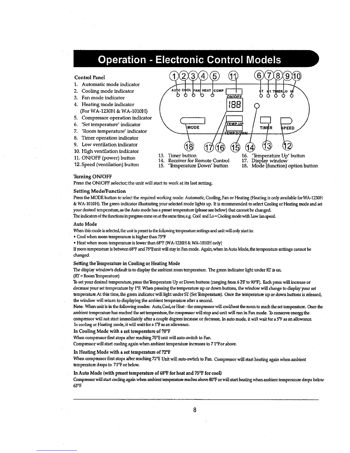
SPT WA-1010E User manual

..... _IWA-iliO!OHi!WA-!Oi!OM i:i :
.......::::!i' ::::
.......:::: :::: ...................... :::': ::,:, :: :
iiimll::: ::: ::::::::::::::::::::::::::::: :::::-::: :: ::::.:''
_i!iii!!_iiiii!i_ili:i
i:i:ii.ii:!i!i!i,ii:ii,ii,i::i ii_i,i i:,i,i!
:::::::::::::::::::::::::::::::::
::::::::::::::::::::::::::::::::::::::
:;.::':::::::: ::::::::::::::::::::::::

THANK "K)U ................................................................................................................................. 1
Energy Saving Tips ........................................................ ........................ i........................... 1
SPECIFICATIONS ................................................................................................................... 2
WA-1010E, WA-1010M and WA-1010H .............................................................. 2
WA-1230E and WA-1230H ................................................................................ 3
BEFORE USE ............................................................................................................................. 4
Accessories ................................................................................................................................... 5
INSTALLATION ............................................................ .......... . ................................................. 6
Mounting the Unit ..................................................................................................................... 6
Mounting the Exhaust Pipe ........................................................................................................ 7
Installation of the Carbon Filter .............................................................................................. 7
OPERATION - ELECTRONIC CONTROL MODELS ................................................................... 8
Control Panel ............................................................................................................. .................8
Turning On/Off. .......................................................................................................................... 8
Setting Mode /Function ............................................................................................................ 8
Auto Mode ................................................................................................................................ 8
Setting the Temperature ....................................................... ....................... ...................... ........ 8
Setting Fan Speed .............................................................................................. ........................ 9
Setting the Timer ................................ _........................ i............................ .......... ....................... 9
• Regulating Airflow Direction ..................................................................................:..............9
OPERATION - MECHANICAL CONTROL MODELS ........................................................... 10
Turning On]Off ........................................................................................................................... 10
Setting Function/Ventilation Speed ......................................................... :......................... 10
Setting the Temperature ......................................................................................................... 11
Setting theTimer ..................................................................................................................... 11
Regulating the Airflow Direction ........................................................................................ 11
DRAINAGE ........................................................................... ......................................................... 12
By the Draining into a Container ....................................................................................... ,12
ByWaterTube (continuous drainage) ................................................................................. 12
MAINTENANCE ..................................................................... .................................................... 13
Cleaning the Housing ...................._........................................................................................ t3
Cleaning the Filter ................................................................................................................. 13
End of Season Storage ............................................ ............................................................ 13
Storing the Power Cord ............................................................... .............................................. 13
_ROUBLESHOOTING ........................................... i.......................................................................... 14
K)UR GUARANTEE ........................................................................................... i.................. i...15

ThankyouforchoosingtheportableairconditionerfromSPTusA,aleading
brandinindoorairtreatment.Wewouldlikeyoutoenjoythemanybenefitsthis
unitoffers,sopleasetakethetimetoreadthismanualcarefullyandtakefull
advantageofthemanyadvancedfeaturesthatyourSPTusaAir Conditioner
offersyou.SPTusahasspecializedin completeindoorenvironmentcontrol,
manufacturingworld-class air conditioners, dehumidifiers and air purifiers
with innovative technology, in designing these advanced products, we have
listened carefully to our customers and have passed their views on to our
research and development laboratories.
We wish you many years of enjoyable use.
After reading this manual, please keep it in a safe place for future reference.
Energy Saving Tips
•Please use the unit in the recommended room size. (Refer to SPECIFICATIONS.),
•Do not locate the air conditioner where fumiture or other objects can obstruct
the airflow.
•Keep blinds/curtains closed during the sunniest part of the day.
• Close the fireplace damper and floor or waU grills so that cool air does not
escape through the chimney or ductwork.
•Keep the filters clean.
Set the unit to maximum cooling and high speed fan initially, then adjust the
unit to a comfortable setting.
NOTE: It is recommended to turn on the air conditioner when the room
temperature is around 75"F. Do not wait until the room is excessively hot.

Model Number WA-1010E
WA'1010 M
Cooling Capacity 10,000BTU/hr
Heating Capacity (1)(2) N/A
Power Consumption 873W /8.15A
Humidity Removal Capacity 50 pts/day
Recommended Room Size* 250 sq. ft.
Power Supply 115V /60Hz /1 Phase
Compressor Rotary
Refrigerant R-22 /18.3 oz
Fan Speed 2
Timer WA-1010E: 1-12hours
WA-101OM: 1-Shours
..... ........ i .......................
Thermostat
Net Weight
WA-1010H
10,000BTU/hr
10,000BTU/hr
873W /8.15A
50 pts.iday
250 sq. ft
115V /60Hz /1 Phase
Rotary
R,22 /18.3 oz
2
1-12 hours
62° F -90°F
62° F - 90°F
63 lbs 66 lbs
.:, ,, : ,
Dimensions 17"W x I7"D x 30"H 17"W x 17"D x 30"H
Working Temperature Cooling: 62OF to ll0°F cooling: 620F £o liOOF.......................................
....................................................... Heatins: 41°F to 81°F
REMARKS:
1. The data may vary, please refer to the rating label on the back on the back of the unit.
2. The above conditions are measured at:
Cooling - Indoor: RT 81°F, RH 60%
Heating - Indoor: RT 68°F, RH 60%
*Uninsulated rooms such as sunrooms, garages, or attics should be less than 250sq. ft.
2

Model Number
Cooling Capacity
Heating Capacity (1)(2)
WA-1230E
12,000BTU/hr
N!A
.............................. ,' ' ' i
Power Consumption 965W /8.5A
Humidity Removal Capacity
Recommended Room Size*
Power Supply
65 pts.tday
400 sq. ft.
115V /60Hz /1 Phase
WA-1230H
12,000BTU/hr
12,000BTU/hr
965W /8.5A
65 pts./day
400 sq; ft.
115V /60Hz /1Phase
Rotary
Refrigerant R-22 /17.3 oz
Fan Speed 2
Timer 1-12hours
Rotary
R-22 /17.3 oz
2
,,,,,,,,,,,,, ,, ,, , ,_,, ,
1-12 hours
62 °F - 90°F
68 lbs.
Thermostat 62°F -90°F
Net Weight 65 lbs.
Dimensions 17"W x 17"D x 30"H 17"W x 17"D x 30"H
Working Temperature Cooling: 62QF to 110°F Cooling: 62°F to t10°F
•Hea_41°Ftoo 81°F
REMARKS:
1. The data may vary, please refer to the rating label on the back on the back of the unit.
2. The above conditions are measured at:
Cooling - Indoor: RT 81°F, RH 60%
Heating - Indoor: RT 68°F, RH 60%
*Uninsulated rooms such as sunrooms, garages, or attics should be less than 400 sq. ft.

Important!
.@
• Transport the unit in an upright position only, or leave it in an upright
position for at least 2 hours before first use.
• Always place the unit on an even surface (Figure 1).
• Make sure the unit is connected to a correctly grounded power supply
(refer to the rating label located at the back of the unit).
• An opening in a window or walt is required to accommodate the
exhaust hose (kit supplied) to expel the warm air.
• Do not cover or obstruct the appliance inlet or outlet grilles (Figure 2)+
• To avoid the risk of shock, the product should never be used in
bathrooms, shower rooms or in any other steamy or wet areas.
• The unit will cool when the room temperature is between 62"F and 110°F
depending on the thermostat setting.
• Do not sit or place objects on the unit:
• Do not touch the unit With wet/damp hands or when standda_gbarefoot.
• Avoid all contact with +chemical based materials.
The filter must be used with the product at all times. When removing for
cleaning, always disconnect the unit from the mains first.
•Turn off the appliance when not in use.
• At the end of each season all water must be drained and the unit and
filters cleaned before storage.
Drainage of the water container is required before moving the unit or
putting it into storage,
If the electric socket is different from the plug provided, have a
professionally qualified electrician replace the plug with a suitable one.
Avoid the use of adaptor plugs, multiple sockets and/or extension leads;
if their use is necessary, ensure that they conform to the current safety
regulations.
Do not pull the supply cable or place it near a source of heat; always
unroll it completely to avoid the possibility Ofdangerous overheating.
If the supply cord is damaged, it must be replaced by the service agent
or a similarly qualified person.
THE MANUFACTURER DISCLAIMS ANY RESPONSIBIIATY IF THE
ABOVE INSTRUCTIONS ARE NOT FOLLOWED.
Fig.t
4

1. Control Panel
2. Cooling Air Outlet
3. Handle
4. Castors
5. Air Filter
6. Air Inlet
7. Exhaust Air Outlet
8. Cord Hanger
9. Water Stopper (Rubber Plug Inside)
Accessories
10.
11.
Adaptor - for insertion over the hose and
into the back of the air conditioner.
Exhaust Hose
Length: 14"-60"
Diameter: 4.75"
12.Plastic slider kit - for filling the open window space,
with circular opening for inserting the hose & round
connector. One set is 3pcs
(forms up to 58.5"L x 6.5W)
1K Round Connector - to be used between
hose m_d window kit or between hose and
wall,
14.
15.
Cap for Round Connector
Remote Control
(Electronic control models only)
5

Mounting the unit
This unit is a portable air conditioner. It can be moved from room to room so that the cooling
can follow you anywhere. Fitting the exhaust hose is easy, through a window or wall.
Please refer to either of the following ways:
1. Using the slider kit /Window (or Sliding Door) installation
The plastic slider kit is composed of 3 sections, length can be adjusted as necessary.
Window
Round
= Remove the 4 screws around the circular opening on the plastic kit.
• Insert the round connector through the circular opening, the lip of the round connector
should be on the flat side of the slider kit. Align the screw openings and replace the 4 screws.
• Determine how many sections of the slider kit your window/sliding door requires,
• Place the slider kit inside the window/door frame, with flat side of round connector facing out.
• To adjust the height of the slider kit: a]ign the small openings on the side, when the
desired height is reached, insert a small screw (not supplied) through one of the opening.
• Extend one end of the exhaust hose and insert it into the Round Connector. Tighten hose
by tuming clockwise.
• Attach the Adapter to the other end of the hose. Tighten by turning Adapter clockwise.
• Attach the Adapter to the back of the unit.
= Slide window /patio door close against the slider kit.
• Make sure tile exhaust hose has no kinks or sharp bends.
• The best distance between the machine and window or wall is 31-39 inches.
2. Using the Through the Wall
Window
• Make ahole (5" in diameter) in the wall to fit the supplied round connector.
•Fit the hose directly to the round conneaor.
• When the hole is not in use, use the cap for the round connector to cover the hole.
6

Mounting the exhaust pipe
• The supplied exhaust hose can be
extended from I foot to 5 feet for
mounting, It is recommended that
you use the shortest possible length
of hose.
* Take care to prevent any kink or
bend in the middle of the exhaust
hose, as this will trap hot exhaust
air, which will radiate back into the
room.
" ,,H,,II""I ¸ II I
WARNING!
The tength of the exhaust pipe is specially
designed according to the specification of this
product.
Do not replace Or extend it with your own hose
as this could cause the unit to malfunction.
Installation of the Carbon Filter
1. Remove the filter frame from the unit.
2. Separate the filter from the filter frame,
3. Remove the active carbon filter from its
plastic bag.
4. Insert the active carbon filter into
1
"f"-[
the filter frame,
5, Fix the filter by reassembling
the fixer onto the filter frame,
6. Re-fit the filter frame inside
the unit.
7, It is recommended to replace
the carbon filter every 3 to 6
months..
-..,,.
7

Control Panel
1. Automatic mode indicator
2. Cooling mode indicator
3. Fan mode indicator
4. Heating mode indicator
(For WA-1230H &WA-10!0H)
5. Compressor operation indicator
6. 'Set tempera_re' indicator
7. "Room temperature' indicator
8. Timer operation indicator
9. Low ventilation indicator
10, High ventilation indicator
11. ON/OFF (power) button
_2.Speed(ventilation)button
13. Timer button 16.
14. Receiver for Remote Control 17.
15. '_mperature Down' button 18.
Turning ON[OFF
Press the ON!OFF selector; the unit will start to work at its last setting,
Setting Mode/Function
Press the MODE button to select the required working mode: Automatic, Cooling, Fan or Heating (Heating is only available forWA-1230H
&WA-1010H), The green indicator illustrating your selected mode lights up. Itis recommended to select Cooling or Heating mode and set
yot_ desired temperature, as the Auto mode has a preset temperature (please see below) that cannot be changed.
Theindicators of the hmdions inpmgress come onat lhesame fime,e.g. Cool and Lo=Cooling mode withLow fanspeed.
Auto Mode
When this mode is selected,the trait is preset to thefollowing temperaturesettings and unitwill only start to:
•o
Cool when room temperature is higher than 75 F
• Heat when room temperature is lower than 68°F (WA-1230H &WA-10!0H only)
tf room temperature is between 68"Fand 75°_unit will stay in Fan mode. Again, when inAuto Mode,the temperature settings cannot be
changed_
Setting theTemperature in Cooling or Heating Mode
The display window's default is to display the ambient room temperature. The green indicator light under RTis or_
_ Room Temperature)
Toset your desired temperature, press theTemperature Up or Down buttons (ranging from 6 _F to 90°F). Each press will increase or
decrease your set temperature by I=E When pressing the temperature up or down buttons, the window will change to display your set
temperature.At this time, the green indicator will light under ST(Set'l_mperatule). Once the temperature up or down buttons is released,
the window will return to displaying the ambient temperature after a second.
Note: When unit is in the following modes: Auto, Cool,or Heat- the compressor will cool/heat the room to much theset temperature. Once the
ambient temperature has reached the set temperature, the compressor will stop and unit will ran in Fan mode, Toconserve energ_ the
compressor will not start immediately after a couple degrees increase or decrease, tn auto mode, it will wait fora 5"Fas an allowance.
In cooling or Heating mode, it will wait fora I"F as art allowance.
In Cooling Mode with a set temperature of 70°F
When compressor first stops after reaching 70°_ unit will auto-switch to Fan.
Compressor will start cooling again when ambient temperature increases to 71*Forabove.
In Healing Mode witha set temperatttre of 72'F
When compressor first stops after reaching 720]_Unit wilt auto-swtich to Fan. Compressor will start heating again when ambient
temperature drops to 71°F orbelow.
In Auto Mode (with preset temperature of 68°F for heat and 75°F for cool)
Compressor will start cooling ag-_ when ambient temperature reaches above 80°F or will start healing when ambient temperature drops below
63°E

Set_ng The Fan Speed
Press the SPEED button to choose the fan speed you require, high or low.
The indicator of high or low fan will light up at the same time.
If the unit is in AUTO mode, it will select the fan speed automatically according to the
ambient temperature (the related indicators, cool, fan or heat will light up), at this time the
fan speed switch is invalid.
Setting the Timer
Press the TIMER button to set the operating hours you desire (1 to 12 hours, the timer
indicator wilt light up). When the set time has elapsed, the machine will turn off
automatically. The display window will show the hour(s) you set as you press the TIMER
button, if the timer button is not pressed, the unit will work continuously.
By pressing tile timer button but without turning on the unit, you
can PRE-SET the time for the machine to work. For example, if you
press the timer to '2', the unit will come on automatically after 2 hours.
All the above functions can also be performed with the supplied remote
control. This remote control requires 2AAA batteries to operate.
Regulating the airflow direction
Turn the roller on the air vent to control the
airflow direction from the vertical louvers.
Notice!
•To prolong the unit's life, it will start 3 minutes after the unit was switched on. After switching
off, please wait at least 3 minutes before switching it on again.
• The cooling system will switch off if the room temperature is lower than set. The fan,
however, keeps working at the set level. If the ambient temperaDare rises above the chosen
temperature +I°F, the cooling will resume.
• In heating mode, the compressor wilt switch off if the room tempera_re is HIGHER than the
set one (Tile fan keeps working at the set level). As the room
temperature drops below the selected level -I°F, the heating will resume.
• This machine is equipped with an ANTI-FROST function. While using the heating function
during low temperatures, sometimes the heating will stop for a while in order to melt the
internal frost. When this occurs just wait for heating to resume.
•As you switch on the heating, the fan will Stop for 15-20 seconds first for warm up purposes.
9

1. Power indicator
2, Fan operating indicator
3. Cooling operating indicator
4. Full water indicator
5. Thermostat
6. Speed switch with options for:
LOW FAN, HIGH FAN, LOW
COOL, HIGH COOL
7. Timer (1-8 hours) as well as
ON/OFF switch
WA-IOIOM
Turning ON/OFF
Set TIMER to ON for continuous operation (the unit will operate as long as it is not
turned off). Power indicator comes on.
To turn off the unit, barn the TIMER to the OFF position.
L
SPEE
Setting Function /Ventilation Speed
WA.1010M
Turn the speed switch to select the required setting:
LOW FAN, HIGH FAN, LOW COOL, HIGH COOL,
SPEED OFF
High Cool
Low Cool High Fan
10

Setting the Temperature
Turn the THERMOSTAT to regulate the temperature you desire: range 62°Fto 90°F.
Setting the Timer
Set the TIMER to the desired operating time (1 to 8hours).
When the set time has elapsed, the machine will shut off automatically.
Regulating the Airflow Direction
Turn the roller on the air vent to control the
airflow direction from the vertical louvers.
NOTICE!
• The compressor will start approximately 3 minutes after the unit is turned
on (this wLtl help prolong the life of the compressor). After switching the
unit off, please wait at least 3 minutes before turning the unit back on.
,The cooling system will switch off if the room temperature is lower than set.
The fan, however, keeps working at the set level, If the ambient temperature
rises above the chosen level, the cooling will resume.
11

During the process of cooling or heating, some water will be extracted from the air into the unit. Most of
this water is used to cool the unit and make it run more efficiently. This is a feature not found in most
Portable Air Conditioners. If the unit is operated in VERYHUMID air, water will collect in the container
inside the unit. If the water container is full, the compressor and fan will stop. The COMP indicator will
blink to inform you to empty the
internal container. To make the cooling function work again, please
empty the water by one of the following methods:
By the Draining into a Container
Use a Shallow Container or Dish
1. Turn off the unit.
2. Position a fiat container or dish under the drain hole.
Do not allow the water to drip continuously into the container, as it
might easily overflow.
3. Remove the drain l_an.ob& rubber plug from the drain hole. The
condensed water will drain out automatically.
4. When the container is almos t full, replace the rubber plug into
the drain hole to stop the water. Empty the container.
5. Repeat steps 2, 3 & 4until all the condensed water is emptied.
6, Once all the condensed water has been removed, replace the
rubber plug into the drain hole firmly. The Fiall Water indicator
should be off now.
7. Replace the drain knob.
* Do not allow the water to drip continuously into the tray, as it
may easily overflow.
By Water Tube (Continuous Drainage)
1. Remove the drain knob and rubber plug and keep them for
future use.
2. Use Teflon tape to cover threading on spout, making aflat
surface for the hose. This will prevent leakage.
3. Connect asuitable water tube (of 3/4" internal diameter -
supplied) to the water hole. The condensed water will drain out
automatically.
4. If you want to extend the water tube you can connect it with
another tube (outside diameter 3A,).
Special Caution for Heating Function!
1. Install the exhaust pipe securely in order to exhaust
the cool air to the outside (please see page 6).
2. You can use the continuous drainage option as described above.
3. The warmer the outside air the more heat will be pumped into
the room. Working range for heat pump function is 41°F to 81°F.
When used in room temperatures outside this range theunit may
not function properly.
4. While using the heating ___nctionduring low temperatures,
sometimes the heating will stop for a while in order to melt the
internal frost. When this occurs, just wait for heating to resume.
This is normal for compressor operated devices.
WaterHole
_/,/ Drain Knob
L_ Drain P[pe
12

Always unplug the unit from the mains before beginning the cleaning.
Cleaning the Housing
Use a soft, damP cloth to wipe the body clean.
Never use strong chemicals, oi!-based products, detergents, chemically treated
cloths or other cleaning solutions. These could possibly damage the cabinet.
Important! Clean the ey&aust air intake area (located on the side, near bottom)
with a vacuum to remove dust accumulation. Excessive dust may cause a
decrease in performance and/or damage to the compressor. Damage caused by
improper maintenance will void the warranty.
Cleaning the Filter
Use a vacuum cleaner or tap the filter lightly to remove loose dust and dirt from the
filters and then rinse them thoroughly under running water (no hotter than 104°F) Do
not wet the activated carbon filter, remove from frame before washing.
Dry thoroughly before replacing.
Notice! Never operate the unit without the filters.
End of Season Storage
Unplug the unit.
Drain the condensed water COMPLETELY (please refer to
page 12). Clean or change the filter.
On a warm day, turn the unit to fan mode for a couple of hours so that the inside can dry out
completely, It is recommended that the unit be put back into its original carton for storage.
Do not stack heavy objects on top of the unit.
i
Storing The Power Cord
When the unit is not in use, please store the power cord away
shown in Figure 3.
Fig.3
t3

The unit doesn't run or
only runs in fan mode • Is the machine plugged in?
• Is the mains power supply on?
• Is the room temperature in the working range?
• Is the unit in auto mode? (Electronic Model)
set to cool or heat and set to proper temperature.
The unit seems to do little • Is there direct sunshine?
(Please c!ose the curtains or blinds)
•Are too many windows or doors open?
•Are there too many people in the room?
• Is there something in the room producing lots of
heat?
The unit seems to do nothing • Is the dust filter dirty?
• Is the air intake or outlet blocked up?
• Is the temperature within the selected tempera_xre +/- 5"F?
• Is the water tar& full? Drain the water.
The room is not coId enough
Too noisy
• The room being cooled should have proper insulation.
If the unit is used in UN-INSULATED
rooms such as Sunrooms, Garages, or Attics, ideal
cooling might not be attained.
-Is the machine positioned unevenly so as to create
vibration?
• Is the floor underneath the machine uneven?
The compressor doesn't run •The overheat protection feature on the compressor
might be on. If this occurs, wait for the
tempera_zre of the unit to drop.
• Is the water container full? Does it need draining?
NEVER TRY TO REPAIR OR DISMANTLE THE UNIT YOURSELF
REPLACEMENT FILTERS:
To purchase Replacement Filters for this unit, contact SPT usa at
1-800-330-0388 and request model number WA-1010 F& WA-1230F.
If this product is defective or not working properly,
please DO NOT return to your retail store.
Please contact us directly for any Service or Technical Assistance at 1-800330-0388.
14

z" "
!:L!i::::i....: : i :: : ::::::_i-_:C_=._i:';:_::: :!:!!::::::-:-:I!:!!I!!I!Z:!II!:!!!I!;!I!:!i!!!!!!Z!!::
; ':;; ':'...' .2' ",' ; ' 'H ............ : .......................................... : ...... ; .............. ;;; ;;..; ;7::;:.':;:,;;;;;;';";;';
..................................................................... ::: ::" ;t.; ':'1::'::.: .................................
Zi.LiZ Z i " . ....... ZZ Z " ::Z:Z_i.:i.i.!Z:Z,!i:!.!!,!!fZ!:Z:Z!k Z!Z!ZiZi.iZii! i.i.ZZ.Zi/ZiiZiiZi, i. iii
................................................ ::,:1': .... : ' - : :'.,' ", ',::"."::':: .... :..... :i"'::::'":'":'

SAFETY POWER SUPPLY CORD:
This Portable Air Conditioner is provided with a Leakage Current Detection
and Interruption circuit (LCDI) built into the plug of the power supply cord.
This device provides protection to reduce the risk of fire due to arcing faults in
the power-supply cord. Each time before using the Portable Air Conditioner,
follow the "Plug Testing Instructions" given below to ensure that the LCDI
circuit is functioning properly.
PLUG TESTING INSTRUCTIONS:
1. PRESS TEST BUTTON. UNIT SHOULD TRIP.
2. PRESS RESET BUTTON FOR USE.
Note: Please do not use this item if above test fails.
The conductors inside this power supply cord are surrounded by shields,
which monitor the leakage current. These shields are not grounded.
Periodically examine the cord for any damage. If the shield gets exposed,
immediately unplug the power supply cord and do not use the Portable Air
Conditioner. Do not repair a damaged cord. Replace the damaged cord with a
new replacement power supply cord or obtain a new replacement power
supply cord by calling Sunpentown Int'l Inc. at 1-800-330-0388.
in the event the LCDI Plug of the power supply cord trips by itself, first
examine the cord for any damage. If there is no damage to the cord then
press the RESET Button. If the LCDI P!ug trips again, then immediately
unplug the power supply cord. Replace the damaged cord with a new
replacement power supply cord or obtain a new replacement power supply
cord by calling Sunpentown Int'l Inc. at 1-800-330-0388.
Do not use The TEST and RESET Buttons as an ON /OFF switch. They are
only meant to periodically check the LCDI plug".
16
Other manuals for WA-1010E
2
This manual suits for next models
4
Table of contents
Other SPT Air Conditioner manuals