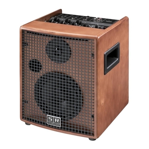
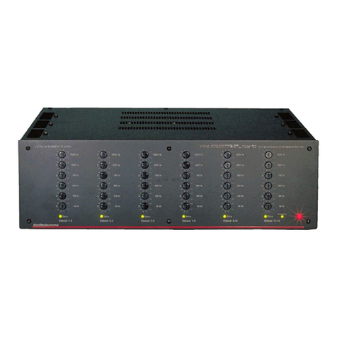
SR Technology PA 8150 User manual

PA 8150 amplifi er
User manual
Manuale d’uso
Finale di potenza multicanale senza compromessi
Multichannel Power Amplifi er without compromise

ATTENZIONE PER RIDURRE IL RISCHIO DI INCENDIO O SHOCK ELETTRICO
NON ESPORRE L’APPARECCHIO ALLA PIOGGIA O ALL’UMIDITA’
WARNING TO RIDUCE THE RISK OF FIRE OR ELECTRIC SHOCK, DO NOT EXPOSE
THIS APPARATUS TO RAIN OR MOISTURE
IMPORTANTI ISTRUZIONI PER LA SICUREZZA
IL SIMBOLO CON UN FULMINE FRECCIA IN UN TRIANGOLO
EQUILATERO AVVERTE L’UTILIZZATORE DELLA PRESENZA
DI UNA PERICOLOSA ALTA TENSIONE, SENZA ISOLAMENTO
ELETTRICO. ALL’INTERNO DELL’APPARECCHIO, LA TEN-
SIONE PUO’ ESSERE SUFFICIENTEMENTE ALTA DA PROVO-
CARE RISCHI DI SHOCK
IL SIMBOLO CON UN PUNTO ESCLAMATIVO IN UN TRIANGO-
LO EQUILATERO AVVERTE L’UTILIZZATORE DELLA PRESEN-
ZA DI IMPORTANTI ISTRUZIONI PER L’USO E LA MANUTEN-
ZIONE DELL’APPARECCHIO
CAUTION
RISK OF ELECTRIC SHOCK
DO NOT OPEN
AVIS: RISQUE DE CHOC ELECTRIQUE, NE PAS OUVRIR
A LIGHTNING WITH ARROW WITHIN AN EQUILATERAL TRI-
ANGLE WARNS THE USER ABOUT THE PRESENCE OF A
DANGEROUS VOLTAGE, WITHOUT ELECTRIC INSULATION,
INSIDE THE DEVICE. THE VOLTAGE COULD BE SUFFICIENT
-
LY HIGH AS TO GENERATE A RISK OF ELECTRIC SHOCK.
THE EXCLAMATION MARK WITHIN AN EQUILATERAL TRI-
ANGLE WARNS THE USER ABOUT THE PRESENCE OF IM-
PORTANT INSTRUCTIONS FOR USE AND MAINTENANCE OF
THE PRODUCT.
IMPORTANT SAFETY INSTRUCTIONS
1
2
3
4
5
6
7
8
9
10
11
12
13
14
Read these instructions
Keep these instructions
Heed all warnings
Follow all instructions
Do not use this apparatus near water
Clean only with dry cloth
Do not block any ventilation openings. Install in accordance with
the manufacturer’s instructions.
Do not install near any heat sources such as radiators, heat register,
stoves, or other apparatus (including amplifiers) that produce heat.
Do not defeat the safety purpose of the polarized or grounding
type plug. A polarized plug has two blades with one wider than
the other. A grounding type plug has two blades and a third
grounding prong. The wide blade or the third prong are provided
for your safety. If the provided plug does not fit into your outlet,
consult an electrician for replacement of the obsolete outlet.
Protect the power cord from being walked on or pinched par-
ticularly at plugs, convenience receptacles, and the point where
they exit from the apparatus.
Only use attachments/accessories specified by the manufacturer.
Use only with the cart, stand, tripod, bracket or table specified
by the manufacturer, or sold with the apparatus. When a cart is
used, use caution when moving the cart/apparatus combination
to avoid injury from tip-over.
Unplug this apparatus during lightning storms or when unused
for long periods of time.
Refer all servicing to qualified service personnel. Servicing is
required when the apparatus has been damaged in any way,
such as power-supply cord or plug is damaged, liquid has been
spilled or objects have fallen into the apparatus, the apparatus
has been exposed to rain or moisture, does not operate nor-
mally, or has been dropped.
Leggere le presenti istruzioni
Conservare le presenti istruzioni
Rispettare tutte le avvertenze
Seguire tutte le istruzioni
Non usare l’apparecchio vicino all’acqua
Pulire l’apparecchio solo con un panno asciutto
Non ostruire nessuna apertura di ventilazione, installare in accordo
con le istruzioni del produttore.
Non installare l’apparecchio vicino a sorgenti di calore come radiatori,
stufe o altri apparati (inclusi ammplificatori) che producono calore.
Non disattivate la protezione di sicurezza di una spina fornita di terra.
Una spina fornita di terra ha due contatti più un terzo contatto per
la terra. Questo terzo contatto è presente per la vostra sicurezza. Se
la spina fornita con l’apparecchio non si adatta alla vostra presa di
corrente, chiamare un elettricista per la sostituzione della presa di
corrente obsoleta
Fate in modo che sia impossibile camminare sul cavo di alimentazione,
evitare che il cavo venga forzato particolarmente all’altezza della spina,
della vaschetta di rete e del punto in cui esso esce dall’apparecchio.
Impiegare solo dispositivi e accessori specificati dal produttore
Usare solo col carrello, asta, treppiedi, sostegno o tavolo specificati
dal costruttore o venduti insieme all’apparecchio. Se si usa un car-
rello, usare cautela nel muovere l’insieme carrello-apparecchio, per
evitare danni alla persona causati dal blocco di una ruota e conseg-
uente rovesciamento del carrello e caduta dell’apparecchio.
Scollegare l’apparecchio dalla rete elettrica durante temporali o in
caso di un lungo periodo di inattività.
Far riferimento al servizio di assistenza tecnica. Richiedere l’intervento
quando l’apparecchio risulta danneggiato e, in ogni caso, quando il
cavo di alimentazione o la presa sono danneggiati, o quando del liquido
è penetrato nell’apparecchio, o l’apparecchio è stato esposto a pioggia
o umidità eccessiva, quando non funziona normalmente o è caduto.

TEMP
1/2
POWER
O
V
E
R
L
O
A
D
B
R
3/4 5/6 7/8
CH
1 2 3 4
5 6 7 8
CH
CH
PA8150
VOL CH 1
5
0 10
5
0 10
5
0 10
5
0 10
5
0 10
5
0 10
5
0 10
5
0 10
VOL CH 2 VOL CH 3 VOL CH 4
VOL CH 5 VOL CH 6 VOL CH 7 VOL CH 8
Interruttore di accensione. In un impianto audio, per evitare
possibili picchi di segnale, è consigliabile accendere gli
amplificatori di potenza per ultimi e spegnerli per primi.
Volumi dei singoli canali. Questi
volumi agiscono ciascuno per il proprio canale solo quando
si è in condizioni di MONO o STEREO.
Led di sovratemperatura. Quando si
accende questo LED, uno o più canali
sono stati esclusi dal funzionamento
per aver raggiunto la massima
temperatura di sicurezza.
Power. Questo LED indica
l’accensione dell’amplificatore.
TEMP
1/2
POWER
O
V
E
R
L
O
A
D
B
R
3/4 5/6 7/8
CH
1 2 3 4
5 6 7 8
CH
CH
PA8150
VOL CH 1
5
0 10
5
0 10
5
0 10
5
0 10
5
0 10
5
0 10
5
0 10
5
0 10
VOL CH 2 VOL CH 3 VOL CH 4
VOL CH 5 VOL CH 6 VOL CH 7 VOL CH 8
ON-OFF switch. In order to avoid possible signal peaks in an
audio installation, it is advisable to switch power amplifiers on last
and to switch them off first.
Volume of each channel. Each of these volumes affects the as-
signed channel only when in MONO or STEREO conditions.
Overheating LED. When this LED
turns on, it means that one or more
channels have been excluded be-
cause maximum safety temperature
has been reached.
Power. This LED indicates that the
amplifier is switched on.
Overload LEDs. When one of these
LEDs turns on occasionally, it means
that the corresponding channel dis-
torts during the peaks of signal.
DESCRIZIONE PANNELLO FRONATALE
1
Questo finale multicanale è stato progettato con componenti di alta
affidabilità ed alta qualità sonora.
Il PA 8150 può erogare una potenza di 8x150 W RMS su 4 ohm, oppure
4x300 W RMS su 8 ohm, ma nella progettazione sono state rese possibili
molte altre modalità di utilizzo, come ad esempio:
1) Installazioni in cui devono essere sonorizzati diversi ambienti
2) Installazioni in cui si vuole realizzare un Dolby Surround di
buona qualità
3) Cinema e teatri
4) Nei Service, dove si devono amplificare diverse linee monitor
E’ stata realizzata anche un’accensione SOFT START perché in alcuni
ambienti lo spunto di accensione può causare dei problemi all’impianto
elettrico.
This multichannel amplifier has been designed with highly reliable and
excellent sound quality components.
The 8150 PA can supply a power of either 8x150 W RMS on 4 ohm, or
4x300 W RMS on 8 ohm. However, it has also been designed for use in
many other ways. For example:
1) Installations with different kinds of environments that need to be
covered.
2) Installations where a quality Dolby Surround system is desired.
3) Cinemas and theatres
4) Services that need to amplify different monitor lines
A SOFT START at switch-on has also been implemented, due to the fact
that in certain environments the switch-on transient can cause problems
with the electric system.
DESCRIPTIONDESCRIZIONE
FRONT PANEL DESCRIPTION
2 3 4 5 6 7 8 9
10
11
Bridge canale 3/4 Quando si accende questo LED,
vuol dire che il canale formato dai due canali 3 e 4 sta
funzionando A PONTE.
LEDs di overload. Se uno di questi
LEDs si accende saltuariamente
significa che il canale corrispondente
entra in distorsione nei picchi di
segnale.
12 13 14 15 16 17 18 19
20 Bridge canale 1/2 Quando si accende questo LED,
vuol dire che il canale formato dai due canali 1 e 2 sta
funzionando A PONTE.
21
Bridge canale 5/6 Quando si accende questo LED,
vuol dire che il canale formato dai due canali 5 e 6 sta
funzionando A PONTE.
Bridge canale 7/8 Quando si accende questo LED, vuol
dire che che il canale formato dai due canali 7 e 8 sta
funzionando A PONTE.
22
23
12 3 4 5
6 7 8 9
10 11
12
13
15
14
16
17
18
19
20 21 22 23
Bridge channels 1/2. When this LED turns on it indicates that
the channel made up by channels 1 and 2 is working in BRIDGE
connection.
Bridge channels 3/4. When this LED turns on it indicates that
the channel made up by channels 3 and 4 is working in BRIDGE
connection.
Bridge channels 5/6. When this LED turns on it indicates that
the channel made up by channels 5 and 6 is working in BRIDGE
connection.
Bridge channels 7/8. When this LED turns on it indicates that
the channel made up by channels 7 and 8 is working in BRIDGE
connection.
Se il LED si accende con luce fissa la distorsione è continua
ed è possibile che intervenga il circuito di protezione che
disconnette per qualche secondo l’uscita del relativo canale.
If the LED stays on and does not flash, distortion is continuous
and it is possible that the protection circuit comes into action,
disconnecting the output of the corresponding channel.

BRIDGE
OUT 8 OUT 7 OUT 6 OUT 5
BRIDGEST/M
4 3 2 1
ST/M
5678
BRIDGE BRIDGE
ST/M
I
N
P
U
T
S
STEREO
MONO
OUT 4 OUT 3 OUT 2 OUT 1
CAUTION
RISK OF ELECTRIC SHOCK
DO NOT OPEN
ATTENTION RISK DE CHOC ELECTRIQUE. NE PAS OUVRIR
60 Hz 100 - 120V
50 Hz 220 - 240V
Made in Italy
Quando uno di questi pulsanti (25-26-27) viene azionato, le rispettive
uscite ripetono le uscite del canale 1 (uscita 40) e del canale 2 (uscita
41), ma con controlli indipendenti di volume.
I segnali audio applicati agli ingressi 3 e 4 vengono esclusi se si preme
il pulsante 25, e lo stesso accade per i segnali applicati agli ingressi 5
e 6 se si preme il pulsante 26 e per i segnali applicati
agli ingressi 7 ed 8 se si preme il pulsante 27.
Invece non vengono mai esclusi i segnali applicati agli ingressi 1 e 2,
anche se si preme il pulsante 24.
Nelle installazioni col PA 8150, usando i pulsanti 24.25.26-27 si
possono realizzare moltissime utili configurazioni. Per esempio:
a) Se si hanno alcuni locali (massimo 4) forniti ciascuno di due
casse acustiche (per poter ottenere l’effetto stereo), e si
vuole riprodurre in questi locali lo stesso programma stereo
basta lasciare il pulsante 24 in posizione stereo e premere
il pulsante 25 per poter avere lo stesso programma stereo
sulle uscite 42 e 43, il pulsante 26 per averlo sulle uscite 44
e 45, e il pulsante 27 per averlo sulle uscite 46 e 47.
b) Se invece si hanno alcuni locali (massimo 8) forniti ciascuno
di una sola cassa acustica, e si vuole riprodurre in questi
locali lo stesso programma mono, basta posizionare il
pulsante 24 su mono e premere il pulsante 25 per poter
Questi connettori Canon sono ingressi bilanciati elettro-
nicamente e presentano una impedenza di 22 kOhm. Essi
corrispondono ai canali 1-2-3-4-5-6-7-8.
Quando i pulsanti sono in posizione stereo ad ogni ingresso
corrisponde la sua uscita ed il suo volume.
Stereo-mono canali 5/6 e canali 7/8.
Stesse considerazioni fatte per il pulsante 25.
avere lo stesso programma mono sulle uscite 42 e 43, il
pulsante 26 per averlo sulle uscite 44 e 45, e il pulsante 27
per averlo sulle uscite 46 e 47.
Importante notare che, sia nel caso a) che nel caso b), i volumi relativi
alle otto uscite restano sempre controllabili in modo individuale.
Bridge canali 1/2 . Premendo questo pulsante, i canali 1 e 2
(ingressi 32 e 33) vengono connessi a ponte (bridge). In queste
condizioni il volume attivo è quello del canale 1 (comando 2) e le
uscite da collegare sono il morsetto positivo dell’uscita canale 1
(40) e il morsetto positivo dell’uscita canale 2 (41). Se il pulsante
24 è in posizione stereo, allora solo il canale 1 (ingresso 32)
verrà amplificato in bridge, in caso contrario verrà amplificata in
bridge la somma dei segnali presenti sugli ingressi canale 1 e 2
(ingressi 32 e 33).
Bridge canali 7/8. Premendo questo pulsante, i canali 7 e 8
(ingressi 38 e 39) vengono connessi a ponte (bridge). In queste
condizioni il volume attivo è quello del canale 7 (comando 8) e
le uscite da collegare sono il morsetto positivo dell’uscita canale
7 (46) e il morsetto positivo dell’uscita canale 8 (47). Questo
avviene se il pulsante 25 non è attivato, e in queste condizioni
il segnale che viene amplificato in bridge è quello del canale 7
(ingresso 38).
Se il pulsante 27 è attivato, allora verrà amplificato in bridge il
canale 1 (ingresso 32) se il pulsante 24 è in posizione stereo e in
caso contrario verrà amplificata in bridge la somma dei segnali
presenti sugli ingressi canale 1 e 2 (ingressi 32 e 33).
DESCRIZIONE PANNELLO POSTERIORE
43 42 41 40
47 46 45 44
29 25 28 24
31 27 30 26
35 34 33 32
39 38 37 36
32 33 34 35 36 37 83 39
40 41 42 43 44 45 46 47
Sono le otto uscite di potenza a morsettiera. Sul pannello
sono stampate le indicazioni che definiscono la polarità dei
morsetti e i canali di riferimento.
24 Stereo-mono. Pulsante che mette in mono i canali 1 e 2
(connettori d’ingresso 32 e 33).
In posizione mono, i segnali d’ingresso che vengono applicati
ai connettori 32 e 33 vengono sommati e fatti uscire IN MONO
sulle uscite 40 e 41. Sono attivi i rispettivi volumi 2 e 3.
25 Stereo-mono canali 3/4. Se il pulsante 24 è in posizione
stereo e si aziona il pulsante 25, l’uscita 42 ripete l’uscita 40 e
l’uscita 43 ripete l’uscita 41, ma i controlli di volume (2-3-4-5)
restano indipendenti.
Se il pulsante 24 è in posizione mono e si aziona il pulsante
25, dalle uscite 40-41-42-43 verrà fuori il segnale mono
ottenuto per somma dei due segnali applicati agli ingressi 32
e 33; i controlli di volume (2-3-4-5) restano indipendenti
26 27
28
29
Bridge canali 3/4. Premendo questo pulsante, i canali 3 e 4 (ingressi
34 e 35) vengono conness a ponte (bridge). In queste condizioni
il volume attivo è quello del canale 3 (comando 4) e le uscite da
collegare sono il morsetto positivo dell’uscita canale 3 (42) e il
morsetto positivo dell’uscita canale 4 (43). Questo avviene se il
pulsante 25 non è attivato, e in queste condizioni il segnale che
viene amplificato in bridge è quello del canale 3 (ingresso 34). Se
il pulsante 25 è attivato, allora verrà amplificato in bridge il canale
1 (ingresso 32) se il pulsante 24 è in posizione stereo e in caso
contrario verrà amplificata in bridge la somma dei segnali presenti
sugli ingressi canale 1 e 2 (ingressi 32 e 33).
30
Bridge canali 5/6. Premendo questo pulsante, i canali 5 e 6
(ingressi 36 e 37) vengono connessi a ponte (bridge). In queste
condizioni il volume attivo è quello del canale 5 (comando 6) e
le uscite da collegare sono il morsetto positivo dell’uscita canale
5 (44) e il morsetto positivo dell’uscita canale 6 (45). Questo
avviene se il pulsante 25 non è attivato, e in queste condizioni
il segnale che viene amplificato in bridge è quello del canale 5
(ingresso 36).
Se il pulsante 26 attivato, allora verrà amplificato in bridge il
canale 1 (ingresso 32) se il pulsante 24 è in posizione stereo e in
caso contrario verrà amplificata in bridge la somma dei segnali
presenti sugli ingressi canale 1 e 2 (ingressi 32 e 33).
31

BRIDGE
OUT 8 OUT 7 OUT 6 OUT 5
BRIDGEST/M
4 3 2 1
ST/M
5678
BRIDGE BRIDGE
ST/M
I
N
P
U
T
S
STEREO
MONO
OUT 4 OUT 3 OUT 2 OUT 1
CAUTION
RISK OF ELECTRIC SHOCK
DO NOT OPEN
ATTENTION RISK DE CHOC ELECTRIQUE. NE PAS OUVRIR
60 Hz 100 - 120V
50 Hz 220 - 240V
Made in Italy
Therefore, when one of these buttons (25-26-27) is activated, the
respective outputs repeat the output of channel 1 (output 40) and
channel 2 (output 41), but with independent control volumes.
If button 25 is pressed the applied audio signals at inputs 3 and 4
(34 – 35) are excluded, and the same happens for signals applied
at inputs 5 and 6 (36 – 37) if you press button 26. Signals applied
at inputs 7 and 8 (38 – 39) are excluded if you press button 27.
Signals applied at inputs 1 and 2 are never excluded, even if but-
ton 24 is pressed.
Installations with the PA 8150 can realise many useful configura-
tions by using buttons 24.25.26-27. For example:
a)
If there is a number of rooms (maximum 4), each one
supplied with two acoustic boxes (in order to obtain the
stereo effect) and the same stereo program needs to be
applied to these rooms, then all that is needed is to leave
button 24 in stereo, then press button 25 in order to have
the same program at outputs 42 and 43, button 26 for
outputs 44 and 45, and finally button 26 for outputs 46
and 47.
b) If however there is a number of rooms (maximum of 8)
each room with one acoustic box, and the same mono
program needs to be reproduced, then all that is required
These XLR connectors are electronically balanced inputs and
present an impedance of 22 kOhm. They correspond to chan-
nels 1-2-3-4-5-6-7-8. When the buttons (24-25-26-27) are in
stereo position, for each input there is a corresponding output
and a corresponding volume.
Stereo-mono channels 5/6 and channels 7/8, the
same applies as with 25.
is to place button 24 on mono, then press button 25 to
have the same program at outputs 42 and 43, button 26 for
outputs 44 and 45, and button 26 for outputs 46 and 47.
It is important to note that for both the above cases, the volumes
relative to the eight outputs are still controlled individually.
Bridge channels 1/2. Pressing this button applies a bridge
connection to channels 1 and 2 (inputs 32 and 33). Under this
condition the active volume is the channel 1 volume (control
2) and the outputs to be connected are the positive terminal
of channel 1 output (40) and the positive terminal of channel
2 output (41). If button 24 is in stereo, then only the signal
present at channel 1 input (32) will be amplified in bridge. If
not, then the sum of the signals present at channel 1 and 2
inputs (32 and 33) will be amplified in bridge.
Bridge channels 7/8. Pressing this button applies a bridge
connection to channels 7 and 8 (inputs 38 and 39). Under
this condition the active volume is the channel 7 volune
(control 8) and the outputs to be connected are the positive
terminal of channel 7 output (46) and the positive terminal
of channel 8 output (47). This will occur if button 27 is not
active and in these conditions the signal amplified in bridge
is the one from channel 7 (input 38). If button 27 is activated
then channel 1 (input 32) will be amplified in bridge but only
if button 24 is in stereo and if not, then the sum of signals
present at channel 1 and 2 inputs (32 and 33) will be ampli-
fied in bridge.
BACK PANEL DESCRIPTION
43 42 41 40
47 46 45 44
29 25 28 24
31 27 30 26
35 34 33 32
39 38 37 36
32 33 34 35 36 37 83 39
40 41 42 43 44 45 46 47
These are the 8 power outputs with terminal board. The in-
dications that define the terminal polarity and the reference
channels are marked on the panel.
24 Stereo-mono. Button that puts channels 1 and 2 in mono (in-
put connectors 32 and 33).
In mono, the input signals applied to connectors 32 and 33
are added together, amplified and made available IN MONO
at outputs 40 and 41. Volumes 2 and 3 are active.
25 Stereo-mono channels 3/4. If button 24 is in stereo and but-
ton 25 is activated, output 42 repeats output 40 and output
43 repeats output 41, but volume controls (2-3-4-5) remain
independent.
If button 24 is in mono and button 25 is activated, the mono
signal obtained by summing together the two signals applied
at inputs 32 and 33 will come from outputs 40-41-42-43, but
volume controls (2-3-4-5) remain independent.
26 27
28
29 Bridge channels 3/4. Pressing this button applies a bridge
connection to channels 3 and 4 (inputs 34 and 35). Under this
condition the active volume is the channel 3 volume (control
4) and the outputs to be connected are the positive terminal
of channel 3 output (42) and the positive terminal of channel
4 output (43). This will occur if button 25 is not active and in
these conditions the signal amplified in bridge is the one from
channel 3 (input 34). If button 25 is activated then channel 1
(input 32) will be amplified in bridge but only if button 24 is in
stereo and if not, then the sum of signals present at channel
1 and 2 inputs (32 and 33) will be amplified in bridge.
30 Bridge channels 5/6. Pressing this button applies a bridge
connection to channels 5 and 6 (inputs 36 and 37). Under this
condition the active volume is the channel 5 volume (control
6) and the outputs to be connected are the positive terminal
of channel 5 output (44) and the positive terminal of channel
6 output (45). This will occur if button 26 is not active and in
these conditions the signal amplified in bridge is the one from
channel 5 (input 36). If button 26 is activated then channel 1
(input 32) will be amplified in bridge but only if button 24 is in
stereo and if not, then the sum of signals present at channel
1 and 2 inputs (32 and 33) will be amplified in bridge.
31

Rel.311208
Potenza d’uscita continua
150 W RMS su 4 ohm per ogni canale
tutti i canali max volume distorsione a 1KHz 0,02% THD
Potenza d’uscita continua
300 W RMS su 8 ohm per ogni canale
tutti i canali a ponte, max volume
distorsione a 1KHz 0,02% THD
Potenza d’uscita di picco 260 W picco su 4 ohm
tutti i canali max volume
Potenza d’uscita di picco 520 W picco su 8 ohm
tutti i canali a ponte, max volume
Sensibilità d’ingresso 2 V efficaci
Impedenza d’ingresso 22 kOhm
Ingressi bilanciati XLR bilanciati
Slew rate 40 V/µs
Rapporto segnale/rumore, per canale
-105 db, curva non pesata
Risposta in frequenza 20 Hz – 20 KHz ± 0,2 db
Potenza max assorbita 1300 VA
Tensione di alimentazione 230 Vac
Raffreddamento Due ventole radiali
Protezioni Sovraccarico – DC termica
cortocircuito in uscita
Dimensioni 400x88x430 mm
Peso 16 kg
Continuous output power 150 W RMS on 4 ohm per channel
all channels at max volume distortion at 1KHz 0.02% THD
Continuous output power 300 W RMS on 8 ohm per channel
all bridged channels at max volume distortion at 1KHz 0.02% THD
Peak output power 260 W peak on 4 ohm
all channels at max volume
Peak output power 520 W peak on 8 ohm
all bridged channels at max volume
Input sensitivity 2 V RMS
Input impedance 22 kOhm
Balanced inputs XLR balanced
Slew rate 40 V/µs
Signal to noise ratio per channe -105 db, unweighted curve
Frequency response 20 Hz ÷ 20 KHz ± 0.2 db
Max power consumption 1300 VA
Power supply voltage 230 Vac
Cooling Two radial fans
Protections Overload - output DC
Thermic shut down - short circuit
Dimensions 400x88x430 mm
Weight 16 kg
Read carefully this manual and follow these
precautions before operating the device
WARNING
SR TECHNOLOGY s.r.l. Via Ceccaroni 1 - 62019 Recanati (MC) Italy
www.sr-technology.com
Tel: +39 071 757 37 20 - Fax: +39 071 757 72 50
CARATTERISTICHE TECNICHE TECHNICAL SPECIFICATIONS
Leggere attentamente il presente manuale e seguire
le avvertenze prima di utilizzare l’apparecchio
AVVERTENZE
• Keep this manual for possible future needs.
• Pay attention not to pour liquids onto the device and do not operate in a
condition of excessive humidity.
• Do not install the device close to sources of excessive heat, do not expose
it to direct solar radiation and do not position it without protection in a dusty
environment.
• Be sure that the mains voltage doesn’t exceed the value indicated in the
back panel.
• Do not use the device if the mains cable or the plug aren’t in a perfect condi-
tion (if necessary,replace it).
• If the mains cable has to be replaced, the operation must be carried out by
qualified personnel. Replace the cable exclusively with one that is an exact
substitute.
• In order to avoid induced disturbances, do not install the device close to
power transformers, TV sets, RF trasmitters, electric motors or any source of
electric energy.
• Avoid to point microphones against loudspeakers: this could generate an-
noying whistles (Larsen effect) that could damage them.
• In order to avoid unpleasant and costly inconveniences, use only original
connecting cables.
• To complete disconnect this apparatus from the AC mains, disconnect the
power supply cord plug from the AC receptable
• Do not use, for cleaning, any solvent like acetone or alcol. These could dam-
age the external finishing and the serigraphy of the panels.
• In case of malfunction of any part of the system, call the nearest SR technical
assistence centre or a specialized technical centre. Avoid to try personal repair.
• In order to obtain a suitable ventilation, the device heat sink should never be
covered or obstructed by blankets, sofas or similar forniture. Be sure also to
leave sufficient clearance between the heat sink and any other surface.
• No source of free flame , like lighted candles, should be placed on the device.
• The device should not be exposed to dripping, drops or sprinkling of water.
No object containing liquids should be placed on the device.
• The device should be connected to a mains socket outlet having a good con-
nection to the protection ground system.
• When the device is installed, be sure that the mains socket and the plug of
the mains cable are easily accessible.
• Conservare questo manuale per usi futuri.
• Prestare attenzione a non versare liquidii nell’apparecchio e non uti-
lizzare in condizioni di eccessiva umidità.
• Non installare l’apparecchio vicino a forti sorgenti di calore e alle
radiazioni dirette del sole e in ambienti polverosi.
• Assicurarsi che la tensione di rete non superi i valori indicati nella
parte posteriore dell’apparecchio.
• Non utilizzare l’apparecchio se il cavo di alimentazione non si pre-
senta in perfette condizioni (se necessario sostituirlo).
• In caso di sostituzione del cavo di alimentazione: l’operazione deve
essere compiuta da personale qualificato.
Il cavo deve essere sostituito con uno perfettamente equivalente.
• Per evitare disturbi indotti non installare l’apparecchio in prossimità
di trasformatori, televisori, trasmettitori RF, motori elettrici e altre sor-
genti di energia elettrica.
• Evitare di puntare i microfoni verso gli altoparlanti: questo può gener-
are noiosi fischi (effetto Larsen) che può danneggiarli.
• Per evitare spiacevoli e costosi inconvenienti, utilizzare solo cavi originali.
• Per disconnettere l’apparecchio dalla rete elettrica occorre scolle-
gare il cavo dalla presa di rete.
• Per la pulizia non utilizzare solventi o alcool. Questi possono dan-
neggiare le verniciature e le serigrafie.
• In caso di malfunzionamento di qualunque parte del sistema, chia-
mare il più vicino centro di assistenza SR o un centro specializzato e
autorizzato. Evitare di affidare l’apparecchio a riparatori generici.
• Per ottenere una sufficiente ventilazione, il dissipatore di calore non
deve essere mai coperto da panni o mobili. Assicurarsi di lasciare
spazio fra i dissipatori di calore e altre superfici.
• Non utilizzare fiamme libere come accendini, candele o altro vicino
all’apparecchio.
• L’unità non deve essre esposta a gocciolamento o spruzzi di acqua.
Non posizionare oggetti contenenti liquidi sull’apparecchio.
• L’unità deve essere collegata ad una presa di corrente munita di ef-
ficiente presa di terra.
• Una volta installato l’apparecchio accertarsi che la presa e la spina
dell’alimentazione siano facilmente accessibili.
Table of contents
Other SR Technology Amplifier manuals
Popular Amplifier manuals by other brands

Eton
Eton USA PA 504 Installation & operation

Audio Control
Audio Control EQT Concert Series Owner/installer instruction manual

Audiopole
Audiopole CLIMAX 1002 user manual

JB Systems Light
JB Systems Light PC8 Mk2 Operation manual

BLACK STAR
BLACK STAR HT Club 40 owner's manual
BASSFACE
BASSFACE DB1.1 instruction manual
IMG STAGE LINE
IMG STAGE LINE STA-300 instruction manual

PowerAcoustik
PowerAcoustik 4DS-400 Introduction manual

WorkPro
WorkPro HomeAmp user manual

Sunfire
Sunfire Cinema Grand 200-seven user manual

Eton
Eton ECC 1200.1 Installation & operation guide
IMG STAGE LINE
IMG STAGE LINE STA-1603 CLUB instruction manual
