SR X250 User manual

X250tm Assembly Instructions, Page 1
Introduction
You are in for a real treat. You’re going to find that your new
X250 is one of the fastest building and best flying aircraft you’ve ever
owned. Nothing has been taken for granted. If you follow our
instructions, you’ll be amazed at how fast you’ll have your X250 in
the air.
We’ve photographed just about every step in completing the
X250. The notes that accompany each photograph will give you a
“heads up” about any tricks or possible problems you could run into
while completing that particularstep. Please read the instructions!
We used thin, fast setting, CA glue in assembling all of the X250
prototypes. If we recommend a different glue for a particular step,
we’ll mention it in the notes.
Although any small radio system can be used, we’ve specifically
set up the X250 for the very popular Hitec HS-60 servos and the
Hitec “555” or “Super Slim” Series sub micro receivers. These servos
and receivers will work with any brand of transmitter and we strongly
recommend them. If you can’t find them locally, we always keep
them in stock at SR.
Finally, you’ll find that a 5/64” Ball Driver and a Higley
Trimmer will really speed things up. Both are available from SR if
you don’t already have them.
On the following page you’ll find detailed technical
specifications and power system recommendations.
X250tm Assembly Instructions©1999
Preparing the parts...
We’ve included a master parts sheet that identifies each part in
the kit and tells you where the part is located. We’ve deliberately left
all of the MicroLaser Cut parts for the X250 in their sheets to protect
them. Use your modeler’s knife and a straight edge to finish the cuts
and release the parts. Just about all of the cuts will be with the grain
to make it easier for you. You can either cut out all of the parts before
you begin or leave them in their sheets until you’re ready for them.
It’s up to you, but you’ll be less likely to lose a part if you leave it in
its sheet until you’re ready for it.
In most cases, the SR MicroLaser Cut process leaves the balsa
parts with a honey colored edge that needs no sanding. Unfortunately,
the glues used in making plywood tend to glaze the edges of the
plywood parts when they are laser cut. We use a special plywood that
is designed for laser cutting, but we recommend that all plywood
parts be lightly sanded along their edges before gluing the part in
place. In addition, like spruce, plywood parts tend to have an oily film
on their surfaces which prevents CA glues from taking a good hold.
For this reason, we recommend that all plywood parts be given a light
sanding on all surfaces before youglue them in place.
X250tm Assembly Instructions, Page 2
Technical Specifications...
In spite of the X250’s small size, it’s probably one of the
most carefully designed model aircraft ever kitted. Literally
hundreds of hours of computer time were spent optimizing the
design. Rather than just designing an aircraft, we designed an
entire system. There’s no point in designing an aircraft that
requires a motor, gear ratio, battery, or prop that doesn’t exist.
Instead we evaluated dozens of combinations of components
to come up with the optimum, complete system.
We know that some of you will be tempted to change
some of the components in the power system. We suggest that
you don’t. Our target was an aerobatic aircraft that would
easily do consecutive loops yet still give you 7 to 9 minutes of
aerobatic flight and 12 to 15 minutes of sport flying. The
X250 fulfills this goal. If you change any of the components,
you may gain a small advantage in one area of performance,
but you’ll definitely be losing performance in another area.
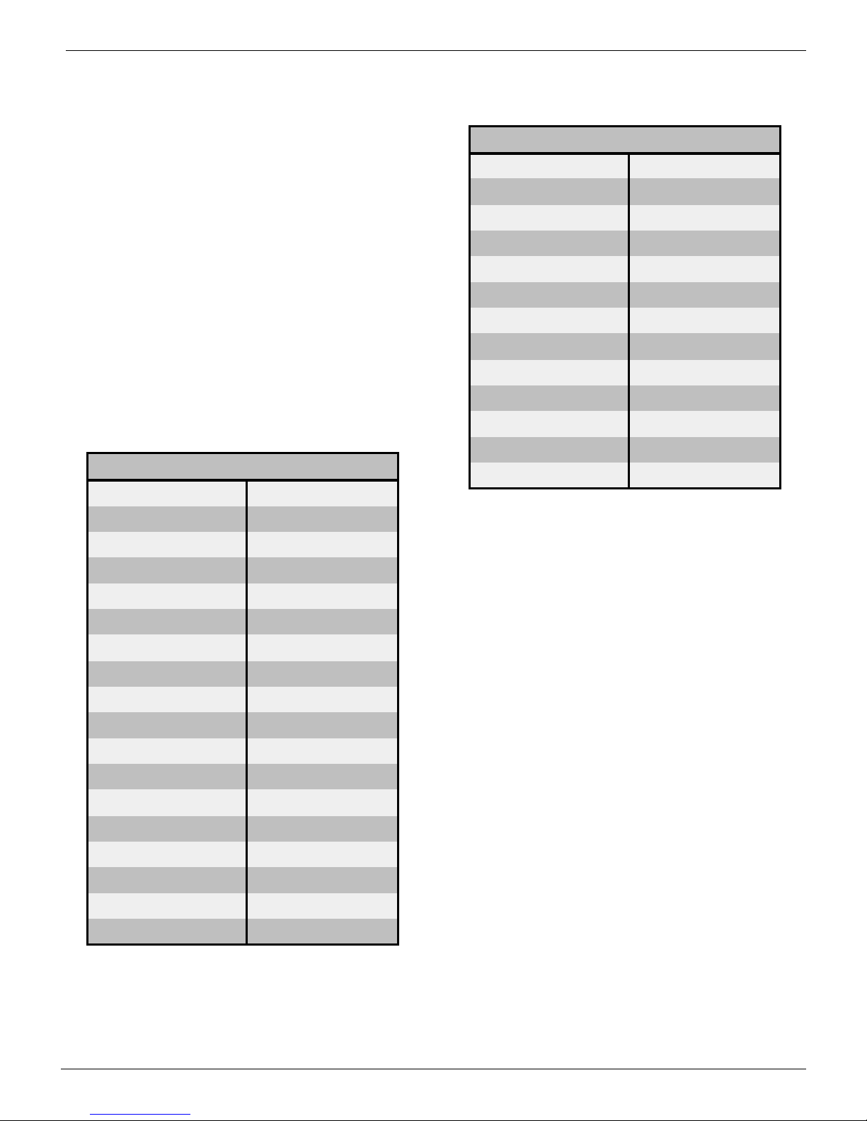
Here is our definition of Optimum Performance:
The following table lists the specific equipment we’ve
evaluated and tested to yield the above performance data. You
Aircraft SR X250 (aileron version)
Wing area 266 square inches
WingSpan 36”
Aspect Ratio 4.3:1
CG Limits 2” to 2.75”
Airfoil Computer Optimized by SR
Typical Wt. w/ 10 cell pack 24 oz.
Typical Wing Loading 13 oz. / sq. ft.
StallSpeed 13 MPH
Max. Speed 40 MPH
10 Cell Current Draw 10 Amps
Thrust 18 oz.
Climb Rate 900’/min. @ 23 MPH
Flight Time, Aerobatic 7 to 9 min.
Flight Time, Sport 12 to 15 min.
Minimum Sink Rate 2.761 ft./sec.
Maximum Glide Ratio (L/D) 11.595
Best L/D Speed 25.157 MPH
Optimized Performance
can purchase these items locally, or SR has several packages
available which will save you time and money.
Why the Jeti 350 Speed Control?
The Jeti 350 is overkill as far as current draw goes.
However, it has one feature we really like. Its BEC circuit is
designed to handle up to 4 servos rather than the usual 3. As
we’re using 3 servos, we liked the extra safety margin. In
addition, it’s one of the few speed controls that will allow you
to turn off the Brake function.
Why the SR 500 Max Series cell?
With a capacity of almost 600 mah, yet still having a very
low internal impedance, this cell is optimum for Speed 400
applications. At only .7 oz per cell it’s hard to beat.
Which prop, folding or fixed?
Originally, we recommended the CAM 9x5 folding prop.
The advantage of the folding prop was that it would fold back
rather than break if it hit the ground. However, after over
1,000 flights on our various test aircraft, we’ve come to the
conclusion that the fixed Slim prop gives a slight performance
edge for aerobatic flight. You wouldn’t be wrong if you
decided to use the CAM folding prop, but our first choice
would be the Graupner 9x5 Slim prop. If you do decide to use
a folding prop, be sure you turn off your speed control’s brake
so that the prop blades won’t fold back when you shut down
the motor in a stall turn.
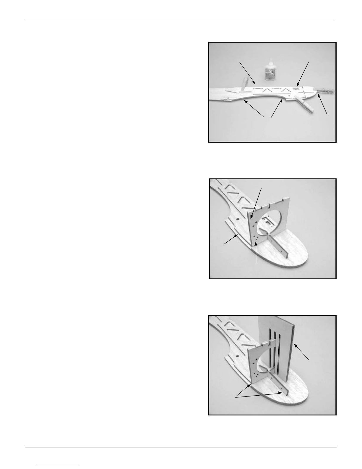
Aircraft SR X250 (aileron version)
Prop Graupner 9x5 Slim, Fixed
Motor Graupner Speed 400, 7.2V
Gear Ratio 2.33:1
Speed Control Jeti 350
Cell SR 500 Max Series
Cell Count 10
Pack Shape Rectangular, 5x2
Connector Sermos
Alternative Prop Graupner CAM 9x5, Folding
Receiver Hitec, 555
Servo Hitec, HS-60
Covering Material Goldberg, UltraCote Lite
Optimized Components
X250tm Assembly Instructions, Page 3
Warning, Warning, Warning!!!
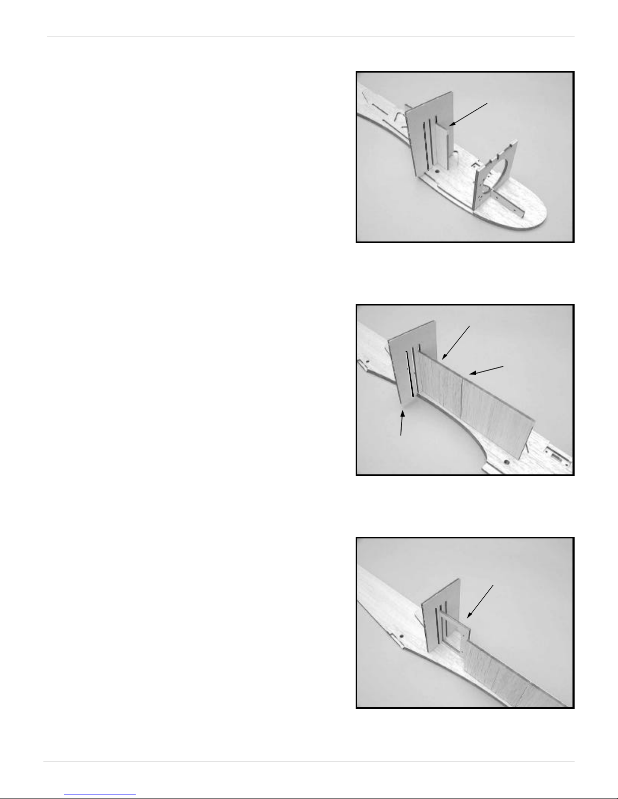
This is the single most important step in building your X250. The
entire trueness of the fuselage depends on you properly aligning the
fuselage doublers to the sides of the fuselage before you glue them to
each other. Take your time and don’t rush this step even though it
may seem very simple. DON’T MAKE TWO LEFTS!!!
There is a right and left fuselage side and a right and left doubler.
You can identify the left fuselage side and doubler by the cutout for
the speed control switch. Carefully align the doubler with the fuselage
side. Hold them together with clothes pins and check that they are
absolutely lined up with each other in the nose, wing saddle, and
fuselage top areas. When you’re satisfied with their registration, glue
them together. Glue the doubler around its edge and around all of the
cutouts in the doubler.
Left doubler and side
have the switch cutouts
Align
Align Align
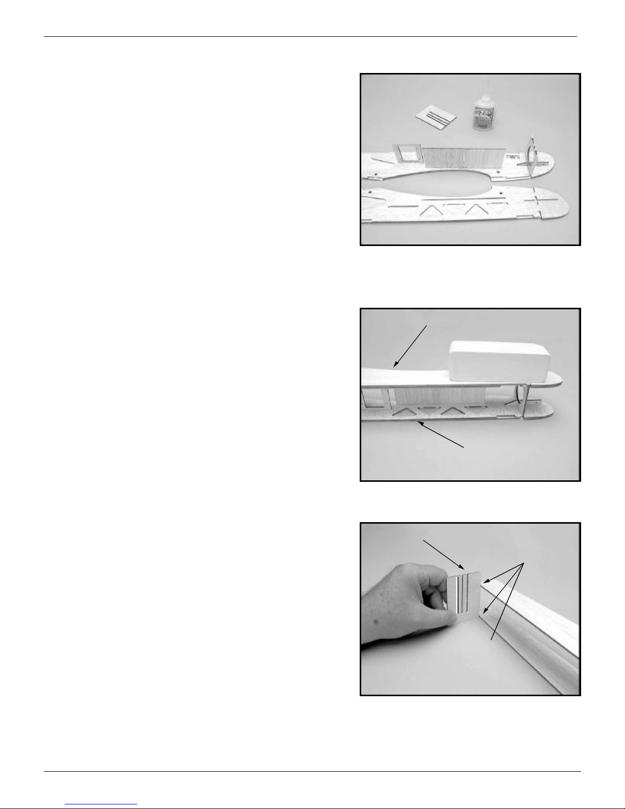
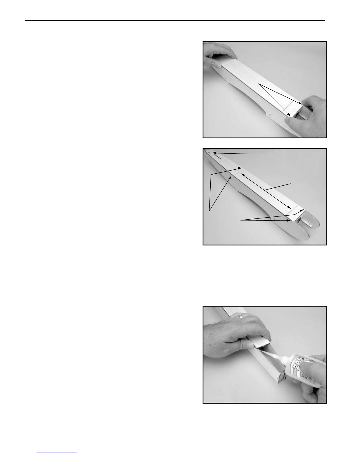
Trial fit the left motor mount and firewall...
Insert, but don’t glue, the left motor mount and firewall into the
left doubler. Note that the lower right corner of the firewall (viewed
from the front) has 3 holes for mounting the nose gear!
The forward, bottom edge of the firewall needs to be reshaped.
When the 1/8” bottom sheeting is added to the fuselage, it will rest on
the bottom of the firewall. If you locate and trial fit the bottom
sheeting, you’ll see how much of the bottom, forward edge of the
firewall will have to be sanded away to form the proper angle.
3 Holes!
Bottom sheeting
will go here
Forward bottom edge has to
be sanded at an angle to
match bottom sheeting
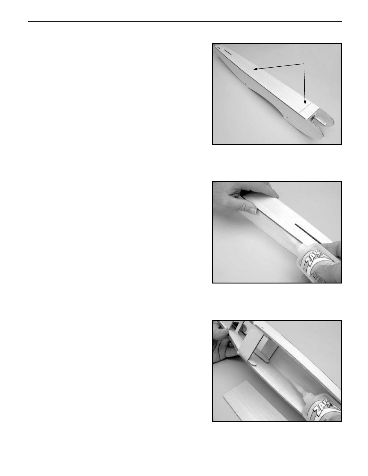
Use the alignment jig...
We’ve given you a plywood alignment jig to keep everything
aligned properly. The jig has three slots. The center slot is used with
plywood parts. The largest slot is for aligning the vertical stabilizer
after it’s covered and the narrowest slot is used with 3/32” parts. The
outer corners of the jig are cut at exactly 90° which will come in
handy later.
With the firewall and motor mount firmly seated in their recesses
in the doubler, use the alignment jig to make sure the firewall is
square with the doubler. Tack glue the firewall and motor mount to
the doubler in a corner of each and let the glue set. Remove the jig
and then glue the motor mount and firewall in place along their entire
edges. Don’t forget to glue the motor mount to the firewall too.
Tack glue
Alignment
Jig
X250tm Assembly Instructions, Page 4
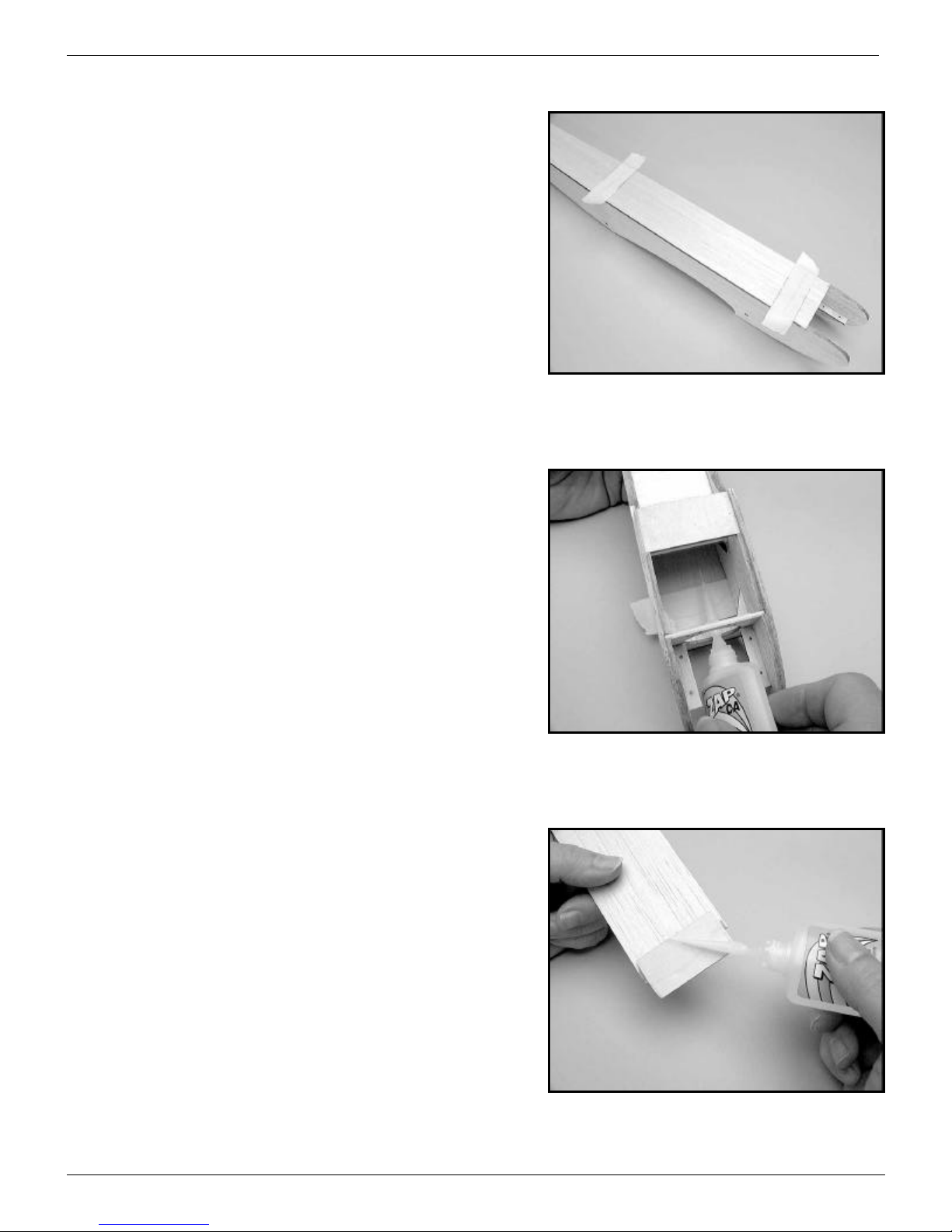
Front battery pack mounting plate...
Use the alignment jig to make sure the front battery pack
mounting plate is square to the side of the fuselage and that it is
firmly seated in the recess in the doubler. Tack glue the mounting
plate in place. When the glue has set, remove the jig and finish gluing
the mounting plate in place.
Front battery pack mount
Rear battery pack mounting plate...
Use the alignment jig to position the rear battery pack mounting
plate in place. You don’t have full support along the bottom of the jig
so be careful. A double check that the alignment is correct is that the
rear motor mounting plate should line up with the front motor
mounting plate.
Rear battery pack mounting plate
The front and
rear plates should
line up with each
other
Be careful! No support
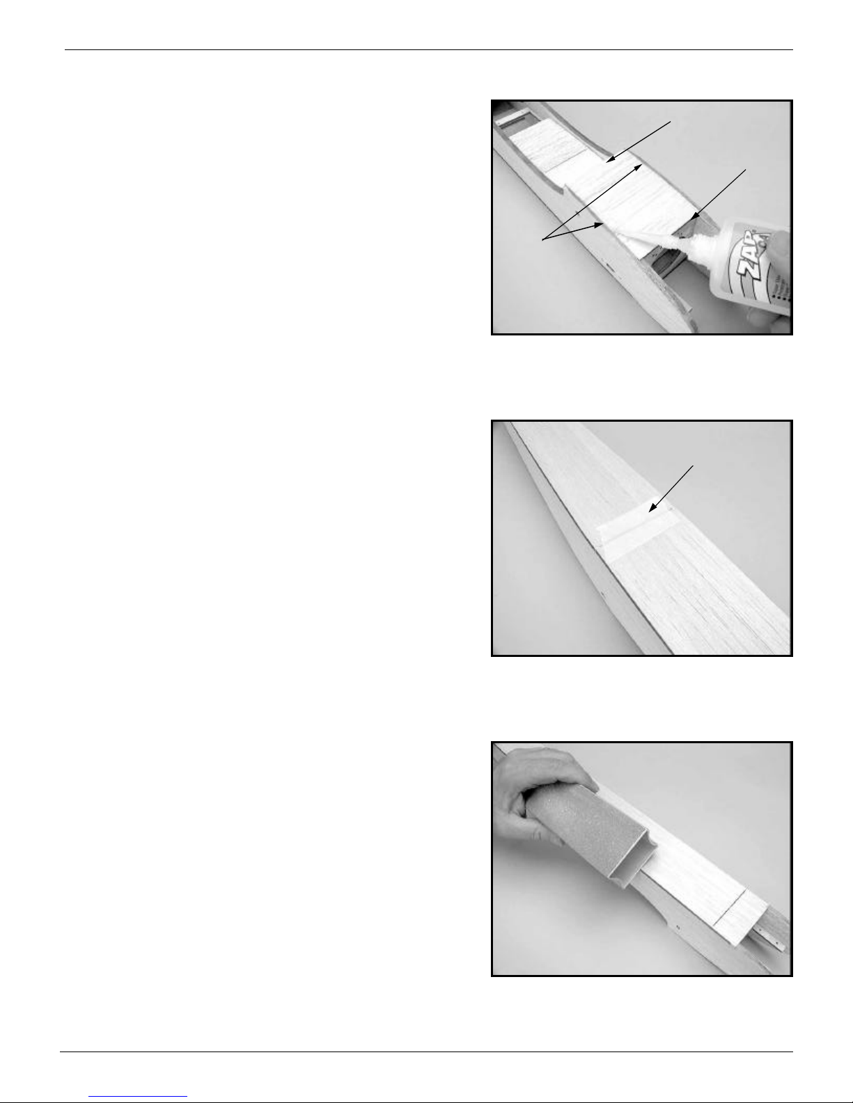
Servo mounting tray...
The servo mounting tray is setup for Hitec HS-60 servos. Check
to see if the cutout is properly sized for the servos you’re going to
use. We’ve left plenty of extra material in the plate so just open up the
hole until it fits the servos you’re going to use.
Use the alignment jig to hold the servo mount perpendicular to
the side of the fuselage while the glue sets. Again, tack glue first.
Then remove the jig and complete gluing the servo mount in place.
Servo mounting tray
X250tm Assembly Instructions, Page 5
The left side is done...
Here’s what the left fuselage side should look like at this point.
The left motor mount, firewall, battery pack mounting plate and servo
tray are in place.
Attach the right fuselage side...
Following these instructions will assure a straight and true
fuselage without any twists.
Dry!!! fit the right side of the fuselage. Insert the right motor
mounting plate, firewall, battery pack support plate, and servo tray
into their corresponding recesses in the right side doubler. Make sure
that the parts are firmly seated in their recesses and that nothing is
preventing them from completely seating.
Before gluing any parts together, use a weight to hold the parts
in place and use the right angle jig to check how closely the two
fuselage sides line up at the tail. Put the jig flat on the building
surface and see how close each of the fuselage sides comes to the jig.
If you were careful about lining up the doublers with the fuselage
sides and all of the parts were firmly seated in their recesses before
you glued them into the left fuselage side, the fuselage sides should
line up very closely with one another.
If the fuselage sides are close to being square (within an 1/8” or
so), go ahead and glue the right side and doubler in place. If the two
are way off (1/4” or more), try to sand and adjust the ends of the parts
and the recesses in the doubler until you can align the two fuselage
sides with one another. They should be within 1/8” of being square.
However, if you’re within an 1/8”, just pull the fuselage sides into
perfect alignment before you glue the right side in place.
Right angle jig
With one fuselage side
flush up against the
right angle jig, the other
fuselage side should be
within 1/8” of the jig.
Weight
Right fuselage side
Leftfuselageside
Don’t Glue Anything Yet!!!

X250tm Assembly Instructions, Page 6
1” Wide ply plates...
There are three, 1” wide plates that you should glue in next.
Before you do, lightly sand them to remove any oil or glazing from
their surfaces.
The upper rear plate is for securing the hatch and the lower two
plates are to reinforce the fuselage and provide mounting points if you
should choose to add floats for flying off of water at a later date. Do
not glue the upper front plate in! It will be glued to the hatch rather
than the fuselage top!
Glue rear hatch mounting
plate into place
Do Not glue this
plate into place!
Glue these two plates
into place.
Glue tail former into place...
Hold the sides of the fuselage together and tape the tail former
into place. Make sure you don’t glue in the tail former upside down
as there’s a right way and a wrong way! If you’ve got it right, the
former will be flush with the top and bottom of the fuselage sides.
With the tape holding the tail together, check the alignment of the
fuselage. Either lay the fuselage over the top view on the plans or
draw three parallel lines on your building board. The tail former
should be centered. If need be, pull it to the right or left to center it
and glue it in place. You’ll be able to correct minor misalignments
when you glue the top and bottom sheeting in place, but that’s no
reason to not make it as right as possible now.
Tail former should be
centered and not
upside down!
X250tm Assembly Instructions, Page 7
Glue the top at the tail...
The fuselage top is straight. The fuselage sides may be off a little
so pull the fuselage sides left or right a little until they line up with the
fuselage top. Tack glue the top to the sides only at the tail at this
point.
Trial fit the fuselage top...
How well does it fit? Notice that there is a right and left side to
the fuselage top! The right side has an exit hole for the rudder
pushrod at the tail.
The fuselage top should fit squarely up against the fuselage sides
where the cheek cowls begin and it should be centered on top of the
fuselage sides at the trailing edge of the wing. Don’t worry about
alignment at the tail. You’ll be able to fix that as long as the fuselage
top is square and centered over the forward partof the fuselage. If the
top doesn’t fit squarely, use a small sanding block to adjust the
fuselage sides at the cowl check notches.
A note before you glue! You do not want to glue the hatch area
of the fuselage top or the rear end of the fuselage top to the fuselage
sides. At this point, you only want to tack glue the fuselage top to the
fuselage sides just in front of and just behind the hatch. Use the
smallest amount of glue so that it doesn’t spread to the hatch area.
Hatch area. Do
Not Glue along
the edges
Only tack glue in
these four places
The rudder pushrod exit hole is on
the right side of the fuselage top
Fit should be flush up
against cheek cowls
X250tm Assembly Instructions, Page 8
Glue the fuselage top to the sides...
Starting at the tail. Squeeze the fuselage sides together a little if
need be so that they line up with the fuselage top and glue the top to
the sides. Work on your building board so that you can be pressing
down on the fuselage top for a good fit. Continue all the way around
the fuselage top both in the front and the rear of the fuselage.
Glue from the inside too...
After you’ve finished gluing the fuselage top to the sides from
the outside, turn the fuselage over and glue the two together from the
inside too.
Cut away the hatch...
Complete the cuts we’ve started for you for the hatch and remove
the hatch. Complete these two cuts
and remove the hatch

X250tm Assembly Instructions, Page 9
All done...
This is what the bottom sheeting should look like. You’ll sand it
to final shape a little later.
Glue the bottom rear sheeting in place...
There are five pieces of bottom rear fuselage sheeting. Starting
with the widest one, line it up with the fuselage sides just after the
cutout for the trailing edge of the wing. Glue it in place pulling the
fuselage sides together a little if need be. Don’t forget to glue the
sheeting to the plywood reinforcing plate too.
Glue bottom sheeting
to plywood reinforcing
plate too
Add scrap to tail...
Continue gluing each of the pieces of bottom sheeting in place
working your way to the tail. Don’t forget to glue each piece to the
previous sheet as well as the fuselage sides. Squeeze the sides
together as you move along so that they are either flush with the
bottom sheeting or so that the bottom sheeting sticks out a little so
that it can be sanded flush with the fuselage sides at a later stage.
When you install the last sheet, you may find that you’re a little
short of the tail. If so, glue a small piece of oversized 1/16” scrap in
place to finish the job. You can trim the scrap to size after the glue
hasset.
Scrap 1/16” balsa

X250tm Assembly Instructions, Page 10
The hatch retaining plate...
Using a sanding block, round over the edges and forward corners
of the hatch retaining plate both top and bottom. Trial fit it into the
recess in the fuselage sides. It should slide in easily and sit on top of
the doublers without any part of the retaining plate sticking up above
the height of the fuselage sides. It should also slide forward easily so
that only half of the plate is exposed. You don’t want a sloppy fit, but
you also don’t want a tight fit. Adjust the plate until you’re happy
with the fit.
Leave the plate in place in its forward position and proceed to the
next step. Don’t glue anything yet.
Round over the top edges
Round the forward
corners too
The hatch retaining
plate should fit easily
into the recess in the
fuselage sides
It should also slide
forward easily too
X250tm Assembly Instructions, Page 11
Tape the hatch back in place...
Use masking tape to tape the hatch back in place. Make sure it’s
lined up perfectly with the fuselage sides and it’s centered fore and aft
in its cutout.
Tack glue the retaining plate to the hatch...
From the bottom of the fuselage, tack glue the hatch retaining
plate to the hatch. Don’t use a lot of glue or you’ll end up gluing the
hatch to the fuselage!
When the glue has set, turn the fuselage over and remove the
hatch. Note: To remove the hatch, you only have to lift it slightly at
the rear and then slide the hatch rearward. If you lift the rear of the
hatch too high, you’ll break the retaining plate free of the hatch.
Glue the retaining plate to the hatch...
Glue the retaining plate to the hatch around its entire perimeter. If
the hatch has any bow to it, (it really shouldn’t) press the hatch and
retaining plate down on your building board before you start to glue.
This will flatten out the hatch and the retaining plate will keep it flat.
Reinstall the hatch. How did it fit? Use a sanding block if need be
to adjust the retaining plate so that the hatch can be installed and
removed easily and is centered on the fuselage.
X250tm Assembly Instructions, Page 12
Sand the top sheeting and hatch...
Use a sanding block to sand the top sheeting and hatch. First,
sand the sides of the fuselage to make the curve of the top sheeting
and hatch match perfectly the curve of the fuselage sides. Then, round
over the cornersand sand the top of the fuselage. But, before you do,
see the next step!!!
Forward, bottom sheeting...
The forward, bottom fuselage sheeting will fit between the two
fuselage sides and it will rest on the edges of the doublers. It should
be flush with the face of the firewall and it should extend past the
cutout for the leading edge of the wing. Don’t trim this excess length
until after you’ve completed the wing.
Now you know why you chamfered the bottom edge of the
firewall before you glued it into the doubler. If you put the correct
angle on the bottom edge of the firewall, it will meet perfectly with
the bottom sheeting.
Glue the bottom sheeting in place.
Flush
Don’t trim
Recessed between
the fuselage sides
Secure the hatch...
Before sanding the fuselage’s top sheeting and hatch, tape the
rear of the hatch to the rear sheeting to prevent it from shifting
sideways when you’re sanding its edge. Tape rear of hatch to fuselage
top to keep it from moving
X250tm Assembly Instructions, Page 13
Don’t sand the stab mounting area...
Sand the fuselage top and hatch but don’t sand the area of the
fuselage where the horizontal stabilizer will be mounted! Don’t sand these two areas!!!
Sand the cheek cowls to shape...
Don’t be afraid to remove material with your sanding block.
There’s plenty of “meat” in the X250’s fuselage so don’t be afraid to
give the fuselage a nice curve.
Round off the cheek cowls and fair them smoothly into the
fuselage top sheeting and hatch.
Cheek cowls
X250tm Assembly Instructions, Page 14
Sand the rear bottom sheeting...
Just as you did on the top of the fuselage, first sand the sides of
the fuselage so that the bottom rear sheeting is flush with the sides of
the fuselage. Then, sand the bottom sheeting itself to remove any
excess glue on the surface of the sheeting. Finally, round over the
edges to give the fuselage a nice appearance.
First, sand the edges of the
bottom sheeting to match
the sides of the fuselage
Second, sand the
sheeting smooth
Last, round over
the edges
Nose gear reinforcing plates...
Line up the two nose gear reinforcing plates behind the lower
portion of the firewall. Make sure the 3 holes are on the left. Pass a
landing gear leg through the holes in the firewall and reinforcing
plates to make sure they all line up. When you’re happy with the fit
and alignment, glue the plates to each other, the firewall, the fuselage
sides, and the fuselage bottom sheeting, all at one time. In a hard
landing, we want the landing gear to bend rather than bust anything
up in the fuselage. These reinforcing plates tie everything together.
3 Holes!
Nose gear reinforcing plates
X250tm Assembly Instructions, Page 15
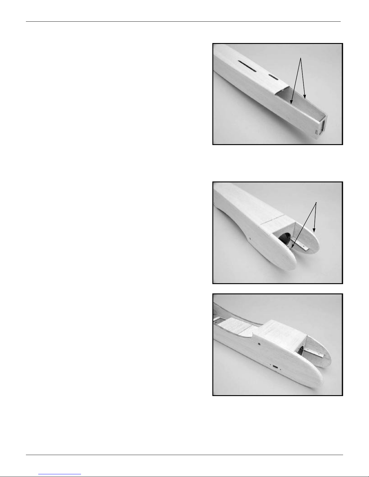
Horizontal and vertical stabilizers...
Laser cutting will usually leave a slight angle on the edges of
parts. For a good glue joint, you’ll want to square the edges of the
horizontal and vertical stabilizer parts where they meet each other.
Use a sanding block and only remove enough material so that the
honey color is removed from the edge of the part. This way, you’ve
sanded away any angle on the edge and made it square without
removing more material than necessary.
When you’ve finished the horizontal stabilizer, do the same for
the parts that make up the vertical stabilizer.
Horizontal stabilizer
Stab tip
Block sand square
Block sand square
X250tm Assembly Instructions, Page 16
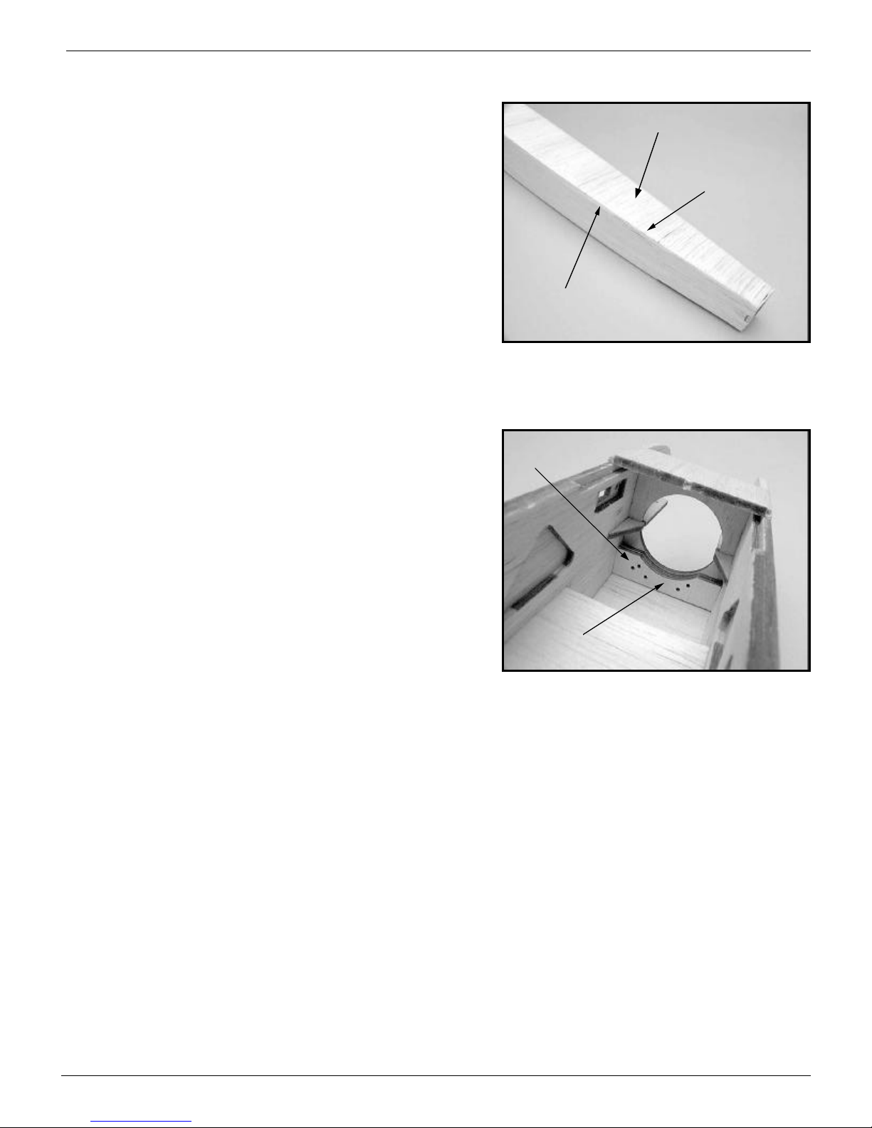
Glue the parts together...
When you’re happy with the fit of the parts, glue the tips to the
horizontal stabilizer. Do the same for the three parts that make up the
vertical stabilizer. Horizontal Stabilizer
Vertical Stabilizer
Prepare the rudder and elevator...
The rudder and elevator will be shaped next. First, you’ll want to
sand the mating surfaces, where the elevator meets the horizontal
stabilizer and the rudder meets the vertical stabilizer, square with your
sanding block. Don’t sand the outer edges yet.
Sand mating surfaces square to each other
Elevator
Rudder
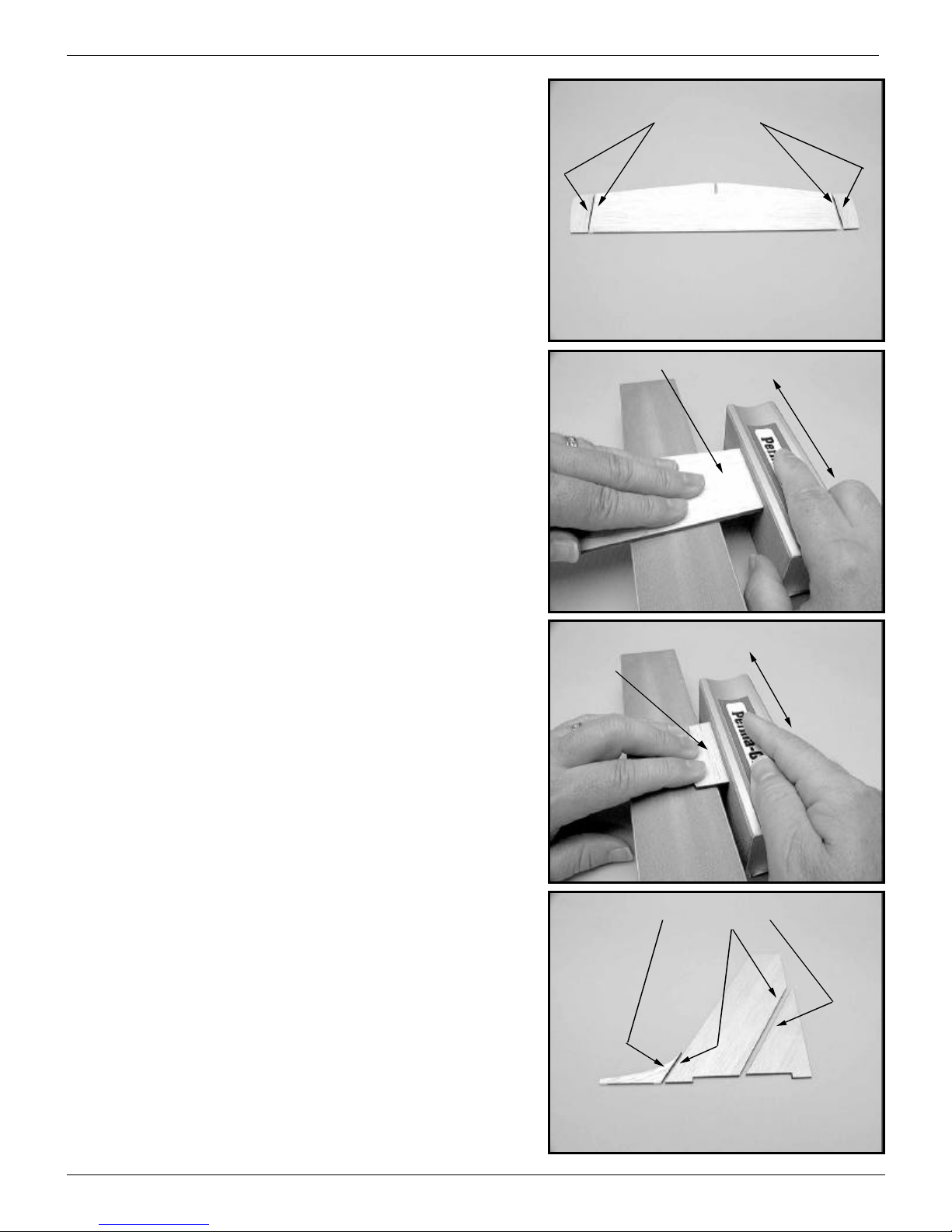
Horizontal stabilizer/elevator...
The rear edge of the horizontal stabilizer will be left square. The
front edge of the elevator will be sanded back at a 30° angle so that
looking at the top of the horizontal stabilizer the two are flush up
against each other. Viewed from the bottom, you can see that the
angle sanded into the leading edge of the elevator forms a “V” groove
where the two meet.
Note that you should add a piece of tape to the center of the
horizontal stabilizer’s leading edge so that this area will be left square
when the rest of the stab is sanded and its outer edges are rounded
over. The tape should be as wide as the width of the top fuselage
sheeting where it meets the horizontal stabilizer.
At this point, round off the edges of the horizontal stabilizer and
taper the elevator’s cross section so it’s only about 1/16” thick along
its trailing edge. Round off the elevator’s tips too.
Top View
Bottom View
Flush
“V” Groove
Tape
Horizontal Stabilizer Elevator
X250tm Assembly Instructions, Page 17
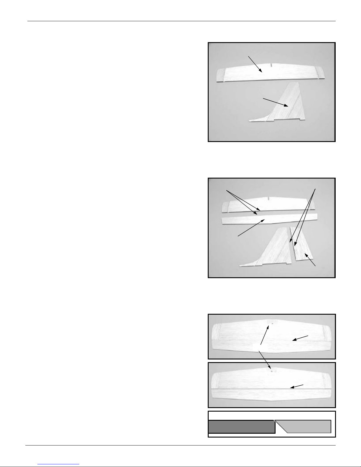
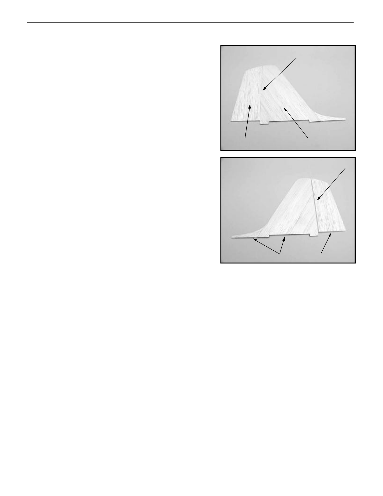
Vertical stabilizer/rudder...
Next, you’ll do the same thing to the vertical stabilizer as you did
the horizontal stabilizer. In this case, the two will meet flush on the
right side of the vertical stabilizer and there will be a groove on the
left side ofthe rudder.
Taper the rudder as you did the elevator and don’t round off the
bottom edges of the vertical stabilizer or rudder.
Don’t glue the horizontal stabilizer or vertical stabilizer to the
fuselage until after the fuselage is covered.
Right side, no groove
The left side of the rudder has the groove
Rudder Vertical Stabilizer
Don’t round off
Table of contents


