Aerotech ASTROBEE D Parts list manual

1
19915-1092
Rev.6/99
ADVANCED MODEL ROCKET
Astrobee D and the Aerojet logo
are trademarks of Gencorp and
Gummiwerke AG.
BEFORE YOU BEGIN:
• Study the illustrations and sequence of assembly. The
sequence of assembly is important. Review the parts list
and become familiar with all parts before assembly. If any
parts are missing or damaged, contact AEROTECH™ at
1-702-641-2301.
•DO NOT MODIFY THE DESIGN OF THE ROCKET.
Changestothedesignoftherocketsuchas,butnotlimited
to, reducing the fin size, shortening the body tube, or
modifyingthemotortubeassemblycanadverselyaffectthe
flight stability of the rocket.
• Only use AEROTECH™ Composite Model Rocket Motors
in this model rocket. See Motor Matrix for recommended
AEROTECH™ motors.
Assembly and Operation InstructionsAssembly and Operation Instructions
ReadandfollowtheModelRocketSafetyCode
ofthe NationalAssociation ofRocketry (NAR)
and comply with all federal, state and local
laws in all activities with model rockets.
PARTS:
Thrust Ring (7/16"/11mm) (14010) 1
Thrust Ring Flange (1/16"/1.6mm) (14011) 1
Motor Tube (12912) 1
Motor Hook (19001) 1
FIN-LOK Rings (4 Fin) (19344) 2
Centering Rings (2-17/32"/64mm) (16629) 3
Fins (11715) 4
Cooling Mesh (19011) 1
Ejection Gas Baffle (19030) 1
Screw Eye (19015) 2
Shock Cord (8') (17388) 2
Lower Body Tube (Slotted) (12628) 1
Upper Body Tube (Launch Lug) (12629) 1
Bulkhead Disk (1/16"/1.6mm) (16609) 1
Coupler Tube (6"/15cm) (12606) 1
Launch Lugs (19035) 2
Nose Cone (11261) 1
Decal Sheet (18015) 1
30" Parachute (Lower Body) (13030) 1
22" Parachute (Upper Body) (13022) 1
Scale Plastic Launch Lug Piece (18915) 1
Scale Plastic Antenna Mounts (18925) 2
Aluminum Antenna Tubes (18930) 2
Scale Plastic Fasteners (18935) 12
Chrome Adhesive Band (18940) 1
'F' Spacer Tube (1") (14003) 1
Scale Drawing (19815) 1
Instructions (19915) 1
Additional Tools Required:
Pliers
ASSEMBLY INSTRUCTIONS: (Use medium viscosity cyanoacrylate cement.)
COMPLETED
ASTROBEE D
ADVANCED
MODEL
ROCKET
Read And
Follow All
Instructions

2
NOTE: FROM THIS POINT ON, DO NOT USE ANY
CEMENT UNTIL REACHING ASSEMBLY STEP 5.
1. With their motor hook channels aligned with the motor
hook, slide a FIN-LOK™ ring and then an AERO-FI-
BRE™ centering ring over the front end of the motor
tube. Pushonthecenteringringuntilthebackedgeofthe
FIN-LOK™ringismoved to the forwardmostmarkmade
in Step 3 above. (NOTE: The rings are designed to be a
tight fit on the motor tube. If the rings are difficult to slide
onto the motor tube, round the inside edges of the rings
withsandpaper. IftheFIN-LOK™ringsneedtobeturned
aftertheyareonthemotortube,useasmallpieceofcloth
to provide a better grip.)
2. Slide the other FIN-LOK™ ring and then a centering ring
over the back end of the motor tube. Push on the
centering ring until the front edge of the FIN-LOK™ ring
is at the rear-most mark made in Step 3.
3. Usingthelineonthemotortubeasaguide,gentlytwistthe
back centering ring slightly until the fin locks of the back
FIN-LOK™ ring are aligned with the fin locks of the front
FIN-LOK™ ring.
LOCATION
GUIDE 1/4"
6 mm 1/2"
13 mm
FIN-LOK™ ASSEMBLY
1. Cement the thrust ring flange (1/16"/1.6 mm thick) to the
thrustring(7/16"/11mmlong). Setthe thrustringassem-
bly aside to dry.
2. Findthelinedrawnalongthesideofthemotortube. Using
the Location Guide printed along the top edge of this
instruction sheet, cut a 1/4" (6 mm) long slot 4-5/8"
(117mm)from the back end of themotor tube andnext to
the line on the motor tube as shown.
3. Using the Location Guide, make a mark along the motor
tube line 3-9/16" (91mm) from the back end of the motor
tube. Thismark locateswherethe back edge ofthefront
Thrust
Ring
Flange
Motor
Tube
Line
Thrust
Ring
Motor
Hook
Slot For
Motor
Hook
AERO-FIBRE™
Centering
Ring
Motor
Tube
1-1/2"/38mm And 3-9/16"/91mm
From Back Edge Of Motor Tube
FIN-LOK™Ring
Location Marks
4-5/8"/117mm
From Back Edge of
Motor Tube
Front
End
3"
76 mm
1-1/2"
38 mm 3-9/16"
91 mm
Front Edge of
Back FIN-
LOK™ Ring
Back Edge Of
Motor Tube Tube Coupler
Marking Guide Back Edge Of
Front FIN-LOK™
Ring
Motor
Hook
Slot
4-5/8"
117 mm
MOTOR TUBE ASSEMBLY
FIN-LOK™ringwillbe. Makeanothermark1-1/2"(38mm)
from the back end of the motor tube. This mark locates
wherethefrontedgeoftherearmostFIN-LOK™ringwill
be.
4. Insert the tab of the motor hook into the slot cut into the
motor tube. Use a small dowel to apply several drops
of cement around the inside of the motor tube just
behind where the motor hook comes through the
motor tube wall. Then, with the thrust ring flange facing
thebackofthemotortube, insertthethrustringassembly
into the motor tube until it stops, against the motor hook
tab.
FIN-LOK™
Ring
Front
End
FIN-LOK™
Ring
Motor
Hook
Channels
A/D-2

3
Shock
Cord
Ejection
Gas Baffle
Shoulder
Motor
Tube
FIN-LOK™ ASSEMBLY (CONT.)
Screw
Eye
Centering
Ring
1. Make four 1/4" (6mm) long cuts, 90 degrees apart, in the
front end of the motor tube.
2. Stretchoutthecoolingmeshtoabout6"(15cm)inlength.
Insert the cooling mesh into the front end of the motor
tube. (NOTE: Do not cement the mesh into the motor
tube.)
3. Apply a thin film of cement to the front 2/3rd's of the
shoulder of the ejection gas baffle and insert the baffle
shoulder into the front end of the motor tube.
4. Apply beads of cement where the baffle meets the
motortubeandintoeachofthecutsinthemotortube.
5. Apply cement to the front surface of the baffle flange and
placeanAERO-FIBRE™centeringringoverthefrontend
of the baffle so it rests upon the baffle flange.
6. Screw the screw eye all the way into the hole at the front
endofthebaffle. Securelytie an end of the shock cordto
thescreweyewithasquareknot. (CAUTION:Donotput
cementontheknotoftheshockcord. Cementwillweaken
the shock cord.)
Permanent
Cooling Mesh
(Stretch Out - 6")
FIN DETAIL
Lower Half
of FIN-LOK™ tab
(discard)
Cut off and Sand "nub"
on each side of fin.
Sand here to
remove rough
edges.
DO NOT CEMENT COOLING
MESH INTO MOTOR TUBE
LABYRINTH™ ASSEMBLY
6. Apply a bead of cement where the front centering ring
meetsthemotor tube. Withoutgettingcementinto anyof
the finlocks, apply cement only to the areas BETWEEN
the finlocks where the front FIN-LOK™ ring meets the
front centering ring and the motor tube.
7. Without getting cement into any of the fin locks, apply
cement only to the areas BETWEEN the fin locks where
onlythefrontedge ofthebackFIN-LOK™ringmeetsthe
motortube. DONOTapplycementtothebackedgeofthe
back FIN-LOK™ ring. (NOTE: The unique AEROTECH
FIN-LOK™ fin mounting system carries and distributes
aerodynamic and thrust loads throughout an integrated
rocket structure in a manner found in large aerospace
vehicles. Loads are primarily borne by structural mem-
bers and not cement.)
8. Applyabeadofcementaroundthemotorhookforwardof
the front centering ring.
5. Test the proper positioning and alignment of the FIN-
LOK™ rings by snapping the fins into the fin locks. If any
fin does not snap into place, check to see that each FIN-
LOK™ringisthecorrectdistancefromthebackendofthe
motortubeandthatthefinhasnoplasticflashingleftfrom
production that may be preventing a proper fit. Remove
anyplasticflashingwithahobbyknifeorsandpaper. After
making any adjustments, carefully remove the fins and
the back centering ring. Check that the front centering
ring is still positioned next to and touching the front FIN-
LOK™ ring.
4.
1/4"/6mm
Cuts
Front
End
Fin
Locks
Front
Centering
Ring
Cement
Beads
Baffle
Flange
A/D-3
Use a pair of pliers to snap off the lower half of the FIN-
LOK™ tab from each of the four (4) fins as shown.
Discard the pieces that were broken off. Sand the edge
of the tabs to remove any rough edges from where the
lowerhalfofthefintabswereremoved. Cutandsandthe
nub on each side of the fin until smooth.
DO NOT ALLOW CEMENT
TO GET IN THE FIN LOCKS

4
LOWER BODY PREPARATION
1. Forasmooth finish, fill in thespiralinthebody tube seam
withafillermaterial. Sandtheseamflushwiththesurface
of the body tube.
2. Using a hobby knife, carefully remove any body tube
material from the slot where the launch lug is to be
attached.
3. Lightlysandthesurfaceofthelowerbodytubearoundthe
launch lug slot.
4. Applycementtothebaseofalaunchlug. Withthesloping
portionofthelaunchlugtowardthefrontofthelowerbody
tube, insert the tab on the bottom of the lug into the pre-
cut launch lug slot in the lower body tube.
5. Apply a base primer coat of paint to the lower body tube.
After the base coat has dried paint the entire body tube
insignia white. Allow to dry thoroughly. The back 3.52"
(89mm)ofthe body tubeispaintedmatteblack. Mask off
and paint this area accordingly.
UPPER BODY PREPARATION AND ASSEMBLY
1. For a smooth finish, fill in the spiral in the body tube with a
fillermaterial. Sand thefillermaterialflushwiththesurface
of the body tube.
2. Using a hobby knife, carefully remove any body tube
materialfromtheslotwherethelaunchlugistobeattached.
3. Lightlysandthesurfaceof the upper body tube around the
launch lug slot. Apply cement to the base of the remaining
launchlug. Withtheslopingportionofthelaunchlugtoward
thefrontoftheupperbodytube,insertthetabonthebottom
of the lug into the pre-cut launch lug slot in the upper body
tube.
4. Apply a base primer coat of paint to the upper body tube.
After the base coat has dried paint the entire body tube
insignia white. Allow to dry thoroughly. The forward 6.38"
(162mm) of the body tube is painted matte gray. Mask off
and paint this area accordingly. Let dry.
5. Screw the other screw eye all the way into the hole in the
bulkhead (1/16"1.6mm thick). Apply a bead of cement
where the screw eye meets the bulkhead.
6. Pass the free end of the remaining shock cord through the
couplertube(6"/15cmlong) and securely tie it to the screw
eye attached to the bulkhead with a square knot. (CAU-
TION: Do not put cement on the knot of the shock cord.
Cement will weaken the shock cord.)
7. Cement the bulkhead plate to the end of the coupler tube.
8. Make a pencil mark 3" (76mm) from an end of the coupler
tube. Lightlysand the surface of the coupler tube between
the mark and the bulkhead. Use a small dowel to apply a
bead of cement around the inside of the upper body tube
about1"(25mm)fromthebackendofthetube. Thenslide
the coupler into the upper body tube up to the pencil mark
on the coupler tube.
A/D - 4

5
LOWER BODY AND FIN ASSEMBLY
A/D-5
1. Mask off the FIN-LOK tab on each of the four Astrobee D
fins. Carefully wash the fins in a detergent/soap bath to
removeany oilsleftoverfrom themoldingprocess. On the
decalsheetlocatthe4leadingedgecuffs(labelled'M'). Cut
these cuffs and crease each of them along the center
dashedline. Removethebackingfromacuffdecal. Center
the dashed line over the leading edge apex of the fin.
(Review instruction drawing for proper orientation.) Press
thecenterof the decal to the leading edge of the fin. Press
downthesides of the cuff decaloverthefrontof the fin. Be
sure to check the position of the decal as this is done and
press out any air pockets which may be under the decal.
Repeatthisstepfortheremainingfins. Painteachfinmatte
light tan. Set aside to dry.
2. Using a hobby knife, carefully remove any body tube
materialthatmaystillbeattachedtoanypre-cutslotsinthe
body tube.
3. Insert the loose end of the shock cord and then the motor
tube assembly into the back of the rocket body tube as
shown. Position the motor tube assembly so that the fin
locksare locatedunderandvisiblethrough thebodytube's
pre-cut fin slots.
4. Apply cement along the full length of the fin root of a fin
(area of the fin that makes contact with the outside surface
of the lower body tube). Carefully insert the fin through a
slotinthebodytubeandsnapthefinintoplace. Repeatthis
processfortheotherthreefins. (NOTE: Eachfinshouldbe
snug against the body tube.)
5. Throughthebackofthebodytube,applycementwherethe
fin tabs meet the motor tube, fin locks, front centering ring
and body tube. Through the front end of the body tube,
apply cement where the baffle assembly centering ring
meets the inside surface of the body tube.
6. Locate the length of plastic launch lug rail. Using a model
knifeorrazorsaw cutofftwopieces1 15/16"(49mm) long.
Cut out the aft launch lug top and bottom marking guides.
Trace their patterns on to each of the pieces of launch lug
railpreviouslycut. Usingasharpmodelknife,cutthesetwo
pieces to the proper shape. Wash these parts in a deter-
gent/soap bath. Rinse and let dry. Paint both pieces gold.
7. Notethelocationofthescalelaunchlugsonthelowerbody
tube. Carefully cut out the aft launch lug marking guide.
Remove the inner outlined area inside the guide using a
model knife. Place the marking guide between two fins
located90degreesaroundeithersideofthebodytubefrom
the flight launch lug (See drawing). Using a pencil, lightly
mark the outline of the aft launch lug rail on the end of the
bodytube. Applycementto thebottomofoneofthelaunch
lug rails. Press in place and hold until the cement sets.
Repeat this step for the remaining launch lug rail.

6
FINAL ASSEMBLY
A/D - 6
1.Slidetheremainingcenteringringoverthebackofthemotor
tubeand motorhookandpushit againstthebackFIN-LOK
ring. Applyabeadofementwherethecenteringringmeets
the body tube.
2. Cleanthe nose cone with a dampcloth. Mask off thenose
coneshoulder topreventanypaintfromgettingon it. Paint
thenoseconewithaprimercoatofpaint(grayorwhite). Let
the primer dry. Paint the nose cone with matte light gray
paint. (CAUTION: Make sure the paint is compatible with
high impact polystyrene plastic). Once the paint is dried,
cement the nose cone into the forward end of the upper
body tube.
3. Take the two plastic antenna shoe pieces and wash them
in a detergent/soap bath. Rinse and let dry. Paint both
pieces silver. Let paint dry.
4. Cut out the payload section antenna location and decal
placement guide. Carefully cut out the areas marked
"Antenna Location" on the guide. Be certain to note the
guide'sorientationonthepayloadsection. Wrapthisguide
around the payload section of the upper body tube. Using
a pencil, mark the outline of the two antenna shoes on the
payload section. Remove this guide and save it for later
reference.
5. The AeroTech Astrobee D kit may be completed in two
different configurations:
FLIGHT CONFIGURATION: Cut out decal 'L' from the
decalsheet. Positionthisdecalsothatitiscenteredover
the paint separation line between the gray payload
section and white airframe. Using the decal placement
drawing,beginwrappingthedecalaroundthebodytube.
Observe during the wrapping that the decal is aligned.
(See Decal Instructions for decal application informa-
tion.)
LAUNCH CONFIGURATION: Locate the self adhesive
aluminumband. NoteitspositionontheDecalLocation
Guide 5.87" (149mm) from the front of the upper body
tube. Remove the backing tape from the band. Start
wrapping the aluminum band around the body tube,
beginningatthepointindicatedonthedecalplacement
drawing. Continue to wrap the band around the body
until it is completely finished. (NOTE: The adhesive on
the band is very strong and care should be taken to
position the band properly as the adhesive can pull up
thepaint.) Therewillbeagapbetweentheendsofband
oncewrappedaround the bodytubeandthis is normal.
Find the remaining piece of the plastic launch lug rail.
Cut off a piece 1.31" (33.2mm) long. Wash this part in
a detergent/soap bath. Rinse and let dry. Cut off 10 of
the plastic fasteners from their holders. Wash these
parts as before and allow to dry. Using the Fastener
Location Guide, cement 5 of these fasteners to each
sideofthelaunchlugrail. Whenthecementisdry,paint
this assembly silver.
Apply cement to the bottom of the launch lug rail/
fastener assembly. Center this piece over the gap
between the ends of the aluminum band and press
firmly into place. Hold in position until the cement sets
up.
6. Carefully cut out the self adhesive decals and apply them
to the model in the positions noted on the Decal Location
Guide. Make certain to line up the upper and lower body
tubes for correct placement of decals.
7. Tie loops in the ends of both shock cords. Thread the 30"
(76cm)parachuteshroudlinesthroughtheloopinthelower
body tube shock cord. Stretch out the shroud lines of the
parachutesothatthelinesformthree(3)loopsontopofthe
other. Pass the canopy of the parachute through three (3)
loopsmadebytheshroundlines andpulltight. Repeatthis
procedure with the 22" (56cm) parachute and upper body
assembly.
8. Usingapairofpliers,carefullycrimponeendofeachofthe
antenna tubes into an open square shape. Carefully push
the crimped end of the aluminum tubes on to the fittings at
theendoftheantennashoes. Itmaybenecessarytocrimp
the ends more or to open them up depending on their fit.
ThesepeicesaretoberemovedwhenflyingontheAstrobee
D kit to prevent any damage to the antenna shoes.

7
OPERATION INSTRUCTIONS
1. RECOMMENDED MOTORS: Only use AEROTECH composite model
rocket motors when flying your AEROTECH rocket. See enclosed chart
for recommended motors and projected altitudes.
No warranty either expressed or implied is made regarding AEROTECH products,
except for replacement or repair, at AEROTECH’s option, of those products which are
proventobedefectiveinmanufacturewithinoneyearfromthedateoforiginalpurchase.
For repair or replacement under this warranty, please contact AEROTECH. Proof of
purchase will be required. Note: Your state may provide additional rights not covered
by this warranty.
NOTICE: AEROTECH certifies that it has exercised reasonable care in the design and
manufacture of its products. As we cannot control the storage and use of our products,
once sold we cannot assume any responsibility for product storage, transportation or
usage. AEROTECH shall not be held responsible for any personal injury or property
damageresultingfrom the handling, storage or use of our product. The buyer assumes
all risks and liabilities therefrom and accepts and uses AEROTECH products on these
conditions.
AeroTech, Inc.
Las Vegas, NV 89104
www.aerotech-rocketry.com Made in U.S.A.
©1999 AeroTech, Inc., All rights reserved.
2. RECOVERY SYSTEM PREPARATION: Roll the parachute and shroud
linesfortheupperbodyassembly. Startfromthecanopypeakandrollthis
parachuteandshroudlinesintoatightcylinderthatwilleasilyslideintothe
lower body tube/fin unit. Place this parachute into the lower body tube
followed by the shock cord. Roll the parachute and shroud lines for the
lowerbodytube/finunit. Startfromthecanopypeakandrollthisparachute
and shroud lines into a loose cylinder. Pack the lower body assembly
parachute on top of the upper body parachute and shock cord previously
installed in the rocket. Pack the lower body shock cord on top of this
parachute. Insertthe remaining shock cord length into thebody tube and
insert the coupler tube for the upper body assembly. Make sure that the
parachutes, shroud lines and shock cords are not caught between the
bodytube and the shoulderof the upper bodyassembly. The upper body
unitshouldslidefreely.(NOTE: BecauseyourAEROTECHrockethasthe
LABYRINTH™ ejection gas cooling system, no recovery wadding is
required.)
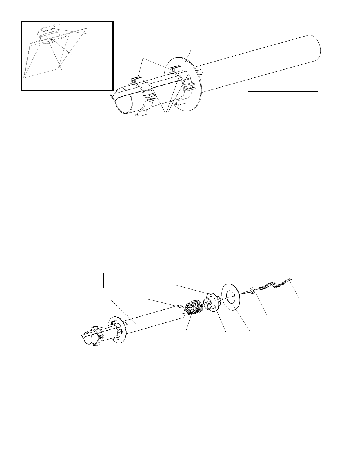
3. MOTOR PREPARATION: The motors recommended for your AERO-
TECH rocket vary in physical size as well as performance. Your rocket
comeswith a changeablemotor adaptor andspacer tubes thatpermit the
rocket to use each of the recommended motors without permanent
modification to the rocket.
Prepare your AEROTECH rocket motor according to the instructions that
come with the motor. Be sure the motor hook snaps in behind the nozzle
end of the motor and holds the motor securely in place. If the motor hook
does not hold the motor in place, bend the end of the hook until it does.
4. PRE-LAUNCH CHECKOUT: Before EVERY flight, perform a complete
pre-launch checkout of your rocket;
• Check that all fins and launch lugs are mounted securely and not
damaged.
• Examine the body tube, nose cone and payload bay to make sure
they are free of damage.
• Check that the shock cord is securely mounted to the ejection gas
baffle and nose cone (or payload bay bulkhead).
• Check that the parachute is securely tied to the shock cord.
• Check that the shock cord and parachute are free of any damage.
• See that the nose cone (or payload bay), packed parachute and
shock cord move freely. After awhile, an ejection charge residue
may build up at the top inside surface of the body tube. Wipe this
residue away with isopropyl ("rubbing") alcohol.
• With the tail of the rocket pointed down and the motor tube empty,
shake the rocket to remove any loose ejection charge debris left
from a previous flight. Periodically, fluff up the cooling mesh using
a bent wire inserted through the back end of the motor tube.
• Be certain the motor to be used is a recommended AEROTECH
model rocket motor and of a size appropriate for the launch area.
• Be sure the motor hook, motor adaptor and motor tube are not
damaged and hold the motor securely in place.
If the pre-launch checkout reveals any damage, repair the damage
before the rocket is flown again.
7. LAUNCH AREA: Launch the rocket in a cleared outdoor area free of tall
trees,powerlines andbuildings. Theside dimensionsofthe clearedarea
should be at least one half of the projected altitude. An area for a radius
ofatleast5feet(1.5meters)fromthelaunchershouldbeclearofdrygrass
orotherflammablesubstances. ReadandfollowtheModelRocketSafety
Code of the National Association of Rocketry (NAR) and comply with all
federal, state and local laws in all activities with model rockets. A copy of
the NAR safety code is shown on the instructions that come with all
AEROTECH composite model rocket motors.
8. FLIGHT PROFILE: When the launch button of the electrical launch
controller is pressed, an electrical current causes the AEROTECH COP-
PERHEAD™ single lead igniter to ignite the composite propellant of the
AEROTECHrocketmotor. Themotorquicklybuildsupthrust andpowers
your AEROTECH rocket into the air. During powered flight the rocket
increasesinspeedandaltitude. When thepropellantburnsouttherocket
is moving at maximum velocity and a time delay material (delay grain)
inside the motor burns. While the delay grain burns the rocket coasts to
peak altitude at which point the delay grain ignites the ejection charge
within the forward part of the motor. The ignition of the ejection charge
creates a burst of hot expanding gas which is cooled by the permanent
metal mesh of the LABYRINTH™ ejection gas cooling system. The
cooled gas flows around the baffle, pressurizes the parachute bay and
ejectsthenosecone(orpayloadbay)andparachute. Theparachutethen
deploys and gently returns the rocket to the ground where the rocket can
be prepared for another flight.
9. TRANSPORT AND STORAGE: To avoid damage to your AEROTECH
rocketduringtransport,pack itinabox surroundedbysoft packing. Store
your rocket at room temperature.
5. LAUNCHPAD: YourAEROTECHrocketmustbeflownfromalaunchpad
with a 1/4"(6.4mm) diameter metal launch rod at least 36"(0.9m) long (as
measured from the top of the blast deflector), such as the AEROTECH
MANTIS™ model rocket launch pad.
6. MOTOR IGNITION: Only launch your rocket using a remotely controlled
and electrically operated launch controller such as the AEROTECH®
INTERLOCK™ model rocket launch controller. Keep yourself and all
other people at least 30 feet (10 meters) away from the rocket during
launch.
A/D-7

8
1. Handlethedecal sheet carefullytoavoiddamage. Do notcreasethe decal sheet.
2. Use a pair of sharp scissors or a hobby knife to cut out the decals.
3. Cuttingoutdecalsthatwillbepositionedclosetogetherontherocketasoneblock
will make them easier to apply.
4. Makesmooth cuts. Smallknickscan causeadecal to tearwhen it isbeing peeled
off the backing sheet.
5. Before starting to peel decals off their backings, fill a soup bowl with warm water
and put one or two drops of a dishwashing detergent into the water.
6. Carefully peel a decal off its backing, dip it into the detergent solution and apply
thedecaltotherocket.The detergent solution prevents the adhesive on the decal
from "grabbing" the rocket surface too quickly and allows accurate positioning of
the decal.
7. Gentlypressany air bubblesoutfromunder the decalandthendab the decaldry.
8. Apply the rest of the decals in the same manner.
DECALINSTRUCTIONS

9
ATTENTION!
TheAEROTECHASTROBEE DAdvancedModelRocket loadedwithanAEROTECH "F"or"G"motor weighs morethanone
(1) pound at liftoff. When flying a model rocket that weighs over one (1) pound at liftoff you must observe certain FAA
regulations.
Federal Aviation Administration (FAA) regulations (FAR 101-subpart C) currently require that anyone planning to launch a
model rocket weighing over one (1) pound but no more than 3.3 pounds at liftoff must notify (such as by telephone call) the
nearestFAAAirTrafficControl(ATC)facilitynolessthan24hoursandnomorethan48hoursinadvanceofthelaunchofsuch
a rocket and provide the following information:
a) Thenamesandaddressesoftheoperators;exceptwhentherearemultipleparticipantsatasingleevent;thename
and address of the person so designated as the event launch coordinator, whose duties include coordination of
the required launch data estimates and coordinating the launch event;
b) The estimated number of rockets to be operated;
c) The estimated size and estimated weight of each rocket; and
d) The estimated highest altitude or flight level to which each rocket will be operated.
e) The location of the operation.
f) The date, time, and duration of the operation.
g) Any other pertinent information requested by the ATC facility.
Rockets weighing over one (1) pound but no more than 3.3 pounds at liftoff must not be launched within 5 miles of an airport
runway or other landing area unless the information listed above is also provided to the manager of that airport.
Inaddition,no personmayoperatean unmannedrocketthatweighs overone(1)pound but nomorethan3.3 poundsatliftoff:
1) In a manner that creates a collision hazard with other aircraft.
2) At an altitude where clouds or obscuring phenomena of more than five/tenths coverage prevails.
3) At any altitude where the horizontal visibility is less than five (5) miles.
4) Into any cloud.
ReadandfollowtheModelRocketSafetyCodeoftheNationalAssociationofRocketry(NAR)andcomplywithallfederal,state
and local laws in all activities with model rockets.
FLY SAFELY!
©1998 AeroTech, Inc., All rights reserved.
READ THIS BEFORE FLYING YOUR ASTROBEE D

10
ASTROBEE D MARKING AND CUTTING GUIDE
CUT
OUT
THIS
PIECE
FASTENER LOCATION GUIDE
AFT LAUNCH LUG CUTTING GUIDES

11
Table of contents
Other Aerotech Toy manuals
Popular Toy manuals by other brands

Hasbro
Hasbro Bed Bugs quick start guide

REVELL
REVELL Bristol BEAUFIGHTER TF.X Assembly manual

Viessmann
Viessmann 4570 Operation manual

Eachine
Eachine F-18 EDF user manual

Fisher-Price
Fisher-Price Little People M0532 instruction sheet

Carl Goldberg Products
Carl Goldberg Products Stinson 108 ARF user guide