SRS Lighting DST4WH-3 User manual

Instruction Manual
Models:
version 1.0 since 25 October 2018
ATTENTION!
This instruction manual contains important information about the installation and the use of the
equipment. Please read and follow these instructions carefully.
Always ensure that the power to the equipment is disconnected before opening the equipment or
commencing any maintenance work.
DST4W _en_manual_M312
Wireless -way DMX /
AC Power Splitter
DST WH-3, DST WH-5
DST WH-C

IMPORTANT SAFETY INFORMATION
The following general safety precautions have to be observed during all phases of
operation, service, and the repair of this equipment. Failure to comply with these
precautions or with specific warnings in this manual violates safety standards of
design, manufacture, and the intended use of this equipment.
Do not operate in an explosive atmosphere!
Do not operate this equipment in the presence of flammable gases or fumes.
Operation of any electrical instrument in such an environment constitutes
a definite safety hazard. Device should be never placed near or over a heat
register or other source of heated air and it should not be installed or operated
without proper ventilation.
Mains AC 85-265V connection
AC power is connected to the splitter via Neutrik PowerCon blue connector.
Standard supply is UNISC UKO lead with Neutrik PowerCon. Always respect the
markup of L and N on connector for correct wiring of Line and Neutral.
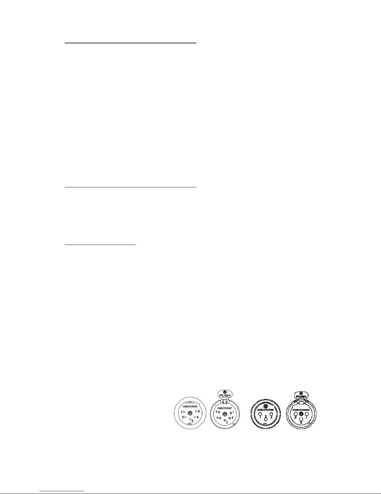
DMX connection
DMX connectors are located on both sides of the splitter board. These are
separated to two groups. First group is wired in ration 1:1 and marked as DMX input
and DMX thru. This line is not optically isolated and when the device is last in line,
it should be terminated by the termination resistor of 120ohm wired between pins 2
and 3 of the DMX thru connector.
The other group consists of 4-way optically isolated lines marked with letters A-D.
Each line has a separate power supply, line driver and the indication of signals D+,
D- on both signal lines. These LEDs are active when splitter is retransmitting DMX
signal and there is no short circuit between data lines.
In case of short circuit between data pins D+/D- and the CMN pin, the LED
connected to the data line is off.
Pin 1 Ground / Common
Pin 2 Data -
Pin 3 Data +

Front anel:
Rear anel:
Device in use / service:
By default, Power LED indicates the device is on main power. When the power light is
off please check the main power input. When this does not solve the problem please
call the assistance first and then open DST4W and check fuses on the main board.
When the DMX cable is connected to the device, LEDs marked as D+ and D- go ON for
the side marked as DMX input, thru and this indicates that DST4W is receiving the
DMX signal. Speed of light on these LEDs also indicates the refresh rate of DMX signal.
Fast blinking – high refresh rate, slow blinking – slow refresh rate.
On the rear panel of DST4W , there are outputs A-D, which are retransmitting the
input to the optically isolated outputs. If any of data LEDs is off, unplug the signal
cable corresponding to this output and check the cable for short circuit between D+
and CMN or D- and CMD lines.

DMX o eration
For the DMX operation, turn off the W-DMX
module by holding the MODE button until
both W-DMX and MODE buttons light in red
color.
Connect the DMX cable to the DMX-in
connector and use DST4W as a standard
DMX isolated one-to-four splitter.
W-DMX o eration
For the W-DMX operation, turn on the W-
DMX module by holding the MODE button
until it lights in green color.
The W-DMX function button will indicate the
W-DMX functionality as shown on the
bottom of this page.
To log off from a linked transmitter, hold
the W-DMX Button for more than 5 sec.
There is an automatic backup of the W-DMX line by a cable connection. When
DST4W unit is linked to the transmitter and the signal quality is poor, W-DMX active
LED goes off and splitter retransmits signal from the cable DMX in/thru port.
In the normal state of good signal quality, the W-DMX active LED is on.
W-DMX LED/button signalization:

W-DMX functions
1. W-DMX is turned off. DST4W
functions as a DMX splitter. To
turn the W-DMX on, hold the
mode button for 3 seconds. The
MODE button lights in green
color.
2. W-DMX is ready to be linked.
DST4W works as a receiver of
the W-DMX signal without a link
to the transmitter.
old button on the Transmitter
to start the linkage of DST4W.
3. W-DMX is linked. DMX is missing
on the Transmitter.
The W-DMX LED signalizes this
by blinking in red/green color.
Bargraph is in an active state.
To disconnect from the
Transmitter, hold the W-DMX
button for 10 sec. Module will
turn to state 2.
4. W-DMX is linked to the
Transmitter and is receiving the
DMX signal. Both indicators are
in green color. Bargraph is
working and showing the W-DMX
signal strength.

( 7 / 8)
Technical data
Main in ut for DMX s litter:
AC 100-255V /50-60 z/ 5W
Main in ut for AC s litter:
AC 100-255V /50-60 z/ 16A max
DMX In ut / Out ut:
4x USITT DMX512 /RS485/ isolated up to 1000V
Maximum of: 4x 32 devices per one splitter output
Cable length: max: 4x 1200m
Housing / Dimensions:
Lightweight aluminium box with powder coating / 234x154x62mm
Mounting oints:
Located symmetrically on base plate, 8mm wide hole for securing line
Grid of mounting points: 222x78mm, 4x rubber foot on the bottom
Weight:
1.7 kg
Tem erature of use:
-10
ºC…
+45
º
C
Warranty:
Life-time warranty

( 8 / 8)
DECLARATION OF CONFORMITY
According to guidelines 89/336 EEC and 92/31 EEC:
Name of roducer: SRS Group, s. r. o.
Address of roducer: Rybničná 36/D, SK- 831 06 Bratislava, Slovak Republic
Declares that the product
Name of roduct: DST4W , 4-way Wireless DMX / DMX splitter
Ty e: DST4W
Corresponds to the following product specifications and R&TTE Directive of
the European Union:
Safety: EN60065, resp. EN 60950
EMC: EN55103-1, resp. EN55103-2
Radio:
EN 301 489-1; 301 489-17; EN 300-328-1; EN 300-328-2
Bratislava, 10 May 2011
Robert Sloboda
Copyright 2018 SRS Group, s.r.o. | Specifications subject to change without notice.
Document: DST4W _en_manual_M312 | Version 1.0 | Actual as of: 25 October 2018
SRS Grou s.r.o.
Rybnicna 36/D | 831 07 Bratislava | Slovakia
Phone: +421 2 44 681 417 | Fax: +421 2 4468 1419
Email: sales@srs-group.com | www.srs-group.com
This manual suits for next models
2
Table of contents
Other SRS Lighting Cables And Connectors manuals

Popular Cables And Connectors manuals by other brands


CommScope
CommScope SYSTIMAX 360 iPatch... instruction sheet

Vivo
Vivo DESK-AC07S instruction manual

Wenglor
Wenglor ZAI02PN0 Series Operationg instructions

Weidmüller
Weidmüller STEADYTEC IE-TO-RJ45-FJ-A Mounting Information

Impact Acoustics
Impact Acoustics 40926 user manual

IFM Electronic
IFM Electronic ASinterface AS-i AirBox 32 AC2042 installation instructions