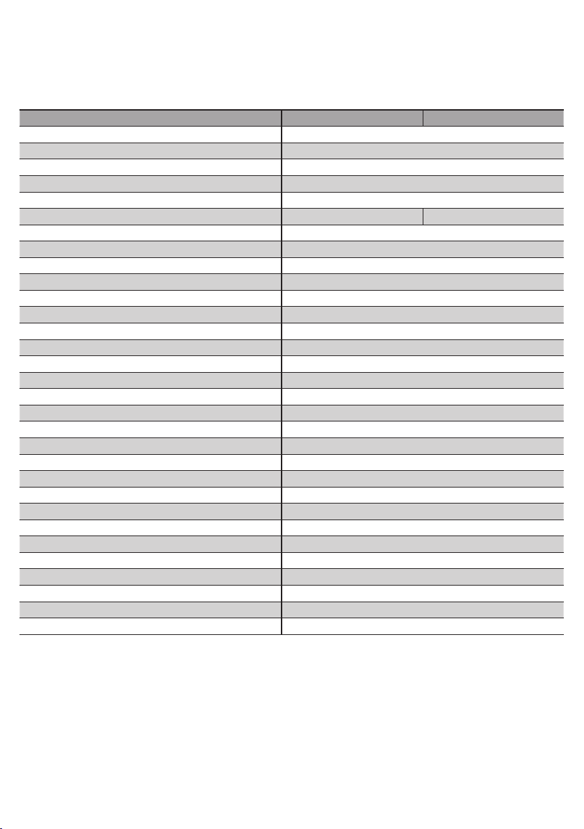
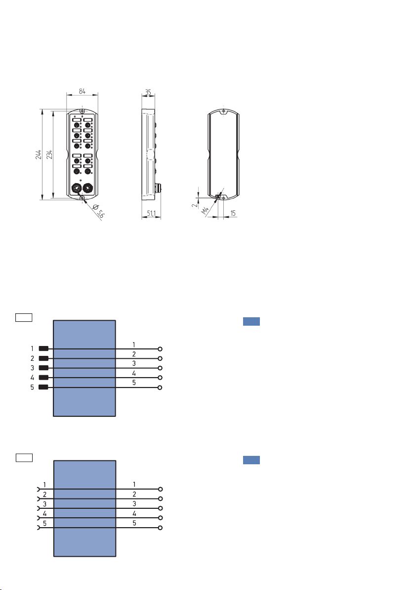
Wenglor ZAI02PN0 Series User manual

Operating instructions
Available as PDF only
Status: 12.09.2016
www.wenglor.com
ZAI02PN0x
Connection Boxes
EN

2
EN
Index
1. Use for Intended Purpose 3
2. Safety Precautions 3
3. Approvals and IP Protection 3
4. Technical Data 4
4.1. Connection table ZAI02PN0x 5
4.2. Housing Dimensions 6
4.3. Complementary Products 6
5. Application Notes 9
6. Mounting Instructions 9
7. Initial Operation 10
7.1. System Structure 10
7.2. Power Cable 11
7.3. Functional Earth 11
7.4. Industrial Ethernet Cable 12
7.5. Connecting Digital Sensors and Actuators 12
7.6. Diagnosis 13
7.6.1 LED Display PROFINET 14
7.7. Operation on a Controller 15
7.7.1 Overview of the modules for PROFINET 15
7.7.2 Detailed description of the modules for PROFINET devices 16
7.7.3 Diagnostic alarms 18
8. Web-based Configuration 20
8.1. Call up the Administration Interface 20
8.2. Overview Page 23
8.3. Device settings 24
8.4. Digital I/O Ports Settings 26
9. Maintenance Notes 27
10. Proper Disposal 27
11. EU Declaration of Conformity 27

3
1. Use for Intended Purpose
This wenglor product must be used in accordance with the following functional principle:
Connection Box
The connection box is used for reducing the cabling work involved when there are many Sensors/actuators
in a system and for connecting them to an industrial Ethernet network. The digital inputs and outputs can be
activated or evaluated via the network.
2. Safety Precautions
• This operating instruction is part of the product and must be kept during its entire service life.
• Read this operating instruction carefully before using the product.
• Installation, start-up and maintenance of this product has only to be carried out by trained personnel.
• Tampering with or modifying the product is not permissible.
• Protect the product against contamination during start-up.
• Not a safety component in accordance with the EU Machinery Directive.
3. Approvals and IP Protection
RoHS

4
EN
4. Technical Data
Order number ZAI02PN01 ZAI02PN02
Supply voltage 18...32 V DC
Power consumption of device max. * 0.1 A
Power consumption of system max. ** 1.8 A
Temperature range –25...60 °C
Voltage drop switching outputs < 2,5 V
Max. Switching current switching outputs 0.6 A 2 A
Max. total current of the I/O ports 9 A
Sensor Supply Voltage (Pin 1) 200 mA
Inputs according to DIN EN 61131-2:2003 Type 2
Digital I/O ports short-circuit protected yes
Digital I/O ports overload protected yes
Digital I/O ports reverse polarity protected yes
Number of standard I/O pins 16
Housing material Aluminum
Weight 1100 g
Protection class IP67
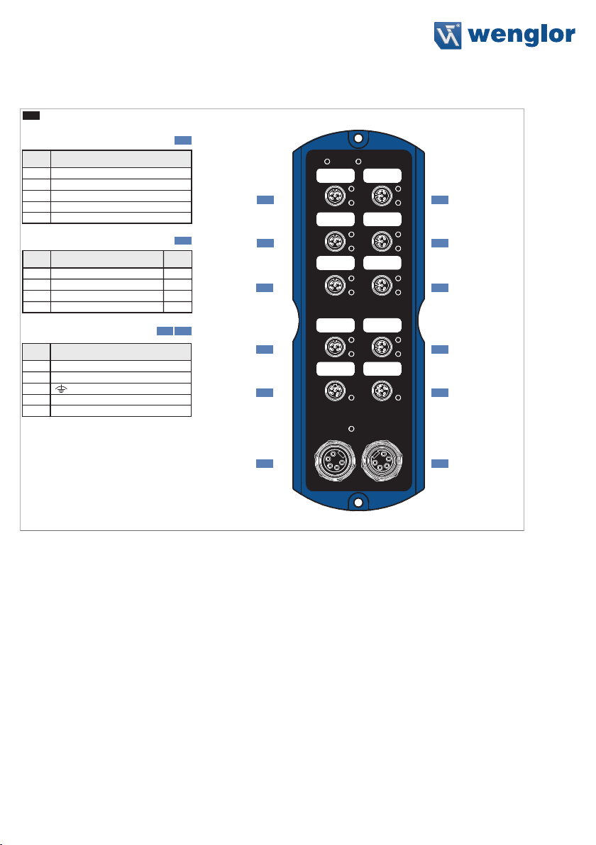
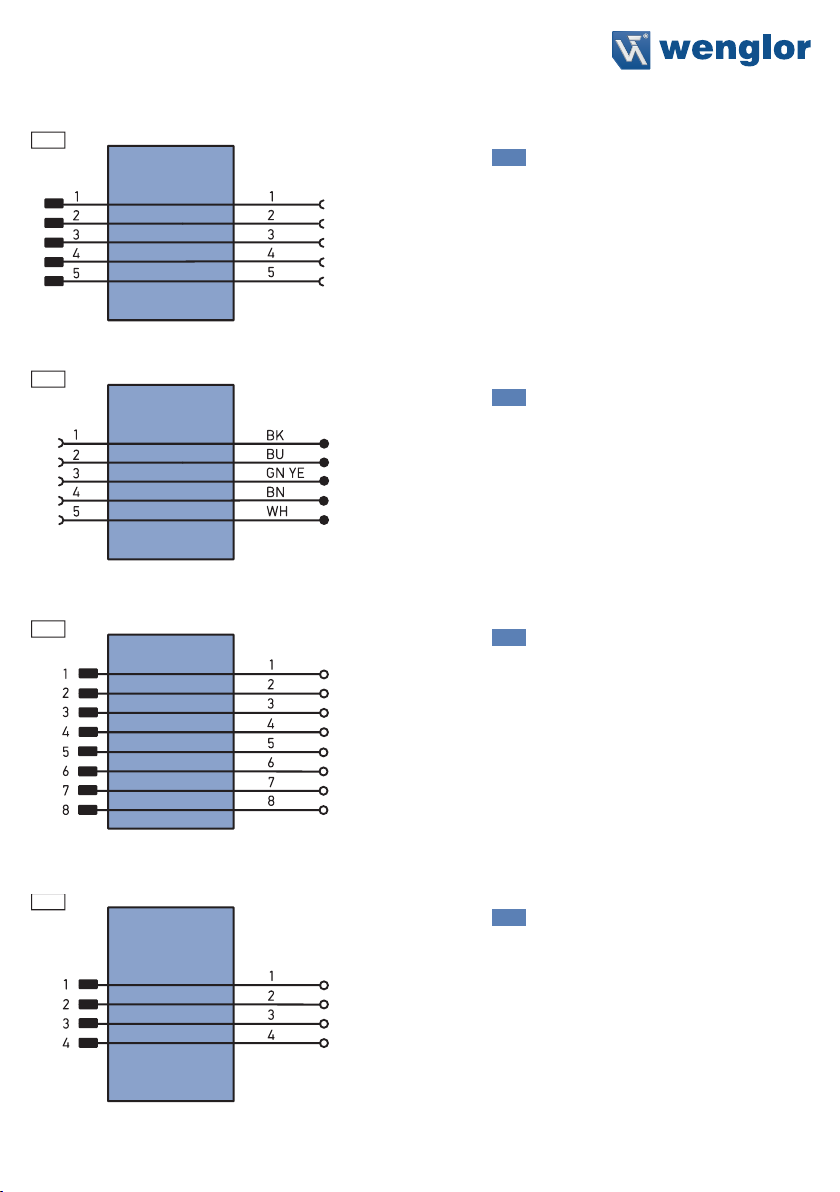
Type of connection power 7/8", 5-pin
Type of Connection Industrial Ethernet ports M12×1, 4-pin, D-coding
Type of Connection Digital I/O ports M12×1, 4-pin, A-coding
Number of Industrial Ethernet ports 2
Number of Digital I/O ports 8
Baud Rate 10 Mbit/s / 100 Mbit/s
Transmission Mode Full / Half Duplex
Webserver yes
Switch Mode Store & Forward
VLAN Prioritization ja
Default IP 192.168.100.1
Auto-Crossover yes
Auto-Negotiating yes
Auto-Polarity yes
Protection class III
* Maximum own power consumption of the product without additional loads
** Maximum own power consumption of the product with additional loads
Full assignment of all digital I/O ports with sensor supply (without outputs)

5
4.1. Connection table ZAI02PN0x
www.wenglor.com
2
FunctionPin
1 TxD (+)
2 RxD (+)
3
4
Socket 2
In/
Out
TxD (−)
RxD (−)
Out
In
Out
In
Function
Pin
1 +24 V DC
2 I/O
3
4
Socket 1
GND
I/O
Suitable Plug:
51
Suitable Plug:
Socket 3 7877
Suitable Plug:
5
Function
Pin
1 0 V DC
2 0 V DC
3
4+24 V DC USystem/Sensor
5 +24 V DC UDigital I/O
2
2
Socket 1
Socket 1
2
51
Socket 1
Socket 2
77
Socket 3
2
Socket 1
2
2
Socket 1
Socket 1
2
51
Socket 1
Socket 2
78
Socket 3
2
Socket 1
53

6
EN
4.2. Housing Dimensions
4.3. Complementary Products
wenglor offers Connection Technology providing field wiring means.
Connection plug, 7/8", 5-pin Order number: ZAT77NN01
Suitable Plug:
77
S82
Connection plug, 7/8", 5-pin Order number: ZAB78NN01
Suitable Plug:
78
S87

7
Connecting cable, 7/8", 5-pin Order number: ZAV78R201, Cable length: 2 m
Suitable Plug:
78
S76
Connecting line, 7/8", 5-pin Order number: ZAS78R601, Cable length: 10 m
Suitable Plug:
78
S75
Connector Plug RJ45; 8-pin Order number: ZAT45NN01
Suitable Plug:
45
S48
Connection plug, M12×1, 4-pin Order number: ZAT51NN01
Suitable Plug:
51
S08

8
EN
Connecting cable M12×1; 4-pin; D-coding Order number: ZAV51R201, Cable length: 2 m
Order number: ZAV51R601, Cable length: 10 m
Suitable Plug:
51
Order number: ZAV51R202, Cable length: 2 m
Order number. ZAV51R602, Cable length: 10 m
Suitable Plug:
51
2
Connection and power supply cables
M12×1; 4-pin, different lengths are available for connecting the Sensor/actuator.
Legend
Wire Colors according to
DIN IEC 757
Platinum measuring resistor
not connected
Test Input
Test Input inverted
Trigger Input
Analog Output
Ground for the Analog Output
Block Discharge
Valve Output
Valve Control Output +
Valve Control Output 0 V
Synchronization
Receiver-Line
Emitter-Line
Grounding
Switching Distance Reduction
Ethernet Receive Path
Ethernet Send Path
Interfaces-Bus A(+)/B(–)
Emitted Light disengageable
Magnet activation
Input confirmation
Contactor Monitoring
Encoder A/A (TTL)
Encoder B/B (TTL)
Black
Brown
Red
Orange
Yellow
Green
Blue
Violet
Grey
White
Pink
Green/Yellow
Supply Voltage +
Supply Voltage 0 V
Supply Voltage (AC Voltage)
Switching Output (NO)
Switching Output (NC)
Contamination/Error Output (NO)
Contamination/Error Output (NC)
Input (analog or digital)
Teach Input
Time Delay (activation)
Shielding
Interface Receive Path
Interface Send Path
Ready
Ground
Clock
Output/Input programmable
Power over Ethernet
Safety Input
Safety Output
Signal Output
Ethernet Gigabit bidirect. data line (A-D)
Encoder 0-pulse 0-0 (TTL)
Encoder A
Encoder B
Digital output MIN
Digital output MAX
Digital output OK
Synchronization In
Synchronization OUT
Brightness output
Maintenance
PT

9
5. Application Notes
The Ethernet ports are fitted with overvoltage discharge protection. Internal varistors limit voltage surges to
approx. 70 V. The connecting cables of the Digital I/O ports must not be longer than 30 m.
6. Mounting Instructions
When mounting and operating the connection box, the corresponding electrical and mechanical regulations,
standards and safety rules must be observed. The connection box must be protected against mechanical influ-
ences. The connection box must be fastened in such a way that the mounting position cannot change. The
product is designed for use in the industrial sector. The industrial environment is characterized in that consum-
ers are not connected directly to the public low-voltage mains network. Additional measures must be taken for
use in the residential sector, business and commercial sectors.
The table below defines the tightening torques of the plugs and fastening options for ensuring compliant and
faultless operation.
Connection type Tightening torque in (Nm)
M12 0.4
7/8" plug 1.5
FE ground strap 2.2±0.2
Connection box mounting 4.0±0.2

10
EN
7. Initial Operation
Project planning, installation, start-up, maintenance and testing of the devices may only be carried out by quali-
fied electrical technicians familiar with the safety standards of automation technology.
Only cables and accessories that meet the standards and requirements for safety, electromagnetic compat-
ibility and, if necessary, telecommunications terminal equipment and the specifications. In case of damage, the
product must not be used further on. In the event of improper use, the guarantee and liability claim against the
manufacturer shall lapse.
Information concerning which cables and accessories are approved for installation can be found at
www.wenglor.com or are described in this manual.
7.1. System Structure
Industrial Ethernet
Digital
I/O Ports
Digital
I/O Ports
Power

11
7.2. Power Cable
1
2
34
5
1
2
3
4
5
Power In Power Out
0 V Pin 1 0 V Pin 1
0 V Pin 2 0 V Pin 2
Pin 3 Pin 3
24 V max. 9 A Pin 4 USystem/Sensor 24 V max. 9 A Pin 4
24 V max. 9 A Pin 5 UDigital I/O 24 V max. 9 A Pin 5
The 7/8" plug is designed for a maximum current of 9 A per pin. This must be taken into account when looping
the supply voltage.
The connection box must be connected to a power supply of 18 to 32 V DC. The USystem/Sensor supplies the
connection with voltage and the UDigital I/O provides the power supply of the Digital I/O ports.
The voltage of USystem/Sensor must not be switched off during ongoing operation and hence must not be con-
ducted via emergency stop circuits, since otherwise the connection box will not be able to participate in the
communication.
Measures must be taken in all cases to ensure that the supply voltage, measured at the remotest partici-
pant, does not fall short of the system supply voltage of 18 V DC.
To be complied with in reactive operation:
If the power supply of the Digital I/O ports is merged with the voltage supply of the connection box, there
will then be the risk of a communication disruption in the event of a short-circuit on the I/O devices.
7.3. Functional Earth
The FE connection is on the lower front edge of the connection box. To ensure proper functioning in accor-
dance with the EMC regulations specified in the data sheet, we recommend using our ground strap, which is
included in the scope of delivery (for tightening torque see “Mounting Instructions” on page 9).

12
EN
7.4. Industrial Ethernet Cable
wenglor provides a variety of preassembled industrial Ethernet cables.
To ensure cabling as simple and reliable as possible, we recommend using our preassembled industrial Ether-
net cables. It is advisable to only use cables certified in accordance with PROFINET standard in order to ensure
safe and compliant operation (please also see PROFINET Cabling and Interconnection Technology – Guideline
for PROFINET).
Assignment of the Industrial Ethernet connection (D-coding):
1
2
3
4
Pin Function
1 TxD (+)
2 RxD (+)
3 TxD (–)
4 RxD (–)
7.5. Connecting Digital Sensors and Actuators
1 2
34
Pin Function
1 24 V
2Freely programmable
input/output
3 0 V
4Freely programmable
input/output
Sockets that are not used must be provided with caps, which are included in the scope of supply. Otherwise,
the protection class IP67 cannot be guaranteed.
A short-circuit on the IO-pins triggers an alarm in the controller. This message that can be enabled via the de-
vice parameters indicates whether a short-circuit to ground or UDigital I/O is present. In the event of a short-circuit
on the Digital I/O ports, the communication with the connection box via PROFINET remains unaffected. Even
the inputs can still be read, but a separate power supply of UDigital I/O and USystem/Sensor is required, however.
ZAI02PN01 and ZAI02PN02 Connection Boxes are equipped with a mechanism which protects the electronics
from overheating. Both of the Connection Boxes switch the digital outputs off in the case of overtemperature,
for example due to excessive current output or operation outside of the specified ambient temperature range.

13
After a cool-down phase, the Connection Boxes are started back up again automatically. The momentary status
can be read out via the PROFINET “Status” module.
Overall current monitoring for digital I/O voltage (UDigital I/O) has also been integrated into the ZAI02PN02. This
is necessary because current of up to 4 A can be made available at each port. However, the utilized power plug
has a rating of max. 9 A. This total may not be exceeded by the sum of all digital outputs. If the limit value is
nevertheless violated, the Connection Box is switched to an error status and all outputs are deactivated. The
Connection Box then has to be reset in order to start it back up again. Supply power must be briefly interrupted
to this end.
Looping through to the power out socket is not monitored in this case, and adherence to the specified maxi-
mum current values for the power in plug must be assured by the user.
7.6. Diagnosis
Assignment example:
CS
X0
X2 X3
X4 X5
X1
X6 X7
AB
MS
Power
IN
IO
0.4
IO
1.4
IO
0.5
IO
1.5
IO
0.6
IO
1.6
IO
0.7
IO
1.7
IO
0.2
IO
1.2
IO
0.3
IO
1.3
IO
0.0
IO
1.0
IO
0.1
IO
1.1
L/A L/A
OUT
Power Power
www.wenglor.com
ZAI02PN0x

14
EN
7.6.1 LED Display PROFINET
CS MS
The status display for the communication is marked on the connection box with CS and MS.
Designation Condition Function
CS (Communication
Status)
Off Connection (AR) with controller established
Green Protocol not initialized
Red No connection (AR) with controller established
MS (Module Status)
Off Module status OK
Red Device fault
Red flashing Detection function, may be activated via Engineering Tool
The LED display on the M12 sockets displays the diagnosis for the corresponding socket.
A
L/A
Designation Condition Function
L/A Green Link exists
Green flashing Communication via port
X1 IO
0.0
IO
1.0
Designation Condition Function
IO 0.0/IO 1.0 Yellow Input UB at Pin 2/4
Output Switching Output to UP Pin 2/4
Red Output Short-circuit at Pin 2/4

15
7.7. Operation on a Controller
If you wish to start up the device on a controller, please carry out the following steps:
• Attach the connection box to the supply voltage and connect this to the controller via one of the Ethernet
ports. You can find the appropriate connection technology on the wenglor homepage.
• Install the associated device-specific electronic description file (with Profinet the GSDML file) in the
Hardware Manager of the controller. You will find the required file ready for download at:
www.wenglor.com Product World Product Search (Enter the product number) Download
Product Description File.
• The following procedure can be applied by way of example (example based on the Step 7 Engineering
Tool of a Simatic-S7 controller from Siemens):
• Insert the device into the Profinet cable
• Afterwards, call up the object properties of the device
• Assign a name of your choice to the device
• Allocate an Ethernet address to the device
• Assign the product by means of device names/IP address (detection via Mac address)
• Transfer the configuration to the controller
A detailed description for different controllers and for the installation of the files or for the project planning of
the network can be found in the help files of the relevant controller. wenglor offers an example quick guide on
starting up a PROFINET device for the Simatic-S7 controller from Siemens and the appropriate software Step 7
Engineering Tool (Product World Product Search (Enter the product number) Download General
instructions).
7.7.1 Overview of the modules for PROFINET
Name Cyclical/input Parameter slot
16 bit digital input/output Digital input/output 1 (fixed)
The following describes the detailed design of the modules.

16
EN
7.7.2 Detailed description of the modules for PROFINET devices
DAP 3/5: ZAI02PN01 V1.0/ZAI02PN02 V1.0
Module ID: 0x00000301
Submodule: 0x00000000
Parameter:
Name Data type Byte
offset Bit offset Bit length Default
value
Value
range
Change-
able Index Length
Web server
Access BitArea 0 0 1 0: Enabled Yes 300 1 byte
DAP 3/5 uses module 2
Module 1: 16 bit digital in/out
Module ID: 0x00000002
Submodule: 0x00000002
Format cyclical input and output data:
Example: x1P4 Digital I/O Port 1, Pin 4
ZAI02PN0x Input
Bit 7 Bit 6 Bit 5 Bit 4 Bit 3 Bit 2 Bit 1 Bit 0
Byte 0 x7P2 x6P2 x5P2 x4P2 x3P2 x2P2 x1P2 x0P2
Byte 1 x7P4 x6P4 x5P4 x4P4 x3P4 x2P4 x1P4 x0P4
Byte 2 Statusbyte 0
Byte 3 Statusbyte 1
ZAI02PN0x Output
Bit 7 Bit 6 Bit 5 Bit 4 Bit 3 Bit 2 Bit 1 Bit 0
Byte 0 x7P2 x6P2 x5P2 x4P2 x3P2 x2P2 x1P2 x0P2
Byte 1 x7P4 x6P4 x5P4 x4P4 x3P4 x2P4 x1P4 x0P4
Device Status
Process Data Input
Statusbyte Bit position Significance
0
0 Error (active as soon as another error bit is activated)
1 Internal device fault
2 Udigital I/O too low
3 Outputs switched off (due to excessive temperature)
4 Short-circuit on at least one output
5–
6 Temperature too high
7 Temperature too low
10 – 7 –

17
Parameter:
IO-Direction Pin2
Name Data type Byte
offset Bit offset Bit length Default value
IO Port 0 BitArea 0 0 1 0: Input
IO Port 1 BitArea 0 1 1 0: Input
IO Port 2 BitArea 0 2 1 0: Input
IO Port 3 BitArea 0 3 1 0: Input
IO Port 4 BitArea 0 4 1 0: Input
IO Port 5 BitArea 0 5 1 0: Input
IO Port 6 BitArea 0 6 1 0: Input
IO Port 7 BitArea 0 7 1 0: Input
IO-Direction Pin4
Name Data type Byte
offset Bit offset Bit length Default value
IO Port 0 BitArea 0 0 1 0: Input
IO Port 1 BitArea 0 1 1 0: Input
IO Port 2 BitArea 0 2 1 0: Input
IO Port 3 BitArea 0 3 1 0: Input
IO Port 4 BitArea 0 4 1 0: Input
IO Port 5 BitArea 0 5 1 0: Input
IO Port 6 BitArea 0 6 1 0: Input
IO Port 7 BitArea 0 7 1 0: Input
IO-Parameter
Name Data type Byte
offset Bit offset Bit length Default value
Short circuit diagnosis Bit 0 0 1 0: deactivated

18
EN
7.7.3 Diagnostic alarms
The appropriate alarm module should be set up in the controller in the case of an alarm message originating
from the connection box by short circuit at the ports (hardware interrupt OBs OB40-OB47). If this is not the
case, the CPU goes into the STOP mode in the case of an interrupt triggering event. The following alarm mes-
sages are output from the connection box to the controller:
Diagnostic I/O: Short-circuit after VCC (coming)
Api 0x00000000
Slot 0x0001
Subslot 0x0001
Channel 0: Port 0 (Pin2 or Pin4)
1: Port 1 (Pin2 or Pin4)
2: Port 2 (Pin2 or Pin4)
3: Port 3 (Pin2 or Pin4)
4: Port 4 (Pin2 or Pin4)
5: Port 5 (Pin2 or Pin4)
6: Port 6 (Pin2 or Pin4)
7: Port 7 (Pin2 or Pin4)
AlarmSpecifier 0x01, Diagnosis appears
ChannelErrorType 0x0100 (manufacturer-specific)
Diagnostic I/O: Short-circuit after VCC (going)
Api 0x00000000
Slot 0x0001
Subslot 0x0001
Channel 0: Port 0 (Pin2 or Pin4)
1: Port 1 (Pin2 or Pin4)
2: Port 2 (Pin2 or Pin4)
3: Port 3 (Pin2 or Pin4)
4: Port 4 (Pin2 or Pin4)
5: Port 5 (Pin2 or Pin4)
6: Port 6 (Pin2 or Pin4)
7: Port 7 (Pin2 or Pin4)
AlarmSpecifier 0x02, Diagnosis disappears
ChannelErrorType 0x0100 (manufacturer-specific)

19
Diagnostic I/O: Short-circuit after Gnd (coming)
Api 0x00000000
Slot 0x0001
Subslot 0x0001
Channel 0: Port 0 (Pin2 or Pin4)
1: Port 1 (Pin2 or Pin4)
2: Port 2 (Pin2 or Pin4)
3: Port 3 (Pin2 or Pin4)
4: Port 4 (Pin2 or Pin4)
5: Port 5 (Pin2 or Pin4)
6: Port 6 (Pin2 or Pin4)
7: Port 7 (Pin2 or Pin4)
AlarmSpecifier 0x01, Diagnosis appears
ChannelErrorType 0x0101 (manufacturer-specific)
Diagnostic I/O: Short-circuit after Gnd (going)
Api 0x00000000
Slot 0x0001
Subslot 0x0001
Channel 0: Port 0 (Pin2 or Pin4)
1: Port 1 (Pin2 or Pin4)
2: Port 2 (Pin2 or Pin4)
3: Port 3 (Pin2 or Pin4)
4: Port 4 (Pin2 or Pin4)
5: Port 5 (Pin2 or Pin4)
6: Port 6 (Pin2 or Pin4)
7: Port 7 (Pin2 or Pin4)
AlarmSpecifier 0x02, Diagnosis disappears
ChannelErrorType 0x0101 (manufacturer-specific)

20
EN
8. Web-based Configuration
The connection box is equipped with a web-based setting interface, which works independently of the oper-
ating system. You can easily set parameters for the connection box using a standard web browser. The net-
work settings are preset to the IP address 192.168.100.1, subnet mask 255.255.255.0 and standard gateway
192.168.100.254. The preset values are always assumed in the instructions.
Attention:
When using on a controller, settings changed through the website are overwritten by the controller.
8.1. Call up the Administration Interface
Start the web browser. Enter the IP address of the connection box into the address line of your browser and
press the ENTER key. The IP address of the connection box is preset to 192.168.100.1. To ensure that the
browser displays the current website settings, the website in question must always be refreshed automatically
in case of change. This setting must be changed browser-specific and is demonstrated here by means of Inter-
net Explorer as an example. Under Tools Internet options Browsing history Settings the selection
should be set to Every time I visit the webpage. Otherwise, any changes to the homepage might be displayed
incorrectly.
This manual suits for next models
2
Table of contents
Other Wenglor Cables And Connectors manuals
Popular Cables And Connectors manuals by other brands

RKC INSTRUMENT
RKC INSTRUMENT SRZP-01 instruction manual

Philips
Philips SWV4158W/10 datasheet

Matchmaster
Matchmaster 34MM-2K50 instruction manual

Philips
Philips SHH1212 Specifications

Keysight Technologies
Keysight Technologies Y1218A Installation note

Install Bay
Install Bay IB-HDAOC-015 instruction manual