SRS Lighting DXD-8NI User manual

( 1 / 24)
Instruction Manual
Models:
version 1.06.8 since 4 August 2017
ATTENTION
This instruction manual contains important information about the installation and the use of
the equipment. Please read and follow these instructions carefully.
Always ensure that the power to the equipment is disconnected before openin the
equipment or commencin any maintenance work.
DXD-8NI_en_manual_M238
1U 19” DMX RDM Merger
DXD-8NI
DDL4

( 2 / 24)
DXD-8NI is a two-input DMX mer er with HTP / LTP / DMX-A backup or DMX-B backup modes. It
support full RDM specification and It is ideal for applications where mer in of two DMX
si nals is needed. Examples of usa e are two DMX consoles controllin one dimmer system or
controllin of house li ht. Moreover, the unit can be used as a scene call device for callin of
the minimum DMX value. This value is then sent to dimmer with connected LED li hts in case
the main console is disconnected or LED li hts are flickerin on low DMX value because of
technical requirements of LEDs. DXD-8NI is equipped with a RJ45 update thru SRS Update
cable for later software updates accordin to customer’s needs. As addition to the DXD-8NI its
also equipped with screw terminal for remote call of presets via buttons connected as
keyboard.
Features:
• 3 x DMX512 optically isolated / boosted
• DMX RDM support
• Wide range of po er supply (AC100-240V)
• Various modes:
HTP – Higher takes presence
LTP – Last takes presence
DMX-A backup by DMX-B
DMX-B backup by DMX-A
Shift of DMX start address on each input and also output
ALW.ON minimum setting on the DMX via the SCENE call
DMX PRS – call of DMX scenes via DMX
External control via buttons
• Easy to setup and control using the Encoder + 2 buttons
• 12x2 LCD display
• Free firm are upgrade via SRS Firm are upgrade tool
DMX input/output
USITT DMX 512, DMX 512A, RDM support
Po er supply:
DC 12-36V, 160mA via external PSU
Dimensions & housing:
1U, 19” format, 482.5 x 44.5 x 145 mm, 2.23 k
Package consists of:
• DXD-8NI device
• AC110-230V with multiple country plu s to DC15V power adapter
• Printed manual

( 3 / 24)
IMPORTANT INSTRUCTIONS:
All safety and operatin instructions should be read before the equipment is installed or
operated.
IMPORTANT SAFETY INFORMATION:
The followin eneral safety precautions have to be observed durin all phases of
operation, service, and the repair of this equipment. Failure to comply with these
precautions or with specific warnin s in this manual violates safety standards of desi n,
manufacture, and the intended use of this equipment.
Do not operate this equipment in the presence of flammable ases or fumes. Operation of
any electrical instrument in such an environment constitutes a definite safety hazard. Do
not operate this equipment near water or in areas with wet floors or in hi h humidity
atmosphere where condensation forms on the equipment.
It should never be placed near or over a heat re ister or other source of heated air and it
should not be installed or operated without proper ventilation.
Device must be connected to the secured circuit with circuit breaker or main switch of
maximum 16A. The device does not contain any fuses and there are no serviceable parts
inside.
Warranty:
The product desi n should be varied to keep the product continuously updated. The
product price should be subject to possible variations for eventual rises of production
costs or duties. Claims for possible dama es durin the frei ht must be notified to the
carrier. All claims must be notified to the distributor or manufacturer within 8 days from
the receipt of oods. Buyer is responsible for the ri ht installation and the use of the
apparatus.
The apparatus is covered by a TWO-YEAR warranty from the date of purchase a ainst
defects of manufacture and components. Defects and breaka es caused by wron
use/connection are not subject to warranty. For any dispute is competent the Tribunal of
Bratislava, Slovak Republic.

( 4 / 24)
Device front panel:
On the front panel, there is set of DMX output connectors and an Encoder with two buttons and an
LCD display with 12x2 characters for orientation in the menu.
Device rear panel:
Rear panel features two roups of connectors marked as DMX INPUT A and DMX INPUT B that are
mer ed. There is a DC power supply connector on the ri ht. There is also screw terminal for
connection of external switches or keyboard in matrix mode
All connectors are wired accordin to the wirin codes below.

( 5 / 24)
Connectors:
DC connector
Pin 1 DC12-36V
Pin 4 DC GND
DMX IN / DMX OUT connector
Pin 1 Data CMN
Pin 2 Data -
Pin 3 Data +
Pin 4, 5 Not connected
RJ45 IN / RJ45 OUT connector
Pin 1, 3 Data +
Pin 2, 6 Data -
Pin 4, 5 NC
Pin 7, 8 DATA CMN
Preset buttons + OC outputs connector

( 6 / 24)
Selected merger
mode:
HTP A-B
LTP A-B
BKP B>A
BKP A>B
DMX PRS
DMX SFX
This screen
appears in LATCH
mode.
Information about
active buttons
BTN:
0: not active
1: active
Positions:
Bottom ri ht
representin button
#1, from the ri ht to
the left bottom and
then top line
incrementin by 1
Bottom row
shows the active
scene number.
No scenes are
active. DMX oes
directly from
input to output.
These screens appear in FLASH
mode.
Information about active buttons
on the input BTN:
0: not active
1: active
Device use:
Device is controlled by an Encoder (rotation and press)
and 2 buttons: ESC and ENTER .
See the symbol description for orientation in the menu:
After the device is plu ed in, home screen with the product type
and SW version appears. The home screen is automatically
replaced by the stand-by screen displayed below. The stand-by screen consists of several
pa es that can be seen by the rotation of Encoder.
NAVIGATION IN THE MENU:
Press the Encoder to enter the menu.
In the menu, there are several options to choose from:
1. Merger mode
2. Display
3. DMX settings
4. OC output
5. Buttons
6. Factory reset
Press “ENTER” to enter the submenu.
Press “ESC” to escape from the submenu or to return to previous level of the menu.
Use buttons and the Encoder to proceed with the required function accordin to the
schematics below.
Objects in yellow color indicate blinkin and the position of the cursor.
To confirm each settin , scroll down to “OK” and press “ENTER”
Channels A/B:
NC: Not connected
OK: Correct DMX
si nal
ERR: Error on the
DMX
RDM: RDM
communication in
pro ress
Output options:
Stopped / DATA /
unknown / Scene /
Preset / RDM /
to 0% / to 100% /
A HTP B / 0
Not present in the
DMX PRS mode

( 7 / 24)
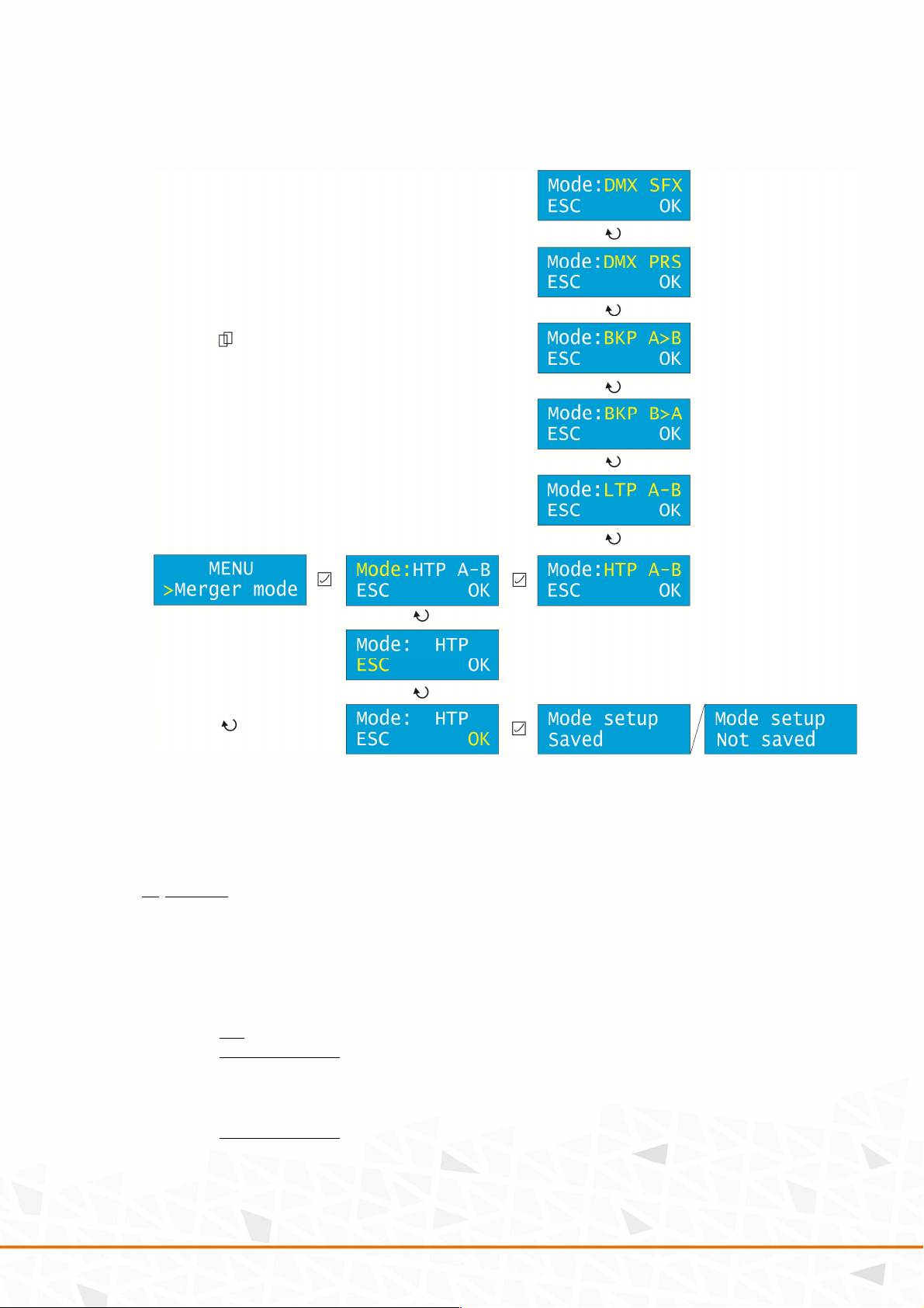
1. Merger mode
This submenu allows you to set the desired mer er mode.
There are several modes of mer in . One of the followin modes can be chosen:
• HTP A-B Hi her takes presence.
• LTP A-B Last takes presence.
• BKP B>A Backup by DMX B in case of si nal loss on DMX A.
• BKP A>B Backup by DMX A in case of si nal loss on DMX B.
• DMX PRS DMX preset function /More info below/.
• DMX SFX DMX safety function /More info in the SFX setup/.
For all merger modes except of the Preset /PRS/ one, the follo ing diagram is valid:
DMX PRS /DMX preset/ is a function that allows its user to save and call scenes directly from
a console usin channels 1 to 16. The console is connected to the DXD device usin the DMX
INPUT B. Faders on channels 1 to 16 respectively, serve as controllers of the preset output
intensity. Activatin channel 17, the DXD unit i nores the DMX A input. Channel 18 is used to
save the individual presets.
The DMX preset can also be controlled usin an additional equipment of the DXD device. In
this case, the presets are called usin a sin le press of a correspondin button. They are
saved when the button is held for more than 5 seconds.
The followin screen with the correspondin Preset number appears after the preset is saved:
and the device shows their values in the home screen.
The follo ing diagram is valid for the PRS Preset mode:
( 8 / 24)
Press “ENTER” to enter the Merger mode. Press “ENTER” a ain to adjust the mer er mode.
Scroll the Encoder to reach the desired option and confirm by “ENTER”. Scroll down to “OK”
and press “ENTER” to save the settin s.
2. Display
This submenu allows you to set the Sleep function and the intensity of the Backlight.
Press “ENTER” to enter the Display. Scroll the Encoder to choose between the Sleep and
Backlight settin and confirm by “ENTER”.
Sleep: Sets the time of inactivity (in seconds) after the device oes into sleep mode (display is
off).
Off: Sleep mode disabled
Adjustable ran e: 5s-100s
Press any key to wake up.
Backlight: Sets the intensity of display li ht.
Adjustable ran e: 0-100%
Scroll the Encoder to choose the desired value and confirm by “ENTER”. Scroll down to “OK”
and press “ENTER” to save the settin s.

( 9 / 24)
3. DMX settings
This submenu allows you to set several values of the DMX.
Press “ENTER” to enter the DMX sett.
In this submenu, there are several options to choose from:
a. Loss of DMX
b. Manual call
c. SFX setup
d. PRS Lock
e. Start address
f. Scene 1
g. Scene 2
…
h. Scene 8
Use the Encoder to navi ate in the submenu. Press “ENTER” to enter the submenu.
( 10 / 24)
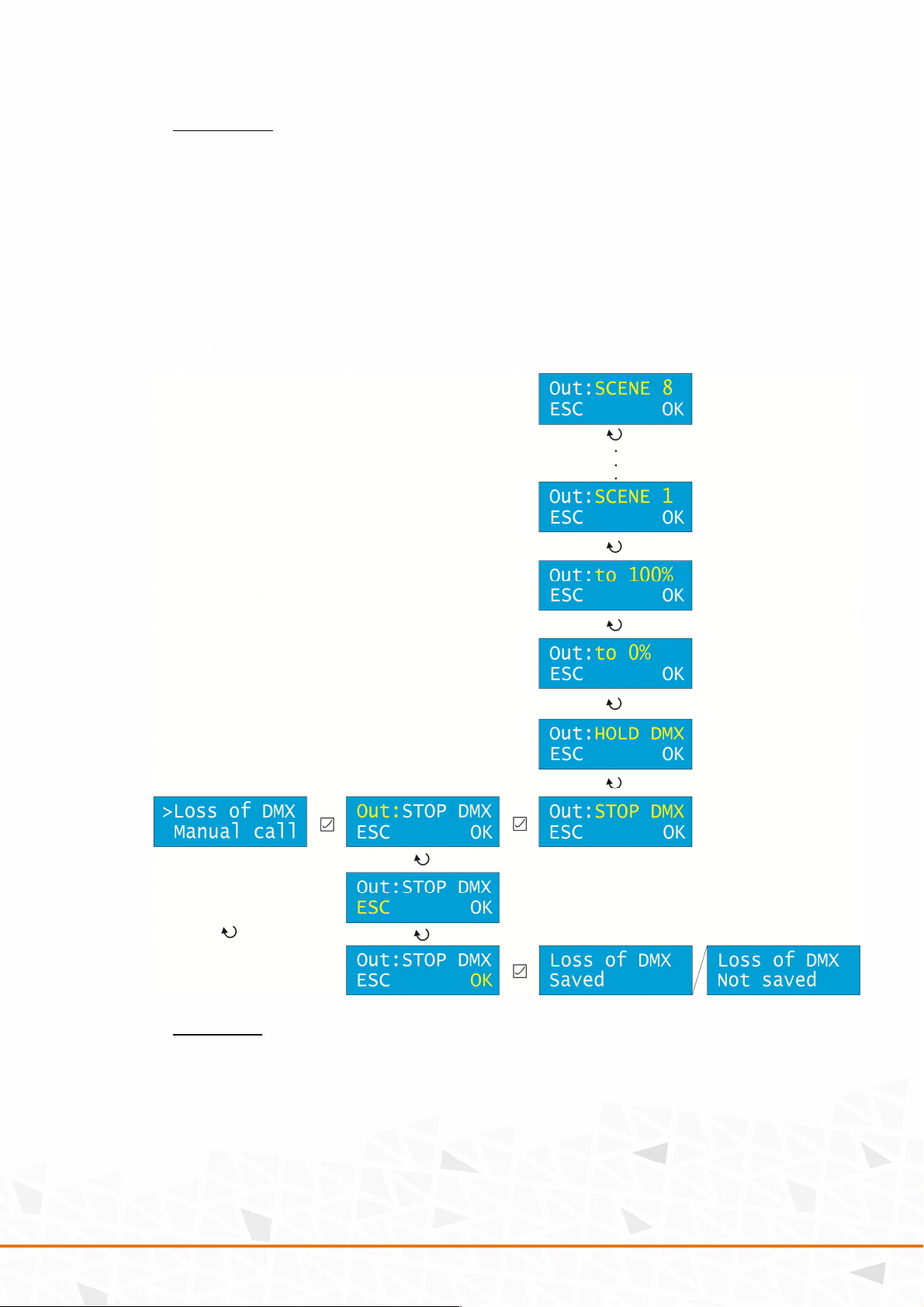
a. Loss of DMX
This submenu allows you to set an action that is executed in case the DMX si nal is lost.
There are several options to choose from:
• STOP There is no DMX transmission on the output.
• HOLD Transmits last DMX data.
• to 0% Transmits DMX with values 0.
• to 100% Transmits DMX with values 255.
• SCENE 1-8 Calls the preset scene that is bein transmitted.
Press “ENTER” to enter the Loss of DMX submenu. Press “ENTER” a ain to adjust the option.
Scroll the Encoder to reach the desired option and confirm by “ENTER”. Scroll down to “OK”
and press “ENTER” to save the settin s.
b. Manual call
This submenu allows you to set a scene that is executed when a button is pressed.
If there is
NO DATA on both DMX lines, up to 3 scenes can be called usin a manual switch connected to
either DMX input dependin on the time of the button bein pressed:
Short press: Simply press the button in time less than 0.3s
Middle press: Press and hold the button for more than 0.3s, but less then 0.7s
Long press: Hold button for more than 0.7s

( 11 / 24)
In the Man al call submenu, rotate the Encoder to select the desired len th of a press and
confirm by “ENTER.” Rotate the Encoder to select the desired scene value (or OFF to disable
this function) and confirm by “ENTER.” Scroll down to “OK” and press “ENTER” to save the
settin s.
c. SFX setup
This submenu allows you to set safety limits to the desired channel.
For one channel (1-512),
you can set the top and bottom values (ran e 1-255).
In the SFX set p submenu, rotate the Encoder to navi ate between the Channel, top and
bottom val e and confirm by “ENTER.” Rotate the Encoder to select the desired value and
confirm by “ENTER.” Scroll down to “OK” and press “ENTER” to save the settin s.
( 12 / 24)
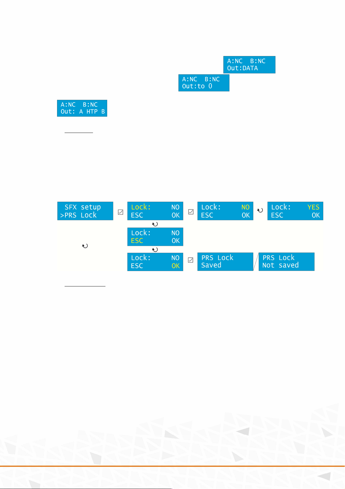
If the mer er falls into tolerable ran e, the home screen shows: . If it is
outside of the ran e, the home screen shows: . If both channels are
functionin , there is a si nal on both of them and the precedence is accordin to the HTP:
.
d. PRS Lock
This submenu allows you to enable or disable the Preset Lock. The Preset Lock serves as a
safety feature preventin from undesired button press on the preset equipment. When active,
the SAVE function of the preset is disabled.
In the PRS Lock submenu, press “ENTER” to enter into the options. Rotate the Encoder to alter
between YES and NO and confirm by “ENTER.” Scroll down to “OK” and press “ENTER” to save
the settin s.
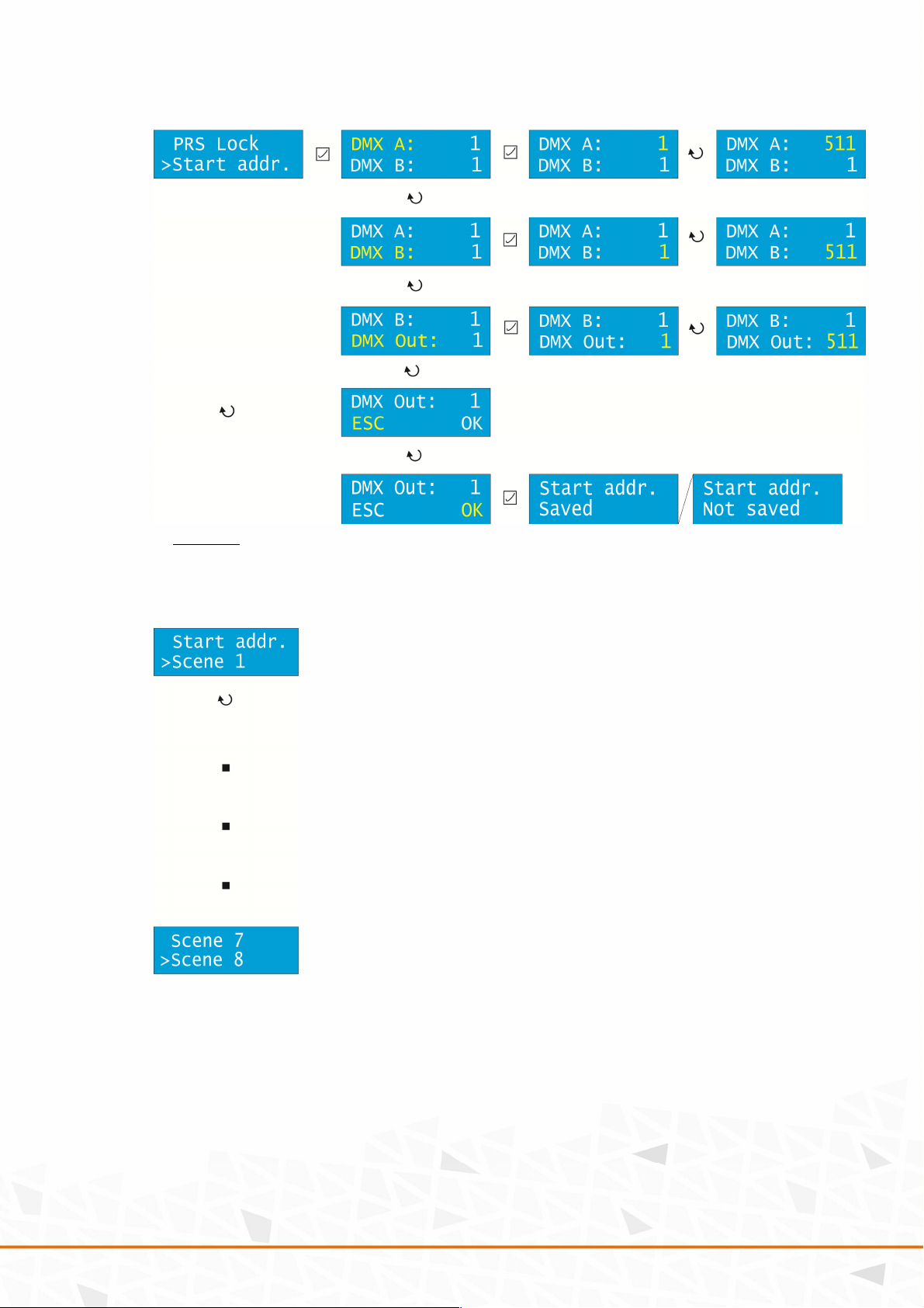
e. Start address
This submenu allows you to set the Start address of the DMX A and B Inputs and the Output.
The address can be set in a ran e of 1 - 511.
In the Start addr. submenu, rotate the Encoder to select the desired input or output and press
“ENTER” to confirm. Rotate the Encoder to choose the desired value and confirm by “ENTER.”
Scroll down to “OK” and press “ENTER” to save the settin s.
( 13 / 24)
f. Scene #
The last options of the DMX settings submenu are the settin s of scenes 1-8. Scroll the
Encoder to select the desired scene number to be adjusted and confirm by “ENTER.”
The Scene submenu allows you to set up each scene and to load them into the DMX A & B
inputs, respectively. There are the followin options to choose from:
• Setup
• Load DMXA
• Load DMXB

( 14 / 24)
In Setup submenu:
- every scene can be assi ned one channel that loads it /scene is loaded
proportionally/
- if more scenes are active, HTP and HTP DMX-A are made of them
- there is 1024 reserved bits for scene settin to the EEPROM
- memory is mana ed dynamically
Press “ENTER” to set up the scene. Scroll down to select one of the followin options:
• Mode
• Control channel
• Control button
• Start channel
• Size
Mode
This option selects the mode of the scene. It can be OFF, ON, or ALWAYS ON.
OFF: Scene is turned off
ON: Scene is turned on
ALWAYS ON: Scene is always on and preheat is performed as follows:
Loaded value is a minimum value on the output and the rest (remainin to 255) is
linearly divided. Ran e of DMX values is 0-255. Therefore, the hi hest load value is
255. This yields to a simple formula:
255 – channel load value = value of the preheat
Example: The channel load value is 100. 255 – 100 = 155.
155 is the value of the preheat.
Scroll the Encoder to the desired option and confirm by “ENTER.”
Control channel
This option allows you to select the control channel that calls the scene in a ran e of 1-512.
Scroll the Encoder to the desired option and confirm by “ENTER.”
Control button
This option allows you to select the control button that calls the scene in a ran e of 1-15.
Scroll the Encoder to the desired option and confirm by “ENTER.”
D e to the capability of the hardware, only b ttons in a range of 1-7 can be sed with this
feat re.
Start channel
This option allows you to select the start channel where the scene be ins in a ran e of 1-512.
Scroll the Encoder to the desired option and confirm by “ENTER.”
Size (in B):
This option allows you to set the number of channels that are assi ned for a scene. Maximum
memory is 1024B for all scenes in total. Use it wisely. Scene is saved to EEPROM.
Scroll the Encoder to the desired option and confirm by “ENTER.”

( 15 / 24)
Scroll down to “OK” and press “ENTER” to save the settin s.
Each scene can be saved by a lon press of a button (for more than 10 seconds.)
Load DMXA/DMX submenu is used to decide whether to load the scene from the DMX-A or
the DMX-B to the memory. The scene is loaded ri ht after the entry to this submenu.
Accordin to the chosen Merger mode, the resultin output value is enerated and used for
scene calculation on the output.

( 16 / 24)
Scroll down to Load DMXA or DMXB respectively and press “ENTER” to load the correspondin
scene from the DMX A or B input. Scroll the Encoder to accept (YES) or deny (NO) the settin
and confirm by “ENTER.”
Press “ESC” to return to the main menu.
4. OC /Open Collector/ output /useful only in DXD-8NI version/
The DXD unit features 4 open collectors that serve as an additional switchin equipment. For
each of them, the DMX output address and the switch value can be selected.
Press “ENTER” to enter the OC o tp t submenu. Scroll the Encoder to select one of Address
and switchin value. The number behind represents the correspondin open collector (1-4).
Press “ENTER” to confirm and scroll the Encoder to select the desired value and confirm by
“ENTER.” Scroll down to “OK” and press “ENTER” to save the settin s.

( 17 / 24)
5. Buttons
DXD-8NI device features the network interface that serves as a platform for additional buttons.
BT on the NI.
This submenu allows you to set the buttons.
Press “ENTER” to enter the Logic. Scroll the Encoder to choose between NO (Normally Open)
and NC (Normally Closed) and confirm by “ENTER”.
Scroll down to F nction to choose between FLASH and LATCH.
FLASH allows you to activate one button at a time. By activatin another button, the
previous button is deactivated. To deactivate all buttons, activate the Transparent scene
button.
LATCH allows you to activate as many buttons as you wish by pressin them. Press each
button a ain to deactivate it and so on.
Confirm by “ENTER”.
Scroll down to the Mix mode to choose between LTP and HTP mode in case both button and
fader are active. Confirm by “ENTER”.
Scroll down to the Transparent scene to choose value between 0 and 15. This is the button
number that is used to deactivate all scenes. Confirm by “ENTER”.
Scroll down to “OK” and press “ENTER” to save the settin s.
6. Factory reset
This submenu allows you to reset the unit to the factory defaults.
THIS OPTION WILL DELETE ALL YOUR SETTINGS AND SAVED SCENES!!!
Scroll the Encoder to YES and confirm by “ENTER”.

( 18 / 24)
MENU structure:
*

( 19 / 24)

( 20 / 24)
USB SW update:
For Windows XP/7/8, the followin drivers from FTDI are required:
http://www.ftdichip.com/Drivers/D2XX.htm
Installation manual can be found here:
http://www.ftdichip.com/Support/Documents/InstallGuides.htm
Flashin window:
1. Connect the SW-UPG-x USB to RS485 cable to
the computer and the DMX-A port of DXD-8NI.
2. Run the boot loader.
3. Click on the Open file button and select the file
with firmware you wish to flash.
4. Select Address to 1 and tick Fast Pro ram.
5. Click Pro ram and you will see the pro ress of
flashin .
6. After the flash, one of two messa es appears on
the display of DXD-8NI:
a. BOOTLOADER DONE – flashin went correctly
b. BOOTLOADER ERROR – wron firmware: press ESC and SET at the same time and
try a ain.
For help, check firmware or contact manufacturer at sales@srs- roup.com.
Table of contents
Other SRS Lighting Dj Equipment manuals


